
So you think you know about microphones? After reading this article by Vivian Capel you will!
Along with the loudspeaker, the microphone is the most often used transducer in the world. In broadcasting, recording, noise measurement and communications; they come in all sorts and sizes. Millions are in use at any given moment. Yet unlike the loudspeaker, they are little understood except by the professional user. As with any other component, appreciation of the working principles and operation helps considerably in the choice of a suitable unit for a particular purpose and its subsequent utilization. This article will explore these factors with a view to making the most suitable choice.
Transducer Types
There is more than one way of converting sound into electrical energy, and most of the practical ones have been used in various microphone designs. Some of these are as follows:
Carbon: Carbon granules are packed between two plates, often also made of carbon, one of which is fixed and the other moveable. The moving one is linked to a diaphragm so that sound pressure waves acting on it alternately compress and release the granules. This produces a variation of resistance across the plates through the granules. A current is passed through from an external DC source, which varies according to the resistance fluctuations.
An output voltage can be obtained by a resistance/capacity coupling circuit or by means of a transformer. The transformer primary, DC source and microphone are connected in series, so that an AC output signal appears across the secondary.
The advantage of the carbon microphone is high output (it can drive an earpiece direct with no amplification) and it is also extremely robust. Disadvantages are poor frequency response due to the inertia of the moving system, non-linearity (and hence distortion) and noise produced by the granules rubbing over each other. Uses are therefore confined at present to telephone and other communications.
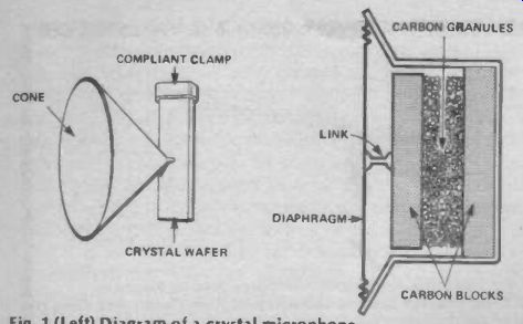
Fig. 1 (Left) Diagram of a crystal microphone.
Fig. 2 (Right) Diagram of a carbon microphone.
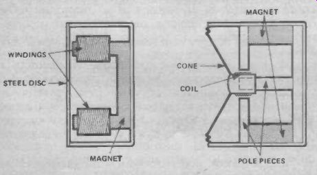
Fig. 3 (Left) Diagram of a moving-iron, or magnetic, microphone.
Fig. 4 (Right) Diagram of a moving-coil microphone.
Crystal: Various natural and man-made substances such as rochelle salt (sodium potassium tartrate), quartz, tourmaline, barium titanate and lead zirconate titanate, exhibit the piezoelectric effect--they generate a voltage when subject to stress or strain. The basic crystal microphone consists of a thin wafer of crystal secured at one side but free at the other. A cone is mounted with its apex bearing against the wafer near its free side and the sound pressure variations cause sympathetic flexing of the crystal and the production of a corresponding voltage.
Variations of this are the bi-morph, which has two wafers cemented together to give a push-pull effect, whereby one is stretched while the other compressed; this gives twice the out put and partial cancellation of non-linearities. There is also the multimorph, or sound-cell, which has several crystal elements and dispenses with the cone; the sound activating the crystals directly. Output is lower, but cone resonance is eliminated.
The advantage of the crystal unit is that of a high output voltage without an external DC source; it is also relatively inexpensive. Disadvantages are its fragility; the wafers crack easily with physical shock and they are affected by humidity. Man made crystals are rather better than the natural ones in these respects. Frequency response top end due to inertia effects. The main disadvantage is the very high impedance (around 1 M-O) which results in severe loss of high frequencies over comparatively short screened cables due to capacitance effects.
When used (with short leads) to drive valve input circuits in cheap PA amplifiers and tape recorders, the high output and high impedance eliminate the need for an input transformer. They are also used to measure vibration in some industrial applications.
Moving-Iron: A steel disc is supported over the pole-pieces of a permanent magnet on which are wound a pair of coils. It vibrates as a result of the sound pressure wave and so the spacing between the disc and the pole-pieces varies. The magnetic field also varies therefore and the flux lines cut the windings, inducing an EMF. Variations include balanced and rocking armature types.
Advantages are robustness and that units can be made very small if required. They can also be used for machinery vibration tests which would destroy other types of transducer. Disadvantages are poor frequency response, pronounced resonance of the disc and distortion caused by unequal flux variation. They are rarely used other than for vibration or sub-miniature applications.
Moving-coil: One of the most common types of transducer, the moving-coil microphone works in exactly the same way as a loudspeaker, only in reverse. The coil at the apex of the cone or diaphragm is immersed in a magnetic field between the concentric poles of a permanent magnet. Movement of the cone and coil induces current into the windings which is proportional to the sound pressure acting on the cone.
The advantages are high quality signals with extended frequency response and the ability to withstand hard usage. It is not easily overloaded by very loud sounds. The disadvantage is the comparatively high mass of the cone/coil assembly which puts a resonance peak in the frequency response between 2-5 kHz. This is a particular drawback for public address work where any resonance in the microphone response will initiate early acoustic feedback. With some microphones the peak can be 5-6 dB or even more, but the better models have it damped to around 2-3 dB. Double-transducer models are available, although these are expensive. They work like a speaker with a woofer and tweeter, one handling the low and the other the high frequencies. An electronic crossover ensures that only those frequencies within the designed range of each unit are supplied to the output. The resonant peaks of each are pushed outside of the pass range, so a flat response free from peaks is achieved.
With some applications the moving-coil resonance peak is considered an advantage, and gives what is sometimes termed a 'presence effect'. As the peak coincides with that part of the frequency spectrum at which most ambient noise occurs, it gives such ambience emphasis. So, background sounds are brought into on-the-spot recordings, interviews and the like to add realism. It can also brighten some instruments such as the piano and render certain vocalists with poor articulation a mite more intelligible. It will also emphasize a lisp, and give strings a wiry tone.
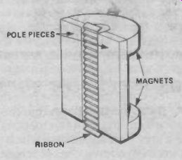
Fig. 5 Diagram of a ribbon microphone.
Ribbon: A corrugated ribbon is suspended edgeways between the pole pieces of a magnet so that as the air molecules impinge upon it, it moves back and forth and generates a current. In effect it is a single-turn moving coil without a cone. The impedance is very low, around 0.1 ohms and so a built-in matching transformer is required. The area affected by the sound wave is small and so the output is also low. Some increase in efficiency is obtained in some models by mounting a small parabolic wave-guide in front of the ribbon like a miniature horn.
The advantage is that the ribbon has a very low mass, resulting in an extended high-frequency response and excellent response to transients. The resonance is high, near or beyond the normal range, so that the response is smooth over the normal audio spectrum. This makes it well suited for public address use. It has a warm, natural tone.
The low output is not a major disadvantage as modern designs give little less than many moving-coils and most input circuits possess sufficient sensitivity. Ribbons are rather fragile, though, and can be damaged by shock or by blowing into them (never 'test' any microphone by this means). They tend to be ex pensive but not more so than the better moving-coils. Bass is over-emphasized when used close to the lips and the explosive consonants p and b can have a shattering effect. Pop shields of foam rubber or other material are frequently used to minimize this.
Note that not all ribbon microphones are free from resonances. Some have a peak designed-in to satisfy the demand from some quarters for a presence effect!
Capacitor. The value of a capacitor depends in part on the distance between the plates. If one is fixed but the other can be moved by air pressure variations, the distance (and hence the capacitance) will be varied. Capacitor microphones consist of a plastic metal-coated diaphragm stretched over a circular shallow cavity in a metal casing. The back of the cavity serves as the fixed plate, while the diaphragm is the moving one.
Aluminum or gold is used for the metal coating, and the diaphragm is sometimes embossed to give a required degree of elasticity.
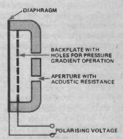
Fig. 6 Diagram of a capacitor microphone.
As the capacitance varies, current from an external source flows in and out of the device, and a signal voltage is developed over a series resistor. The applied voltage tensions the diaphragm, imparting rigidity, and so enabling it to move accurately in response to the sound pressure variations.
The diaphragm has a low mass which gives the advantage of a flat and extended frequency response, free from resonance peaks over its range, and an excellent response to transients.
A disadvantage is the need of a high polarizing voltage, usually about 50V. The capacitance of the transducer is small, around 20-30pF, and so are the variations. Thus the high voltage is required to produce usable output fluctuations. This means that the device has a very high impedance which would cause excessive HF loss over even a few inches of screened cable. To overcome this the preamp is included in the microphone case, receiving its power from the polarizing supply.
This supply must be incorporated in the equipment input circuits; a means for conducting the current must also be provided through the cable. This can take the form of 'phantom' powering, in which one pole of the supply is conveyed along the signal wires through a real or artificial centre tap to the input transformer, and the other pole along the braiding. Another method is A-B powering, where the two supply poles are carried by the two signal wires--these are DC-isolated from each other by capacitors between split windings on the internal output and equipment input transformers.
A further disadvantage is that the microphones and their ancillary equipment are expensive. This is why they are usually found only in broadcast and recording studios, or other professional applications.
There is another method of utilizing the advantages of the capacitor principle without requiring polarizing voltages; this is by using it to tune a small FM radio frequency oscillator and demodulator. The capacitance variations produce frequency modulations which are demodulated to produce an AF output signal. This system is used with Sennheiser capacitor microphones.
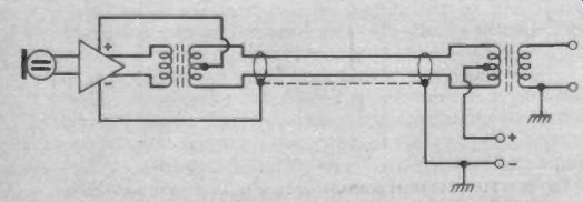
Fig. 7 Phantom powering of a capacitor mike. The supply is sent via the
centre tap on the transformers and the screening.
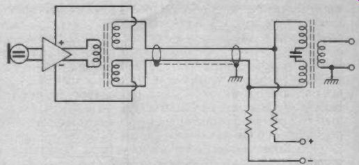
Fig. 8 A-B powering. Both signal wires ares used by means of capacitively-coupled
split transformer windings. This avoids using the screen to conduct current.
Electret: A comparative newcomer to the scene, the electret is a capacitor microphone but with the polarizing charge permanently implanted in the diaphragm. The diaphragm is placed between the plates of an air-spaced capacitor which is charged from a high-voltage source. The diaphragm is heated and then allowed to cool, whereupon the charge is fixed and permanent.
It needs to be thicker than the normal capacitor microphone, which increases its mass and curtails its transient and frequency response. An internal preamp is still required, but this can be a simple two-transistor design operating from a single internal 1V5 cell.
The advantages are a smooth extended response which, although not to the standard of powered capacitor models, is very good and better than most moving-coils. The diaphragm resonance is high (typically 8-10 kHz on the better models), and unlike the mid-range resonance of the moving-coil, this can be tamed with a little treble cut on the tone control. Electrets are light and can be made quite small, making them ideal for the tie-clip units which are favored by many speakers and entertainers. In this case the battery cell can be a pen-torch HP7 housed in the microphone plug, or a small mercury cell in the microphone itself. The current drain is very small (a fraction of a milliamp) and a long battery life can be expected.
A major advantage is cost, as electrets are very inexpensive. Unfortunately this had encouraged many makers to pro duce poor specimens which can give disappointing results. As with capacitor mikes, they are affected by high humidity and can be overloaded by very loud sound sources. Given a good make, the electret has much to commend it for general use and has been found particularly useful for public address work, where the absence of a mid-range resonance enables feedback to be more easily controlled.
Directional Response
The manner in which a microphone responds to a sound field differs according to the operating principles and, of course, is important for choosing the correct type for a particular task.
Omnidirectional: When the back of the diaphragm of a microphone is sealed, there is an isolated body of air trapped in the enclosure, just as in a sealed speaker cabinet. This exerts a fixed pressure against which the diaphragm works. The sound pressure wave is alternately greater and less than the pressure exercised on the back of the diaphragm by the trapped air, so the diaphragm moves backwards and forward. Now sound pressure (like barometric pressure) exerts force in all directions, not only in the direction of sound propagation. So, just as a barometer will indicate pressure of air irrespective of how it is mounted, the pressure microphone will react to sound whether pointed toward the sound source or not.
It is therefore said to be omnidirectional, responding to sounds coming from all directions. This characteristic only holds good up to the frequency where the wavelength is greater than the diameter of the diaphragm. Above this (at shorter wavelengths) the microphone begins to exhibit directional properties. When pointing at 90° from the sound source there are interference effects across the diaphragm, with different parts being affected by different portions of the sound wave at the same time. It can therefore only respond to a limited extent, proportional to the resultant pressure over the whole area.
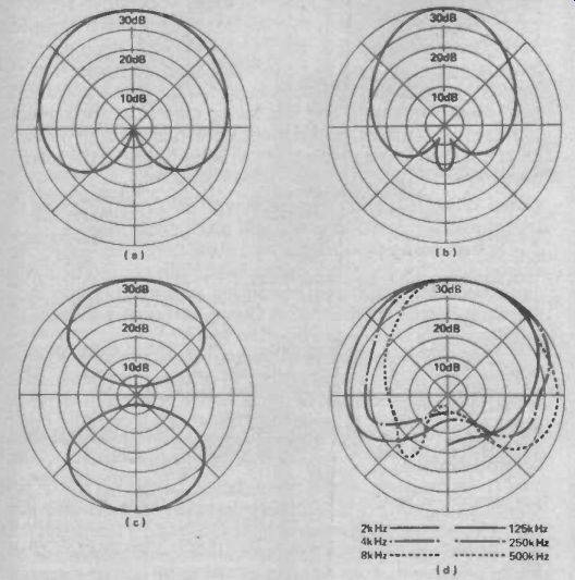
Fig. 9 Polar diagrams of nominal directional response. (a) cardioid; (b)
hypercardioid; (c) figure eight; (d) polar response varies with frequency;
plots are given for six different frequencies.
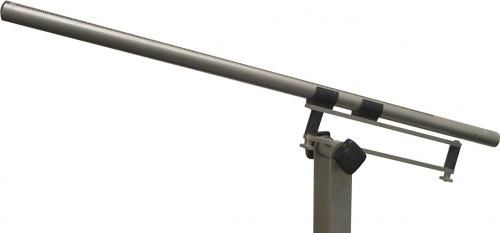
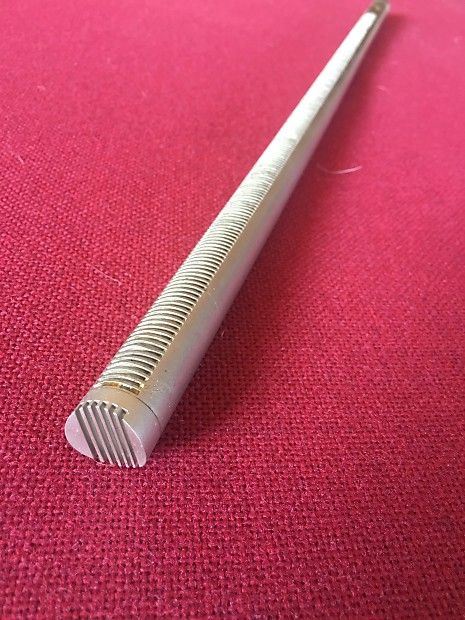
-------- A Sennheiser MKH 816 shotgun-type mike with extreme directionality.
Typical applications are sports broadcasts, studio, film and animal recording.
When the microphone is pointing in the opposite direction to the sound source, the diaphragm is in an acoustic shadow for these short wavelengths, as all objects cast a sound shadow behind them (due to diffraction) when their size is greater than the wavelength of the sound. Hence the microphone response is very low at such frequencies in that position. To give some idea of the frequencies involved, at 1" the frequency is 13.5 kHz, at 1.5", 9 kHz. Most modern microphones have diaphragms smaller than 1" so the effect only occurs at the upper limits of the audio spectrum.
Cardioid: If an aperture is made in the chamber behind the diaphragm so that it is no longer sealed but is open to atmospheric pressure, the mode of operation is changed. Sound pressure is exerted on both sides of the diaphragm which, if equal, would result in zero movement and output. However, access to the rear through vents at the sides of the microphone is restricted so that the pressure is not equal.
Furthermore, the direct action of air molecules moving back and forth along the axis of propagation imparts energy to the front of the diaphragm when the source is situated at the front. Therefore part of the resulting motion is due to the velocity of the air molecules, so the microphone is often termed a velocity type. Pressure differences also are involved so it can be known as a pressure gradient microphone.
When the sound source is to the side of the microphone, similar pressure differences exist between the front and back of the diaphragm but there is no direct impingement of air particles on the front of the microphone. In fact, there can be limited velocity effect on the back of the diaphragm due to dif fraction around the edges of the vent. Hence the output is much lower, with sounds coming from the rear of the microphone being almost completely cancelled and producing very little out put.
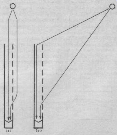
Fig. 10 (a) Sound enters gun microphone from the end and side to arrive
at the diaphragm simultaneously when the source is the front. (b) With
a source at the side, sound paths differ in length. When the difference
is half a wavelength cancellation occurs. This happens over a range of frequencies
due to the different spacing of the holes.
The unit is therefore directional, favoring sounds arriving from the front and progressively rejecting others as the angle from the front increases. When plotted on a circular graph (in which the concentric circles represent the output level) the response resembles a heart-shape--hence the term cardioid.
Hypercardioid: If the acoustic resistance offered by the vents is modified, so that pressure exerted on the back of the diaphragm is increased, the response to sounds arriving from the side is reduced even further, and the directivity increases. The polar response is therefore narrower and becomes a hypercardioid.
One drawback is that the increased rear sensitivity often more than cancels the effect of sounds coming from the rear on the front of the diaphragm. This results in a negative lobe at the rear.
Figure Eight: Ribbon microphones are equally sensitive to sounds coming from the front or rear unless the back of the instrument is deliberately restricted by pads. As they are velocity devices, the response to sounds coming from the sides is zero.
The polar diagram with its front and rear lobes therefore appears like a figure eight. Some ribbon models have been designed to give a cardioid or hypercardioid polar response by using sound guides at the front and suppression at the rear.
Gun Microphone: These use an interference tube in conjunction with a pressure gradient transducer to give a highly directional forward response. The tube is open at the end and has a series of slots or holes running along one side.
When pointed at the source, pressure waves enter the end of the tube and the side holes to arrive simultaneously at the transducer diaphragm. When the source is to one side, the sound follows various paths of different lengths--the shortest being through the hole nearest the transducer, and the longest being via the end of the tube. If the difference between these is half a wavelength, they will cancel and there will be zero pressure exerted on the transducer.
Obviously this happens at only one frequency, but as there is a series of holes there will be cancellation effects for all frequencies within the range of the tube. Cancellation also occurs when the path difference is 1 1/2, 2 1/2 , 3 1/2 (and so on) times the wavelength. Of course there are multiple paths, not just the two that provide cancellation, but being spaced between the critical pair these tend to balance out and produce secondary cancellation.
The tube is only effective at frequencies above the half wavelength value of its total length--below this it reverts to ordinary hypercardioid operation or whatever the transducer mode is without the tube. Some gun microphones have omni transducers, which seems odd since there is no directivity at all below the tube frequency range. Omnis can be identified by having no vents behind the diaphragm. The half-wavelength frequency of a 2 ft tube is around 280 Hz. Directivity increases linearly with frequency.
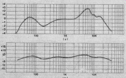
Fig. 11 Which microphone would you prefer, (a) or (b)? A close look at
the vertical calibration shows that the frequency response is the same for
both. Always check calibration when comparing response curves.
Frequency Response
Frequency response is often quoted between two limits, such as 30 Hz-18 kHz. This is useless as it does not specify the levels at which the given limits are measured; they could be at -3 dB, -20 dB or any level in between. Furthermore, they give no indication of the flatness or otherwise of the response. An improvement is to give level limits such as 30 Hz 18 kHz ± 3 dB.
This means that the limit frequencies (and all in between) do not vary by more than ± 3 dB.
Even this is not entirely satisfactory as it does not reveal whether deviations are sharp peaks or broad plateaus, nor their frequencies. The only certain method is the response curve, but even here there are pitfalls. Take a careful look at the vertical calibration; if the divisions are denoting large steps, the curve will look a lot flatter than it really is. The divisions should be in 1 or 2 dB steps, but 4 or 5 dB increments are not unknown and so can be misleading. The actual response required depends on the application, but for most, smoothness is more important than extent.
Electrical Characteristics.
Sensitivity: The output must be sufficient to fully drive the input circuit, otherwise a power amp may not attain full power or a poor signal-to-noise ratio may result in other equipment.
Specifications can be confusing due to the many ways in which sensitivity can be expressed--it stipulates the electrical output obtained for a given sound pressure, and both of these factors can be given in several different units.
Impedance: There are three commonly used impedance ranges; low (30-50 ohms), medium (200-1000 ohms, and sometimes also called low) and high (47 kilohms). High impedance screened cables result in HF losses over all but short lengths, while low impedance is vulnerable to resistive losses over long cable lengths and noise due to connecting plug contacts. It is the medium impedance, 200 ohms in particular, that is commonly used by professionals, and it is taking over from the previous standard of 600 ohms. Impedances in this range match well with most transistor input stages and can be fed without the use of a transformer.
Noise: When placed in a vacuum with no air actuation of the transducer, a microphone will still produce an output. This is due to thermal agitation of the wire in the case of moving-coil or ribbon units; for capacitor microphones it is caused by similar agitation of the diaphragm metalizing, plus irregularities in the supply and noise in the preamp. Owing to the extra sources, the latter generate more noise than the former.
There are several ways of specifying microphone noise--the simplest is the actual output in microvolts. This may be weighted to take account of the nuisance effect that some frequencies have over others. The DIN 45-405 weighting curve, which peaks at between 3-4 kHz and rolls off on either side, is commonly used.
To be meaningful, the noise should be related to the sensitivity, as a given noise level will obviously be more obtrusive with a low signal output than a high. One way of doing this is to convert the noise voltage into equivalent sound pressure--the sound pressure that would produce the same output voltage in that microphone. This may be expressed as a decibel ratio, using the hearing threshold (0.0002 ubar) as the reference level. Alter natively it may be expressed in phons, which is numerically the same as the dB value.
Hum: Moving-coil or ribbon transducers are susceptible to hum when working in strong hum fields. Some have hum-cancelling coils built-in to minimize it. Occasionally the manufacturers a figure which indicates hum sensitivity, the unit being the microvolt per micro-Tesla. The standard field density is 5 uTesla.
Overload and Distortion: Capacitor microphones are the most easily overloaded by loud sounds so a maximum sound pressure is often quoted, 200-300 ubars being a common value.
Lower output models can handle larger volumes, some going to 500 and one even to 1,000 ubars. One model designed for instrumentation applications has an extremely low output that will accept up to 5,000 ubars, a level that would destroy human hearing.
Dynamic microphones (moving-coil and ribbons) are not usually given a maximum sound pressure rating, but they often have a level specified at which distortion will rise to a particular value. This is normally 0.5% THD (total harmonic distortion), but some of the cheaper ones use a 1.0% THD reference. The description usually reads SPL for 0.5% THD = 300 ubars (for example).
There is a tremendous range of microphones now available, making the best choice none too easy. However, if the acoustic and electrical requirements (together with the other features described) are isolated, the selection and subsequent use will be reasonably straightforward.
= = = =
Designers Notebook (Advantages and disadvantages of capacitively-coupled and direct-coupled preamps)