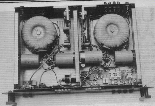
Even hardened DIY types may quail at the thought of tinkering with their expensive commercial hi-fi, but an improvement can often be made simply by beefing up the power supply. Phil Walker discusses PSU requirements and offers a ripple monitor to check whether your supply is up to the job.
Now that Christmas is over and we're looking forward to spring cleaning, perhaps it is time to blow the dust and pine needles out of the hi-fi power supply corner. Is it really up to the job or is it the mud at the bottom of the audio pond? What's in a power supply? Or what SHOULD be in a power supply? Here we examine what steps we must take to determine exactly what is necessary to get the best results out of your audio In order to get anywhere we must first decide or find out what power output is required and into what load impedance we are going to put it. For an existing amplifier these are already defined, so don't be greedy! From these facts we can determine the voltage and current flowing in the load, thus making the estimate of the power supply requirements. From basic theory we have:
V= IxR (Ohm's Law)
P = V x 1 (Power Law)
(V = volts, I = amps, R = ohms, P = watts)
From this we get:
P = V2/R or V = J(P x R)
also P= 1^2 x R or 1 =_/(P/R)
To get an estimate of the peak voltage required we approximate the signal to a sine wave. For this particular case the peak voltage is 42 (or 1.414) times the RMS value given by the above equations.
To go further now we must know what sort of output stage your amplifier has. In general there are three main types.
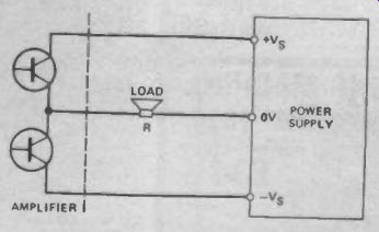
Fig. 1 Split rail power supply configuration.
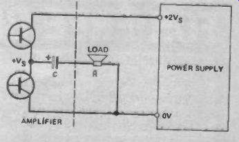
Fig. 2 Single rail configuration.
Split Rail
Each power rail supplies the load voltage and current for approximately half the cycle (Fig. 1.). The voltage required from each rail is:
V = ni(P x R) x + X (X is a factor to account for practical conditions--see later)
The average current required from each rail is:
I = x .12 x 0.6 x 0.5 (The 0.5 factor is because the load current flows for half the output cycle only; the 0.6 factor is because the average of a sine wave is about 0.6 of the peak value)
A reasonably safe approximation for the current is
I = 1/2 x _/(P/R)
Single Rail
The power rail supplies current on the positive half cycle of the signal only (Fig. 2). This drives the load while at the same time recharging the output capacitor C which has previously supplied the negative half cycle of the output signal. The positive end of C in the diagram normally rests at about half the supply voltage when no signal s applied. The supply voltage for this configuration is the same as the total for the split rail version and the voltage and current values found there apply.
Bridge
In this configuration the power supply provides the output current over the whole of the cycle. Therefore the average current is:
I = _/(P/R) (approximated as before)
The supply voltage is effectively switched so that the positive and negative half cycles of the signal are drawn from the same supply rails.
Therefore we have:
V = _/(P x R) _/2 + Y
(Y is a factor to account for practical conditions--not the same as X above.)
What About X and Y?
Well, these are just factors which are included to make up for unavoidable imperfections of practical semiconductor devices. Bipolar and field-effect transistors always drop some volts when conducting and their driving circuits often require even more.
As a general approximation:
for bipolar transistors X = 4 Y=8
and for MOSFETs X = 8 Y=16
What About Class A?

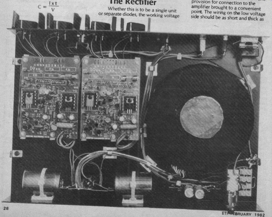
---------Most of the space in this 100 W power amplifier is taken up
by the power supply components--and quite right too!
Up to now we have only considered class B or similar output stages but some people may well have class A amplifiers. If this is the case, the power supply will have to be rated to provide a continuous current 42 or 1.4 times as great as found above.
The Power Supply Transformer
Now that we know the voltage and current required, we can determine what transformer will be required. As a general rule the current rating of the transformer secondary will be the same or slightly greater than the required DC output.
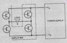
Fig. 3 (Left) Power supply configuration for a bridge amplifier.

Fig. 4 Power supply for single rail and bridge amplifiers.
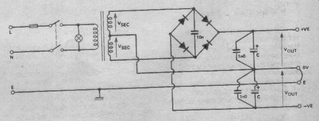
Fig. 5 Power supply for split rail amplifiers.
The voltage rating will be 1/,/2 (0.707) times the required rail voltage plus a volt or two to make up for rectifier losses. The configurations shown in Figs. 4 and 5 are the most usual and will cater for most needs.
For single rail & bridge amplifiers:
V = (Veut + 2)1,12 For split rail amplifiers:
V = (Vou, + 1)/42
The Smoothing Capacitor
The main thing to bear in mind about this component is that the larger its capacitance and the better its quality, the better it will work.
The effect of this component is to reduce the ripple voltages due to the rectified mains and signal frequency currents flowing through it. If either of these currents produce an excessive voltage, the performance of the amplifier is likely to be impaired.
An approximation to the mains derived ripple voltage developed across the capacitor can be found from the basic expression for capacitance:- C = QN (C in Farads, Q in Columbos, V in Volts)
Also Q I x t (I in Amps, tin seconds)
Therefore:
I x t C =
For 50 Hz mains input the maximum time between capacitor charges is 10 ms. (Assuming full wave rectification.) The amount by which the capacitor discharges between charges is the ripple voltage and is dependent on the load current. Rearranging the last equation we have:-I x t V= (t = 10-2 for 50 Hz, full wave rectified) From this it is obvious that C should be as large as possible to keep the ripple small. For example, if the load current is 2 A and we wish to know what the ripple voltage is with a 10,000uF capacitor, we have:
V 2 x 10-2 = 2 Volts (peak to 10,000x 10-b peak)
This about the figure required for a reasonable compromise between cost and effectiveness.
The capacitor should have a ripple current rating of at least three times the DC output current.
The Rectifier
Whether this is to be a single unit or separate diodes, the working voltage for each section must be a minimum of 1.5 times the total secondary voltage of the transformer and for preference three times it. It must have a current rating at least equal to the load current and a surge capability of:-'surge Voc x C t (Isurge in Amps, V in Volts, t = 10 )
Bear in mind that this device may require some form of heatsink when supplying large currents.
Other Points
The rest of the power supply is mainly up to the individual but some things are worth mentioning.
The mains wiring should, of course, be completely safe with no exposed connections accessible even with the covers removed.
A suitable slow-blow fuse, switch and indicator lamp should be included. The mains earth wire should be securely connected to all the metalwork and provision for connection to the amplifier brought to a convenient point. The wiring on the low voltage side should and thick as practicable. The possibility of earth loops must be avoided as far as possible.
The mains input to the transformer may be shunted with a capacitor of 10nF or so, to clean up any high frequency noise on the mains. These must be made for this purpose--250 V sC working or better.
The rectifier bridge may be shunted with a 10nF capacitor of suitable voltage rating to reduce switching noise. It is recommended that the main reservoir capacitors also be shunted with non-electrolytic capacitors of 1 uF or so to reduce their high frequency impedance.
For the best results each amplifier should be fed from a separate supply so that loading on one is not coupled to another.
For the purist, each power rail would be fully regulated and a proper mains filter would be used to eliminate any remaining mains-borne interference.
Power Supply Ripple Monitor
The purpose of this circuit is to continuously monitor the ripple voltage on a capacitor and light an LED if that voltage exceeds about 2 V peak to peak. This will show up those peaks in your program material which cause distress in the power supply and which may be detracting from the overall clarity of reproduction.
Construction
Construction is very simple and straightforward, provided care is taken to ensure that the polarity of each semiconductor is correct.
The PCB is laid out with two circuits in mirror image to allow stereo pairs of amplifiers or single split rail amplifiers to be accommodated easily.
If desired, the polarity of all the semiconductors may be reversed using a BC212L transistor instead of the BC182L.
----------
PARTS LIST
Resistors (all 1/4W, 5%) R1 1k0 R2 10k R3 See Table 1 Capacitors C1 1u0 250V polycarbonate Semiconductors Q1 BC182L ZD1 5V6 400 mW zener ZD2 27v 400 mW zener (required if supply voltage over 35v) LED1 red LED PCB (see Buylines)
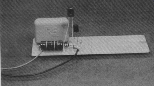
------ The dual ripple monitor PCB with one circuit built onto
it. For use with two mono single rail amps, you can saw the board in
half--or use two boards for a stereo split rail amplifier.
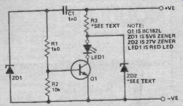
Fig. 6 (Left) Circuit diagram of the ETI Ripple Monitor.

TABLE 1
----------
HOW IT WORKS
The circuit is connected across the reservoir capacitor of the power supply. C1 is normally charged to about the same voltage as the reservoir capacitor and is also discharged by the same amount between charges. If the subsequent recharge is great enough, the current which flows through R1 and R2 will be enough to turn on Q1 hard and illuminate the LED.
ZD1 is a zener diode which provides protection for Q1 base at switch-on and also a convenient discharge path for C1 in normal operation.
R3 limits the current in the LED and in conjunction with ZD2, limits the voltage reaching Q1 collector to a safe value.
---------
= = = =