(source: Electronics World, Aug. 1963)
By JOHN R. GYORKI / Heller's Communication Service
A NUMBER of mobile radio service companies use an automobile batter and a motor-generator combination to furnish the radio test bench with low-voltage, high-current power. Many more shops, however, employ a storage battery and a charger. Few companies, if any, would use just an ordinary low-voltage power supply that converts the 117-volt a.c. line to high-current d.c. The reason for this is that a conventional power supply alone usually has very poor voltage regulation for current demands that fluctuate heavily when the transmit button of the radio is depressed and released. Also, the output impedance of the power supply is normally high compared to that of a storage battery. A regulated low-voltage, high-current power supply could be purchased, but it would be comparatively expensive and the application may not warrant such an outlay.

--------A simple transistorized series regulator is employed along
with a conventional auto regulator.
The automobile storage battery and charger combination is probably the most popular with service technicians. The charger is connected to the battery and then turned on when a radio is put on the bench to be serviced. After the radio is repaired and disconnected from the source, the charger is allowed to run for awhile to bring the battery up to par again.
Then the charger must be turned off and the battery disconnected so that it will not discharge back through the power supply. The nuisance of watching over a battery so it will not become overcharged and disconnecting it so it will not discharge, can be eliminated by using an ordinary automobile voltage regulator in the manner to be described.

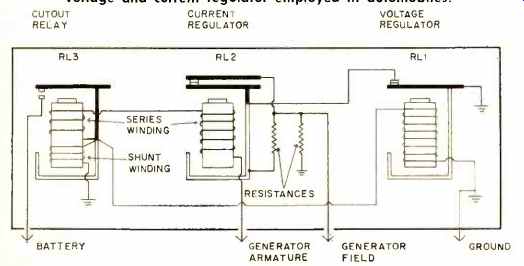
Fig. 1. Circuit diagram of a conventional triple relay voltage and current
regulator employed in automobiles.
Standard Voltage Regulator
The standard voltage regulator ( Fig. 1) consists of three major components. The first of these is the cutout relay, RL3.
This relay is normally open when the engine is idling slowly or not running at all and prevents the battery from discharging back through the generator. When the engine is running and the generator output starts to build up, the current goes from the generator through the series and shunt coils to ground and energizes the relay; connecting the generator to the battery. The second relay, RL2, is the vibrating current regulator which controls the output current of the shunt-wound generator. This regulator keeps the current output of the generator within safe limits since a shunt-wound generator does not have any inherent current limiting features.
The third component is the vibrating voltage control relay, RL1. Spring tension on the armature of the voltage regulator relay holds the contacts closed until the generator output reaches a predetermined voltage. As the voltage approaches this value, the current through the coil winding magnetizes the core sufficiently to draw down the armature, thus opening the contact points. This inserts resistance in series with the field winding and reduces output voltage.
A bimetallic hinge is usually employed on the regulator armature so that more voltage will be required to open the contact points in cold weather since a higher voltage is necessary to charge the battery in cold environments.
Transistorized Voltage Regulator
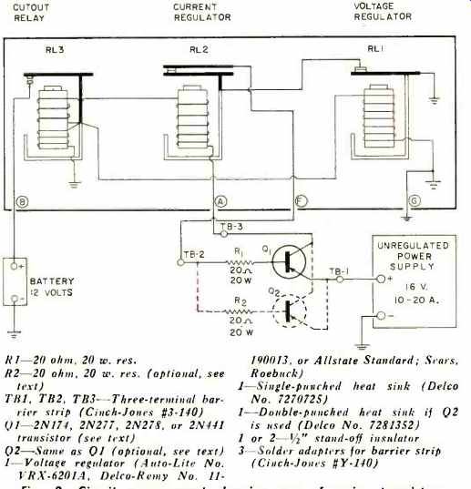
The transistorized electromechanical voltage regulator is simply a conventional automotive regulator wired to a transistor circuit which takes the place of the generator field function. See Fig. 2. It is used with an ordinary unregulated power supply or a battery charger and a 12-volt storage battery. The voltage and current regulator relays of the standard regulator control the field current of the generator by adding resistance to the normally grounded end of the field circuit. The resistors found on the original regulator must be removed in the transistorized application since the relays will now be used to control the base current of a power transistor.
The cutout relay operates the same in the transistorized system as it does in the automobile. When the power supply is turned on, current flows through the series and the shunt windings. The two resulting magnetic fields act in the same direction and add to pull down the relay armature, connecting the battery to the power supply through the transistor.
When the power supply is shut off, the battery voltage being higher than the supply voltage (charge left in the filter capacitors) , a reverse current flows from the battery to ground in the shunt winding and from the battery to the power supply to ground in the series winding. These two currents will now produce opposite poles in the core of the cutout and the magnetic pull on the relay armature arrests, opening the circuit so the battery will not discharge back through the power supply.

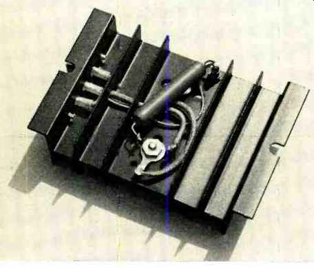
-- Underside of the transistor heat sink showing placement of the base
bias resistor. Note wiring to insulated terminal board.
The current regulator, RL2, limits the maximum amount of current flowing out of the power supply. The full charging current going to the battery must pass through the current regulator coil winding. This current sets up a magnetic field and a pull on the relay armature. If the current ( and resulting magnetic pull) is in excess of that for which the armature tension is set, the relay opens, disconnecting the transistor base from ground and shutting off the current going to the battery. As soon as the circuit is open, however, the regulator field collapses and the relay snaps back. This, in turn, sets up a field again and the process is repeated from 150 to 250 times per second. This action serves to keep the power supply from exceeding its maximum rated current capacity.

Fig. 2. Circuit arrangement showing use of series transistor.
For doubled current output, a second transistor may be employed.
The voltage regulator, RL1, controls the maximum battery terminal voltage. When the battery voltage reaches some predetermined voltage during charge (about 15 volts) , the current in the shunt winding builds up enough magnetic strength to pull the relay armature down against the spring tension. This opens the base circuit of the transistor and shuts off the charging current. When the battery voltage decreases slightly, the magnetic field weakens and allows the contacts to close again. This turns on the transistor and permits the power supply to charge the battery again. This cycle is repeated from 50 to 200 times per second to cause the armature to vibrate and so hold the voltage to a reasonably constant value.
-------

Construction details of a simple series regulator circuit that is designed for use with unregulated bench supply or charger and storage battery. Employed for mobile radio servicing.
--------
When the power supply is turned on and RL1 and RL2 contacts are closed, about 600 ma. of base current flows; the transistor is now "turned on" or saturated. The collector-to-emitter impedance is very low (about .080 ohm) and maximum collector current (charging current) flows. When either RL1 or RL2 contacts open, however, due to excessive voltage or current, there is no base current flow and the transistor is "turned off" or cutoff. The collector-to-emitter impedance is very high; approaching that of an open-circuit condition.
RL1 can be adjusted over a range of voltages by changing the spring tension on the relay armature. RL2 should be adjusted to limit the collector current to 10 amperes when one transistor is being used. If more charging current is required, another transistor (Q2) can be connected, as shown in Fig. 2 in dotted lines. Two transistors can handle a current of 20 amperes, providing the power supply being used is capable of coping with 20 amperes at 16 volts d.c.
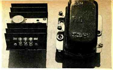
The regulator shown in the photographs was constructed for a charging current of 5 amperes at 16 volts. The transistor should have a collector current rating sufficient to handle the desired charging current. The one shown is a 2N174.
However, a 2N277, 2N278, or a 2N441 power transistor may be used. Even some "bargain" transistors can be used in most cases since the maximum collector-to-emitter voltage is 16 volts or less.
When mounting the transistor on the heat sink, a little silicone grease should be placed between it and the heat sink for best thermal conductivity. The heat sink is electrically connected to the collector of the transistor so care should be taken to see that nothing of a different potential may short up against it.
The heat sink has an area of about 80 square inches and has a three-terminal barrier strip installed at one end for connection to the transistor emitter, base resistor, and collector. The base-bias resistor is placed under the heat sink by means of an insulating stand-off terminal, as shown in one of the photographs. The heat sink is mounted vertically under the test bench alongside the conventional automobile voltage regulator.