At different prices one expects to find variations in terms of design, construction and performance in amplifiers. Also, there may be differences attributable to the purposes which the tape recorder is intended to serve; not every tape recorder is meant for high-fidelity service. Since it is not feasible in these pages to examine all types of amplifiers, the most informative approach appears to be to deal with the kind of amplifier capable of yielding top performance in audio work.
Electrical performance In terms of electrical performance, a tape amplifier should meet high-fidelity standards with respect to frequency response, distortion, signal-to-noise ratio and equalization. Moreover, it should have sufficient gain to accommodate various input signals as well as to drive following audio components in playback.
Frequency response In terms of electrical performance-prior to the speaker--a high fidelity system should span the range of at least 20-20,000 hz with a tolerance of about ± 0.1 db. However, this frequency requirement must be modified in the case of a tape recorder, the extent of modification depending upon tape speed. The lower the speed, the less can reasonably be expected in the way of high frequency response. Low-end response, however, varies relatively little with tape speed.
The present state of the art of tape recording, which takes into account the characteristics of the tapes and heads now available, permits fairly smooth response to be obtained out to 15,000 hz at speeds of 7.5 ips and higher. Such extended response at 7.5 ips, however, involves sacrifices in terms of distortion and/or signal-to-noise ratio. In the case of amplifiers that incorporate substantially all available means of reducing noise and distortion, the amount of such sacrifice still permits high-fidelity performance while maintaining substantial response to 15,000 hz. In amplifiers of lesser grade, maintaining response to 15,000 hz can en tail a serious degradation with respect to distortion and signal to-noise ratio.
In the experience of many listeners there is virtually no difference to the ear between a response nearly flat (no more than 2 db down) to 12,000 hz and response virtually flat to 15,000 hz. Moreover, above 10,000 hz, audio sources such as phonograph discs, tuners, recorded tape, etc. often contain noise and distortion components equal to or exceeding the desired audio information. At 7.5 ips, the speed predominant in home use, lowering the requirements to 12,000 instead of 15,000 hz often permits a significant improvement in signal-to-noise ratio and/or distortion. Thus, a tape amplifier to be used in conjunction with top-flight heads at the 7.5-ips speed should provide response virtually flat to 12,000 and possibly to 15,000 hz.
The 3.75-ips speed is also very common in home use. Attain able high-frequency response varies directly with tape speed so that at 3.75 ips the tape amplifier in conjunction with the heads should be able to provide response to 6,000 hz and perhaps to 7,500.
At 15 ips, used by professionals and home recordists who seek the utmost in quality, response should extend to at least 15,000 hz. Higher response has relatively little value and it is generally advisable to sacrifice response above 15,000 hz, to improve the signal-to-noise ratio and reduce distortion.
At the bass end, taking into account head and tape characteristics, the amplifier should provide equalization which assures response no more than 3 db down at 50 or possibly 30 hz. It may well be asked why it would not be better to require flat response down to 20 or 30 hz, especially since speaker systems reproducing satisfactorily down to 20 or 30 hz are becoming more common. The answer lies mainly in the large amount of low-frequency equalization which would be required in playback, accentuating low-frequency noise (and hum frequencies) and thereby deteriorating the signal-to-noise ratio. Thus, the present NARTB standard of tape-recorder frequency response applicable to 15-ips recording covers the range from 50 to 15,000 hz and permits response 4 db down at 50 hz. If a tape recorder is 3 db down at 30 or 50 hz, this does not necessarily mean a sharp cutoff below this point; there can still be usable output, perhaps 6 to 8 db down, at 20 hz.
Uniform frequency response over the feasible range is important. Audible peaks should not be present. On the other hand, in view of the complexities of equalization, a standard of ±1 db permissible deviation from flat response within a prescribed range, while desirable, is somewhat rigorous, especially since equalization requirements tend to vary somewhat from one tape to an other even within the same brand. Quite acceptable reproduction of the original sound can be had if the tolerance is ±3 db. Response flat within ±2 db is barely distinguishable from the original to the human ear and may be considered a suitable standard, although a few of the professional recorders when carefully adjusted manage to stay within ±1 db. If a listener moves to another seat or turns his head slightly, the resulting change in relative frequency response over the audio spectrum is much greater than the ±2-db deviation due to the tape recorder.
Many tape recorders are designed to operate at two speeds, usually 7.5 and 3.75 ips for home use and 15 and 7.5 ips for professional use. To the extent that economy is an important factor, it is difficult for an amplifier to serve both speeds with equal faithfulness. If a sacrifice is required at one speed or the other with respect to frequency response, it is logically consistent that performance at the higher speed should be given preference for it is the higher speed that also provides superior results in terms of signal-to-noise ratio and distortion.
Distortion In recording, the determining factor with respect to distortion should be the tape, although a poorly designed record head can overload before the tape does, particularly at low frequencies.
In any case, the record amplifier should produce no appreciable distortion.
Maximum permissible record level is customarily the 400-hz signal level which produces a given amount of harmonic distortion, sometimes given as 1%, sometimes as 2% or as 3%. The...
[…missing content: pages 32-33 ]
...quently, the record amplifier should have hum and noise characteristics as good as those of the playback section.
All in all, in a well-designed and well-constructed tape recorder, the dominant cause of noise should not be the amplifier or the heads (which would be adequately shielded against hum) but the tape itself, which has inherent noise that cannot be eliminated.
A signal-to-noise ratio of 55 db may appear low as a measure of high-quality performance in a tape recorder, particularly when compared with ratios of 70, 80 or 90 db claimed for other audio components, particularly power amplifiers. On the other hand, it is not particularly low when compared with ratios for other audio sources in light of the problems in tape recording.
The magnetic phono channel of most control units provides a signal-to-noise ratio in the range of 50 to 60 db, which is comparable to the 55 db of a first-rate tape recorder. Yet the phono channel of the control unit has an easier task than the playback section of the tape amplifier. Peak output from magnetic cartridges usually ranges from about 30 my (millivolts) to as high as 100. Compared with the 10 my or so peak output from a play back head, this is a difference of at least 10 db. Moreover, a tape amplifier that conforms to NARTB equalization must produce a relatively enormous amount of bass boost. Equalization for disc recordings generally requires bass boost starting at 500 hz, but in the tape playback amplifier bass boost starts at 3,180 hz (NARTB equalization). The tape playback amplifier has a total boost of 36 db when NARTB equalization is used whereas the phono channel incorporates but 20 db of boost when compensating the RIAA recording characteristic now almost always employed for discs.
Turning to the FM tuner, a transmitting station is considered excellent when its transmitted signal has a signal-to-noise ratio of 55 db. The best FM receivers have a ratio of 55 to 60 db.
In discussing the tape recorder's signal-to-noise ratio, it was presumed that the playback head is of the full-track variety commonly, though not always, used for professional quality. How ever, if a half-track playback head is used, as in most home recorders, the tape recorder may have a somewhat lower signal to-noise ratio inasmuch as a full-track head (assuming full-track recording) has about 8- or 9-db higher output. However, the difference between half- and full-track heads with respect to signal to-noise ratio is likely to be closer to 3 or 4 db since the full-track head picks up more tape hiss and more hum as well as more audio signal. Thus, a tape recorder using half-track heads may be considered as having a good signal-to-noise ratio if this exceeds 50 db.
Equalization
Without question, a top-quality tape amplifier intended for high-fidelity service should incorporate equalization that conforms to present accepted standards, whether or not these standards are official. Thus the tape recorder can produce tapes that sound right on other machines and, conversely, it can sound right when playing tapes made on other machines. The latter requirement is the more important one because a tape recorder may be used to reproduce some of the excellent prerecorded tapes reaching the market in increasing numbers.
How accurate should equalization be? The answer is essentially the same as with respect to uniformity of frequency response.
Thus a deviation of ±2 db over the range of 50 to 15,000 hz at 15 ips, 50 to 12,000 hz at 7.5 ips and 50 to 6,000 hz at 3.75 ips can be considered good.
A substantial number of machines, particularly the moderate price ones, shy away from maintaining response so that it is no more than 3 db down at 50 hz. By allowing the response to drop substantially at the low end, problems of hum and noise are significantly reduced. Similarly, many recorders do not at tempt to extend the high end because this requires improvements with respect to distortion and noise that the price of the machine does not permit.
Most tape recorders operate at two speeds, a few at three. Each speed requires substantially different equalization in the record section of the amplifier while there may or may not be a substantial difference required in the playback amplifier, depending on the speed involved. The 7.5- and 15-ips speeds often employ substantially the same playback equalization, while 3.75 ips requires considerably different equalization.
A high-quality tape amplifier permits changing equalization according to speed. Too often, however, amplifiers do not contain such switching facilities. Therefore, response may be perfectly satisfactory at one speed but not at the other or, inasmuch as some machines use a compromise equalization, response at neither speed may be as good as possible.
Extended treble response at the lower speeds, 3.75 and 7.5 ips, is feasible, at least to an extent, through very substantial amounts of treble boost in the record amplifier. However, this entails the risk of increased distortion because of the extent to which the high frequencies are boosted. Therefore a high-quality amplifier will follow a course of moderation, avoiding treble boost which attains a slight improvement in treble response at the cost of a large increase in distortion.
Gain
The tape amplifier should have sufficient gain to accommodate various audio sources when recording and to furnish the required driving signal to either a control unit or a power amplifier in playback.
Virtually all high-level signal sources-control units, radio tuners, TV sets, and ceramic and crystal phonograph cartridges have peak outputs of at least 0.5 volt. Thus a tape amplifier which can be driven to full record level by an 0.5-volt input might be sufficient. However, there should be a margin to allow for the occasional so-called high-level source which does not pro duce 0.5 volt on peaks. Also the reserve should allow for the fact that tapes of the near future, for the same amount of distortion, may be able to accept more signal from the record head with correspondingly greater tape output. Allowing about 10 db of re serve, this means that the input sensitivity of the amplifier should be on the order of 0.1 to 0.2 volt.
For low-level sources, a sensitivity of at least 1 to 3 my is required. A typical dynamic microphone at a distance of 2 feet produces about 2-mv output when driven by a human voice at average level. Peaks and loud tones produce considerably greater output. Thus a sensitivity of 1 to 2 my appears adequate.
Most control units can be driven to their rated output by in put signals below 0.5 volt, often by as little as 0.1 volt. Power amplifiers generally can be driven to their rated output by signals varying from 0.5 to 2 volts. However, seldom is a tape recorder fed directly into a power amplifier. Accordingly, a tape recorder with a peak output of 1 to 2 volts should meet virtually all practical requirements so far as high-fidelity and other audio systems are concerned.
If the tape amplifier has much greater input sensitivity or higher output level than is required, this is not necessarily a virtue. Excessive gain may mean excessive noise from stages following the volume control, either in record or playback. Excessive gain may involve problems of stray feedback and consequent oscillation.
Excessive tape-recorder output may overload the following control unit, particularly if the control unit does not have a "level- set" potentiometer which permits cutting the input signal to a level that will avoid significant distortion.
Mechanical features
The mechanical features of a tape amplifier are related in part to its electrical performance, convenience of operation, durability of the amplifier and minimization of servicing requirements.
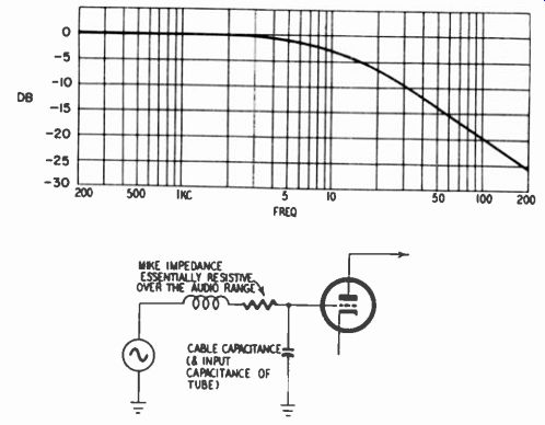
Fig. 201. Typical high-frequency droop due to cable capacitance when
using a high-impedance microphone.
While electrical performance is first in importance, it is no small thing to the recordist to have those features which provide ease of recording, editing, etc., reduce the chance of the recording going awry and which insure long and reliable service.
Inputs
Virtually every tape amplifier has at least two inputs, one for high-level sources and the other for low-level, specifically micro phones. In moderate-price recorders the low-level source accommodates only high-impedance microphones, which have an impedance in the order of 5,000 to 50,000 ohms. This is no great disadvantage so long as cable length is less than 15 feet or so.
Longer cables, however, have sufficient capacitance so that, in conjunction with the input capacitance of the tube, they act as a serious shunt at frequencies in the audio range (Fig. 201).
To permit long cable runs, many microphones, particularly professional ones, are of the low-impedance variety, usually in the range of 50 to 250 ohms. These, however, have much lower voltage output than do high-impedance units and require a transformer to bring their output up to the level of the latter. The professional tape recorder usually either contains one or incorporates a socket for plugging in an accessory transformer of this kind.
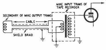
Fig. 202. Balanced microphone-cable connection.
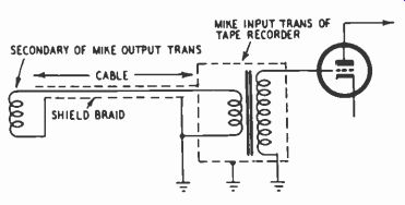
Fig. 203. Unbalanced microphone-cable connection.
Where cable runs are of substantial length, using a low-impedance microphone, the cable connection to the tape amplifier is often of the balanced type (Fig. 202) which cancels out, with respect to ground, hum and noise (fluorescent lights, static, etc.) picked up by each cable lead. Fig. 203 shows an unbalanced connection between microphone and input transformer, which is more susceptible to hum and noise pickup.
Outputs
In moderate-price tape recorders, high-impedance outputs ranging from 100,000 ohms to 1 megohm are usually the rule, resulting in high-frequency losses between the recorder and following audio equipment if more than a very few feet of cable are used.
Losses occur for a reason similar to that represented in Fig. 201.
Consequently, the better amplifiers provide a low-impedance output so that fairly long cables can be used. This may be a cathode-follower output, having an impedance of several hundred ohms, which should be fed into loads of at least 10,000 ohms, and preferably 100,000. Or it may be a transformer output having an impedance of 600 ohms, which is standard in much professional audio equipment; equipment designed to accept signals from a 600-ohm source will seriously load down a high-impedance source.
Most tape recorders provide an output jack so that high-impedance headphones may be inserted for monitoring. In a tape amplifier with separate record and playback sections, the monitoring jack is placed across the regular output jack so that the monitor may hear whatever signal comes from the recorder, which may be either the incoming signal or the playback signal from the tape. In a tape recorder with a common record and playback amplifier, the monitor jack customarily is connected to a late record stage although in some cases it may also be connected across the output when the amplifier is switched to playback.
Mixing facilities
Although some tape recorders permit both a high-level (tuner, control unit, etc.) and low-level (microphone) signal to be recorded simultaneously, only the more elaborate recorders provide individual gain controls for each source. If but one gain control is available, the level must be set for microphone input and the level of the other signal must be set at the source. Ordinarily this cannot be done at the control unit because the signal level fed to the tape recorder usually (and properly) is independent of the control unit's volume control. Thus it may be necessary to add a mixer between the control unit and the tape recorder amplifier.
A-B comparison
One of the principal advantages of a tape recorder employing separate record and playback heads and separate amplifiers is that it permits immediate checking of the quality of the recording.
To facilitate this check, the recorder incorporates an A-B switch which connects the output to either the incoming signal (A) or the tape playback (B). By rapid switching between the two signals, the listener can readily tell whether the recording is a reasonable facsimile of the original.
Although a switch is ordinarily used for A-B comparison, another technique is to use a fader consisting of a potentiometer which has its center point connected to ground. On one side of center, the arm of the pot picks up the incoming signal from the record preamplifier while on the other side it picks up the play back signal. Whereas the fader gives the listener control over the level of either signal he wishes to hear, the switch permits the ear to transfer immediately from one source to the other so that the comparison is sharpened by the absence of a time interval.
Metering facilities
Every tape recorder has a means of indicating to the operator the proper record level so that he may avoid excessive distortion and yet record at a level high enough to produce a satisfactory signal-to-noise ratio. For best results a meter is considered prefer able to the electron-ray-tube (magic eye) and neon-light indicators.
Where a record-level meter is employed, provision is usually made for calibrating the meter so that it accurately indicates permissible record level as determined by maximum acceptable distortion. Calibration may vary with the type of tape.
A record-level meter is customarily, though not always, used for two other purposes: measuring bias level and tape output.
Correct bias setting is vital in obtaining a satisfactory combination of low distortion, high signal-to-noise ratio and wide frequency response. The meter can be used in setting bias for optimum results and is valuable as a means of speedily checking whether bias is at a level previously determined to be correct.
When the meter is used to measure the signal level recorded on the tape, this can show whether too high a recording level was employed in making the tape, thereby indicating the source of distortion, if such is discernible. Measurement of tape output can be important in setting the playback gain to provide the correct amount of signal to following audio equipment.
Alignment facilities
Seldom do moderate-price tape amplifiers permit ready adjustment of bias. If a meticulous operator does wish to adjust bias for optimum performance, it is necessary to change the value of either a resistor or capacitor. Professional and semiprofessional amplifiers incorporate a potentiometer or variable capacitor for adjusting bias in accordance with the manufacturer's instructions.
Similarly, equalization is usually fixed in moderate-priced recorders and variable in professional ones. Adjustable record treble boost and playback bass boost permit the operator to make his machine conform to standard equalization. Sometimes, vari able treble equalization is also included in playback to compensate for losses in the playback head. However, in some tape recorders the quality of the heads is such that response is quite satisfactory without compensation of playback-head losses.
When a meter is employed to measure record level, output and bias, it is desirable that facilities be included for calibrating each function. Optimum bias should correspond to a well-defined point on the meter, usually zero in the case of a VU (volume unit) meter.
If the tape amplifier has ac on the tube heaters, a hum-null potentiometer (Fig. 204) is a desirable feature. Most home recorders use ac on the heaters and to cancel hum they ground the center tap of the heater winding on the power transformer (Fig. 205). However, the center of the winding may not be the best point for balancing out hum; a potentiometer as shown in Fig. 204 can do a more effective job.
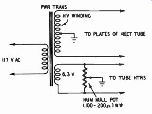
Fig. 204. Hum cancellation by use of a hum-null potentiometer.
Layout and components
However good the electronic design of a tape amplifier may be, its successful transformation into high-quality performance depends upon careful layout and use of high-quality components.
Proper layout must provide accessibility for servicing, minimize heating of vital parts and avoid hum pickup at susceptible points.
Both the record and playback sections of the amplifier are high-gain circuits and stray feedback can produce oscillation, quite possibly outside the audio range. Although inaudible, oscillation can prevent proper operation of the amplifier or associated audio components. Another possible difficulty is stray pickup of bias current. This can affect the meter indication of record level and can increase bias current supplied to the record head above the proper level.
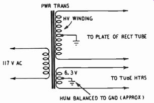
Fig. 205. Hum cancellation by grounding the heater winding.
A well-made amplifier, at a moderate increase in cost, uses resistors and capacitors overrated in terms of wattage and voltage.
This not only cuts down service needs but also insures stability of operation because parts subject to overheating or excessive voltage stresses may change value or break down. Off-value components can affect bias current which in turn means affecting frequency response, distortion and signal-to-noise ratio. They can affect equalization circuits and therefore frequency response and they can affect meter calibration and signal-to-noise ratio.
A high-quality amplifier uses low-noise resistors, either of the deposited-carbon or wirewound type, in early stages, which largely govern amplifier noise. Capacitors should be of good manufacture and as free as possible of leakage, and should avoid excessive departure from nominal value.
Miscellaneous mechanical features
One of the chief bugaboos of the recordist is that the tape amplifier may accidentally be in record position when it is desired to play a valued tape, resulting in accidental erasure. Two pre cautionary devices may be used to prevent this. One is a mechanical lockout which prevents switching the amplifier into record position without pushing or depressing an auxiliary lever or button. However, it is possible that the tape to be played may be placed on a machine which was left in the record position. Thus as a further safeguard the recorder should have a warning light that glows commandingly whenever the unit is in record position.
The amplifier should contain at least one switched ac power outlet for supplying current to the transport. One or more additional switched outlets are desirable for supplying power to such equipment as a mixer, a second-channel amplifier for stereo purposes, etc.
Illustrative amplifiers
Fig. 206 presents front and back views of a typical high-quality tape-recorder amplifier that is used in the Concertone Series 20.
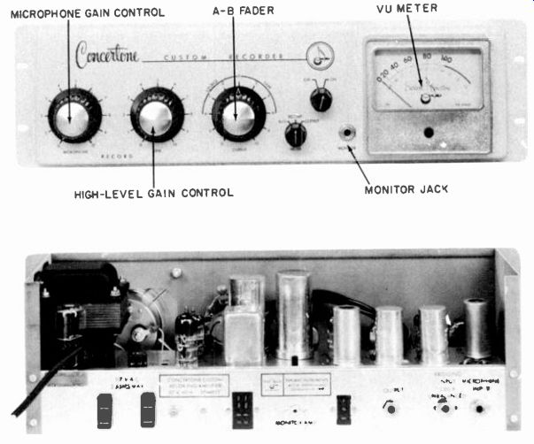
Fig. 206. Two views (front and rear) of a tape recorder amplifier. (Courtesy,
American Electronics, Inc.)
On the front panel, from left to right, are the following: (1) microphone gain control; (2) line or high-level gain control; (3) A-B fader, which feeds either the incoming signal or the tape playback to the output and also determines the output level; (1) switch for employing the VU meter to measure record level, output level or bias; (5) off-on power switch; (6) monitor jack for headphones; (7) VU meter.
On the rear panel, from left to right, are: (1) two switched ac power outlets; (2) record-head jack; (3) monitor jack; (4) play-back-head jack; (5) the output jack; (6) the line input jack; (7) microphone input jack. Above the chassis (not visible) there are:
(1) a control for calibrating the meter so that it reads 100 at correct bias; (2) a pot for setting bias level; (3) a socket for plugging in an output transformer to obtain 600-ohm balanced output (center tap to ground); (4) an input transformer socket which permits feeding a low-impedance microphone into the low-level jack.