AMAZON multi-meters discounts AMAZON oscilloscope discounts
The advantages and disadvantages of vacuum-tube versus crystal probes were discussed in an earlier section. Although in recent years crystal probes have achieved considerable acceptance for servicing work, vacuum-tube probes are still widely used.
The length of time it takes for electrons to travel from the cathode of a tube to the plate is known as transit time. Transit time becomes important when you start working in circuits operating at frequencies of approximately 50 mhz or higher. The relationship of such high frequencies to transit time can cause a phase shift between plate current and grid voltage and can result in a change in the input conductance of a tube. There are other modifications that will take place in the characteristics of the probe tube, to such an extent that the voltage output of the probe will not be a true measure of the signal being tested.
For these reasons, transit time imposes a limitation on the high-frequency range of vacuum-tube probes. The practical, up per-frequency test limit can be extended by using miniature diodes designed for work at very high frequencies.
Contact potential
It is quite possible for a very small current to flow from the cathode of a vacuum-tube diode to the plate, even though the plate is not connected to any source of B plus voltage. If this cur rent is as small as 0.1 ma, it will produce a potential of I volt when flowing through a 10,000-ohm resistor, The effect of this current is to make the plate of the diode negative (by 1 volt in this instance) with respect to the cathode. This means that if the diode is used as a probe, the incoming signal must have a peak value of more than 1 volt before it can make the plate of the diode positive with respect to the cathode. This reduces the sensitivity of the diode, since there are times when you will wish to measure potentials smaller than 1 volt.
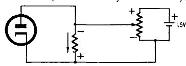
Fig. 1001. Basic circuit for overcoming the effect of contact potential.
In Fig. 1001 a resistor is shown connected between the plate and cathode of a diode. The flow of current due to contact potential is in such a direction (as shown by the arrow) that the top end of the resistor is negative. Since this resistor is in parallel with the diode, the voltage and the polarity between plate and cathode of the tube are the same as that across the resistor.
To overcome the effect of contact potential, an opposition or bucking voltage is applied to the diode. In Fig. 1001 we have a 1.5-volt cell shunted by a potentiometer. Note that the polarity of the voltage across the potentiometer is in opposition to that developed by the load resistor across the diode. With the proper setting of the potentiometer the contact voltage developed by the diode is neutralized, the diode then becoming responsive to small signal inputs. The bucking voltage can be taken from a voltage divider tap in the v.t.v.m. Some probes use a duo-diode, one-half of which is used to rectify the signal being tested, the other half of the tube supplying the bucking voltage.
High-frequency probe
You can use a high-impedance, vacuum-tube type rectifier probe for measuring high-frequency voltages. The tube in the probe housing rectifies the high-frequency a.c. voltage under test to a proportionate d.c. value and feeds this voltage to a v.t.v.m.
The circuit of a typical high-frequency probe (often called an r.f. probe) is shown in Fig. 1002. The probe is a peak indicating type. Its d.c. output has value approximately equal' to the positive peak voltage of the a.c. applied to the tip of the probe. Basically, this relationship between the a.c. input and the d.c. output of the probe is true only when the rectified probe output feeds into an infinitely high d.c. load resistance.
The input of a vacuum tube (control grid-cathode circuit) is a suitable load. Since the input resistance of a v.t.v.m. is less than infinite, the rectified output of the probe is never quite truly equal to the full peak a.c. input to the tip of the probe. However, the difference is small enough to permit calibration on the basis of true positive peak voltage.
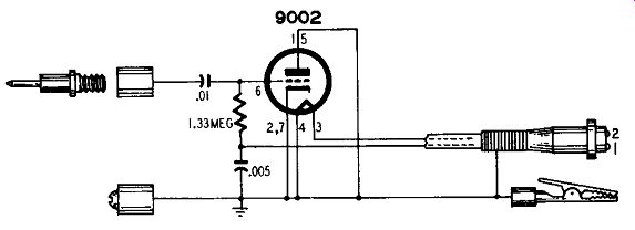
Fig. 1002. Peak-indicating high-frequency probe (r.f. probe). The tube is
connected as a diode.
As shown in the circuit diagram (Fig. 1002) the probe uses a 9002, diode-connected. Another tube type that is used is the 1247. A certain amount of contact potential will be noted, particularly if your v.t.v.m. is set to read between 1 and 3 volts d.c., full scale. If contact potential produces a deflection on your v.t.v.m., simply rotate the zero-adjust control until the meter needle is back to zero. Contact potential decreases in nuisance value when you measure voltages of 10 or more. For such checks, contact potential will barely disturb the original zero setting of your v.t.v.m.
The relationship between the true peak voltage at a test point and the meter reading on the d.c. scale of the v.t.v.m. is shown in Fig. 1003. This graph also indicates that the useful working range of the probe is between 0.2 volt and 200 volts peak, approximately. These are low- and high-frequency a.c. voltage values commonly encountered in the servicing of radio and TV sets.
Voltage measurements in high-frequency, high-impedance circuits usually cannot be made with a low-impedance a.c. measuring instrument such as a multitester having a sensitivity of 1,000 ohms per volt. Such tests must be made with a suitable high-impedance test instrument. The probe that is used should be specifically designed to yield the greatest over-all accuracy in the high-frequency a.c. spectrum. Measurements at low frequencies, how ever, can be satisfactorily done with the usual multitester.
The d.c. output of the probe whose circuit appears in Fig. 1002 is negative with respect to ground. If you have a center reading v.t.v.m., this means that the meter needle will swing left.
Some v.t.v.m.'s have a plus-minus control whose setting permits the needle to move in a forward direction, regardless of the polarity of the d.c. input voltage .
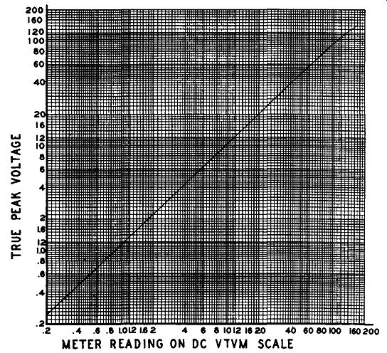
Fig. 1003. Graph shows relationship between peak voltage at test point and
meter reading on your v.t.v.m.
Ground leads
Although we have mentioned the importance of short ground leads in various places throughout this guide, it is once again forcibly emphasized in the construction of this probe. If you will examine the photo (Fig. 1004 ), you will see that there are two ground connections on the probe. One of these is a ground stud mounted directly on the probe head. In addition, a flexible lead terminates in an alligator clip which extends from the rear cap of the probe. This flexible lead should be used only when measuring relatively low-frequency voltages. All high-frequency measurements should be made using as short a lead as possible connected to the ground stud on the head of the probe. The use of this stud provides a much shorter ground connection, minimizing both the ground return loop and the degree of input capacitance which will be shunted across the circuit to be measured when the probe is applied.
The capacitance of such probes, even though kept to a very low value, can still be sufficiently great to detune resonant circuits Fig. 1004. Probe comes equipped with two grounding points. The stud on the probe head should always be used when malting tests in high-frequency circuits, using a low C to L ratio. Whenever you make measurements in resonant circuits, return the circuit to resonance with the probe point making contact before you take a final reading on the meter.
If you do this the additional shunt capacitance introduced by the probe will be satisfactorily minimized. After the probe has been removed and your checks are completed, the circuit tuning slug or trimmer capacitor can be returned to its original position.
Another commercial type of high-frequency or r.f. probe is shown in Fig. 1005. This probe uses a 1247 subminiature tube type. The special design of the tube makes possible a compact probe that provides a flat frequency response to 300 mhz and which is usable to 500 mhz. The probe has an input rating of 300 volts and a high input impedance of 2.3 megohms with only 3-µµf input capacitance.
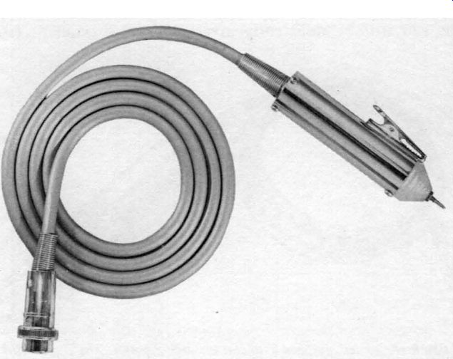
Fig. 1005. This r.f. probe uses a subminiature tube. The clip, fastened
to the head of the probe, permits simultaneous grounding and clip-on action.
This probe comes equipped with an alligator type ground clip which is welded directly to the metal housing of the probe. A short extension lead with an attached alligator clip can be screwed on to the front end of the probe for use in applications at lower frequencies. The probe circuit diagram is illustrated in Fig. 1006.
When a d.c. voltage in excess of 350 exists in a circuit being measured for r.f., use an external blocking capacitor of appropriate capacitance and voltage rating between the probe tip and the voltage to be measured. For low frequencies a value of .01 µf is generally satisfactory. For higher frequencies, a small value of capacitance is suitable. The capacitor must have a d.c. working voltage rating at least equal to (and preferably much higher than) the d.c. voltage present at the point being tested.
Servicing TV with the r. f. probe
An r.f. probe can be used to measure the strength of the local oscillator voltage in TV sets. Usually this voltage has a frequency equal to the sum of the signal frequency plus the intermediate frequency. On channel 13, for example, this would be about 250 mhz. This means that your probe must be accurate to 250 mhz, preferably to 300 mhz.
To test the oscillator, touch the tip of the probe to the plate of the oscillator tube or the anode grid of the oscillator section. The ground point of the probe must be as close to the plate pin of the tube (or other test point) as you can get it. The lower the input capacitance of the probe you use, the less detuning effect you will notice.
Sometimes in servicing front ends it is rather difficult to get the probe tip to reach the test point. Some service technicians wrap a small piece of wire around the probe tip to extend its length. Never do this. Even a small piece of wire will have sufficient inductance at high frequencies to give you misleading results.
Making adjustments in the front end of a TV set is rather critical and is generally not attempted.

Fig. 1006. Circuit diagram of the probe illustrated in Fig. 1005.
Signal-tracing AM receivers with a vacuum-tube probe
When you trace the progress of a modulated r.f. signal through the r.f. and i.f. circuits of an AM receiver (up to the detector stage), you are actually doing nothing more or less than estimating the gain of each stage. To test an AM set go through these steps:
1. Connect an AM generator across the antenna terminals of the receiver. Put your r.f. probe across the antenna terminals and adjust the signal generator for an output of about 0.1 volt.
2. Set the receiver at the same frequency as the signal generator. Short the receiver a.v.c.
3. Set your v.t.v.m. on a low-voltage scale.
4. Now measure the r.f. voltage at the grid of the r.f. tube. Similarly, measure the voltage at the plate of the same tube. The ratio of these two voltages gives you the gain of the r.f. stage.
The higher the frequency you want to measure, the shorter must be the connection between the probe and the circuit under test. Direct ground and short leads are the rule when you use an r.f. probe. The best ground at high frequencies is to have the metal shell of the probe contact the chassis.
5. Turn the signal generator output down to zero. Test the oscillator voltage at the oscillator grid and plate.
6. Now increase the signal-generator attenuator control to its original setting. Measure the signal-generator output voltage once again and also the voltage at the plate of the converter tube. The ratio of these two voltages is the conversion gain of the converter tube.
7. Measure the voltage at the plate of the first i.f. tube. The ratio of this voltage to that on the plate of the converter tube is the gain of the first i.f. stage.
8. Making a measurement at the input to a tube (usually the control grid) and also at the plate of that tube and comparing the results, gives the gain of the stage. In this way, you can proceed right up to the input of the detector tube.
9. Since you disabled the a.v.c. you may have to reduce the signal generator output as you get toward the detector tube.
Without a.v.c. it is possible for the second i.f. stage (or possibly the last i.f. stage) to become overloaded. After making all your tests, be sure to remove the a.v.c. shorting lead.
For signal tracing with a crystal-demodulator probe see page 27.
Signal-tracing FM receivers
You can use the same testing procedure on an FM set that you follow on an AM receiver. Although FM i.f. stages operate at a much higher frequency than AM i.f. stages, you will find that the r.f. probe will cause much less detuning. This is due to the broad-band characteristics of FM i.f. stages.
Older types of FM sets using discriminator detectors have one or two limiter stages. Some sets with ratio detectors also have a limiter stage. You will find that the gain of a limiter stage will remain fairly constant, even if you increase the input signal.
Actually, this is a good test of the effectiveness of limiting action, since it is the job of a limiter to supply a constant output voltage.
The input to a limiter varies between 2 and 6 volts r.f. A limiter requires a minimum input voltage for limiting action to be effective. If the input voltage drops below about 2 volts r.f., you will find that the output will no longer remain constant.
Peak-to-peak probe
The peak-to-peak probe whose circuit is shown in Fig. 1007 is very much like its crystal-diode equivalent described in Section 3. Circuit-wise the two probes are the same. The only differences are in the use of a duo-diode 6AL5 in place of a pair of crystals and different values for the components.
The flow of current in the probe is quite easy to understand.
Assume that you wish to measure an a.c. voltage of some kind.
This could be either a sine wave or some pulse waveform. At any moment such a wave would be either positive or negative. For the instant, assume the wave to be positive. This puts a plus voltage on two elements of the diode. The plate of the first diode (pin 2) and the cathode of the second diode (pin 1) are now positive. This means that the first half of the diode will conduct. Current will flow from the cathode (pin 5) to the plate (pin 2). This current will then flow through the 4.7 -meg-ohm load resistor R1 and then back to its starting point, cathode pin 5.

Fig. 1007. Peak-to-peak probe uses 6AL5 duo-diode. The arrows show direction
of current flow through the diode load resistors.
Because of this current flow, a voltage will appear across RL Note that this current, moving in only one direction, is d.c. C1 serves to block the passage of this current back to the signal source.
During the positive half of the input wave, current does not flow through the second half of the diode, since the cathode of that part of the tube has been made positive with respect to its plate.
Assume now that the input waveform becomes negative. The plate of the first diode assumes this polarity and that half of the tube is cut off. The cathode of the second diode (pin 1) also be comes negative. This has an effect equivalent to making the plate (pin 7) positive. Current will now flow from the cathode (pin 1) to the plate (pin 7). This current will then move through R2 in the direction indicated by the arrow. A voltage will appear across R2.
Observe the polarity of the voltage drops across R1 and R2.
These voltages, produced by the positive and negative portions of the signal being tested, are additive since they are in series aiding. If you will trace the circuit carefully, you will see that C1 and C2 are connected across diode load resistors R1 and R2. The effect is just as though we had a single capacitor shunted across the load resistors. C1 and C2 will be charged by the voltages of R1 and R2.
The voltage across R1 does not appear at the same time as the voltage across R2. The voltage across R1 becomes zero before the voltage across R2 is developed. Similarly, the voltage across R2 becomes zero before current flows once again through R1. However, this off-again on-again effect is overcome by placing a capacitor in parallel with the resistors. The capacitors (C1 and C2)
become charged and maintain the charge through many cycles of the input wave. A measuring instrument, such as a v.t.v.m., placed across R1 and R2 will measure the sum of the two voltages.
Large values of resistance and capacitance are deliberately chosen for R1, R2, C1 and C2 so that the output will closely approximate the peak-to-peak input. In some probes of this type, still larger values of resistance and capacitance are used.
If you will examine Fig. 1007 you will readily see that the center connection of the two diode load resistors R1 and R2 is directly wired to the alligator clip. This clip is usually connected to the chassis of the receiver. The bottom connection of R2 is wired to the shield braid of the probe cable; this in turn becomes part of the v.t.v.m. ground circuit. This means that you should not connect the chassis of the v.t.v.m. to the chassis of the set being repaired. If you do so, R2 will be shorted. While no damage will result, you will very definitely get an incorrect reading on the meter. If you do your service work on a metal-top bench, then slip a piece of plastic, heavy cardboard, or similar insulating material under the v.t.v.m.
Cathode-follower probe
Inverse feedback (negative or out-of-phase feedback) is often included in audio amplifiers to improve the frequency response.
The same idea can be used in a probe (see Fig.1008) where the prime requirement is transference of the signal (without distortion) from the set being tested to the scope.
The cathode-follower circuit lends itself very nicely to this application. The cathode follower has a wide frequency response, a high input and a low output impedance. This means that the cathode follower can be used to connect a high-impedance test point to the low-impedance input of a test instrument. In a way, this is very similar to connecting an audio output tube (high impedance) to a loudspeaker voice coil (low impedance). In this instance the output transformer of the receiver acts as the impedance matching device.
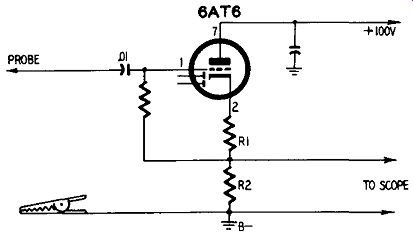
Fig. 1008. Circuit diagram of cathode-follower probe. The signal output
is taken from across R2.
We can carry this analogy a step further. The output transformer of an audio amplifier is a stepdown device. There is always less voltage on the output side (secondary) than there is across the primary. A cathode follower behaves in the same way. The output is always less than the input when using a cathode-follower probe.
The plate of the cathode follower is at r.f. ground potential.
This means that the signal currents appearing at the plate of the tube do not immediately flow through a load resistor (as in usual amplifier operation) but instead are bypassed to ground. From the ground point the signal currents flow back to the cathode of the tube. In doing so, this current, you will note, goes through two resistors. One of these (R1), is our cathode resistor and sup plies bias for the tube. The other resistor (R2), also located in the cathode circuit, is our load resistor and it is across this component that the output signal voltage is developed.
Using the cathode-follower probe
The probe is very useful in circuits where the signal level is sufficiently large enough to overcome the loss in the probe. It is rather difficult to give a strict rule about this since the sensitivity of your scope will also be a determining factor. The probe can be used for testing the output of high-impedance crystal phonograph pickups, video-amplifier circuits or any circuit where faithful reproduction of the signal on the scope is important.
Grid-leak detector probe
This type of probe has the advantage of extreme sensitivity. Unlike crystal and vacuum-tube diode types, the grid-leak detector probe amplifies the signal being tested.
The grid-leak detector probe (see Fig. 1009) can pick up the radio signal right at the antenna input of a receiver or will even give an indication of the amount of signal appearing across an ordinary piece of wire. A grid-leak detector operates as a sort of combined diode triode, with the control grid of the tube functioning simultaneously as the diode plate and also as the control grid for the triode. Hence, this probe supplies both detection (rectification of the signal) and amplification. Its chief disadvantage is that it overloads easily and distorts comparatively strong signals. The probe is ideal for use where you simply want to trace from the antenna of a receiver to the speaker and are not concerned with the quality of the signal.
The probe tube shown in Fig. 1009 is a miniature type 6AT6.
The tube is used as a triode. The diode plates are connected externally and, since they are not used in the circuit, are wired to the cathode. Component values are not critical and you can substitute other values if you wish. You will find that the probe has greatest sensitivity when using a high-value resistance in the grid circuit, such as the 15 -meg-ohm unit illustrated. The 50-µµf capacitor in the plate circuit bypasses any carrier signal that may appear at this point. A small amount of audio will be bypassed also, but not enough to be significant. The bypass capacitor in the plate circuit should be not much larger than 50 µuf since you may begin to get excessive loss of audio signal.
The audio voltage appears across the 220,000-ohm plate load resistor. You can connect the output of the probe through a .01-µf capacitor to a pair of phones or to an audio amplifier.
Using the grid-leak detector probe
The probe can be used almost anywhere in a radio receiver.
All you need do is go from input to output of each succeeding stage. For example, if you are tracing a signal through the i.f. stages, place the probe tip at the control grid of the i.f. tube and then at the plate of the same tube. If the signal appears at the control grid, but not at the plate, then the signal is being lost in that stage. If the signal strength at the plate is lower than that at the control grid, or if there is no apparent increase in signal strength, then the tube used in that stage may be weak or operating with incorrect potentials. Thus, the probe can be used to give you some indication of the relative gain of each stage.
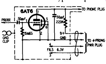
Fig. 1009. Grid-leak detector probe.
Such probes are extremely sensitive, overload easily.
If the receiver is dead, but all plus voltages seem to be normal, start at the antenna and trace the path of the signal through successive stages. The whole idea here is the same as in any other signal-tracing procedure. Narrow down the area of search until the trouble-giving component is located.
The grid-leak detector probe is sufficiently sensitive so that you can use it to trace hum. Locating a hum-causing component can sometimes be difficult and time consuming. This probe makes the job easier. Suppose, for example, that with your probe on the control grid of a tube the signal sounds clear and hum free, but that at the plate of the same tube the hum level rises seriously.
Substitute the tube and examine the components of that stage.
Use the probe to check Screen bypass capacitors. If your probe shows the presence of signal voltage at the screen of an r.f. amplifier or i.f. amplifier tube, the screen bypass capacitor may be open or the capacitance of the unit may not be large enough.
The probe will also help you find intermittents. Put the probe at the tube plate pin and tap the tube gently. If the signal changes or disappears, the tube can be suspected. With the probe at the same point, tap resistors and capacitors in that circuit. The signal should not be affected. Any component that causes the signal to fluctuate or disappear should be replaced.
Grid-dip probe
Few technicians recognize the close relationship between a grid dip meter and a v.t.v.m. Both instruments are useful. Often both are used on the same repair project-one to measure frequency, the other to measure voltage. The two instruments are physically similar. Each requires a relatively low B supply (about 150 volts), a sensitive d.c. meter and a probe. It seems wise therefore to combine them into a single unit with separate probes for each function. The same power supply and microammeter can be used for both.
Fig. 1010 shows a grid-dip probe made to plug into a home made v.t.v.m. The probe is housed in a 4 x 4 x 2-inch metal box into which a 7-lead cable can be plugged. The other end of the cable plugs into the voltmeter proper. When a.f. or r.f. voltage is to be measured, a voltmeter probe is substituted for the probe in Fig. 1010.
The grid-dip circuit shown in Fig. 1011 is simple and effective.
It consists of oscillating circuit L-C with a plug-in coil. Power for the 955 acorn tube is supplied through the cable. Since the tube oscillates at all times, grid current flows out of lead 2. This lead connects to the microammeter in the v.t.v.m. as shown in Fig. 1010. Outside and inside view of the grid-dip probe. The sides of the case are held in by self-tapping screws, are easily removed. No chassis is needed since the components can be mounted directly to the case.
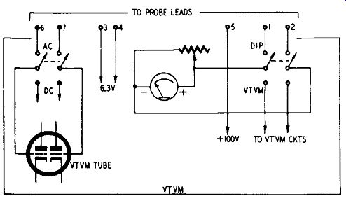
Fig. 1012. When the grid-dip probe is used, an auxiliary switch removes the
meter from the voltmeter circuits so it can measure the grid dip. A meter
shunt is also used. This adjusts the meter to full scale.
Using the probe
The probe is simple to use. First the meter is adjusted to full scale as mentioned. Then coil L is brought near an external circuit being measured. This may be a wavemeter, an r.f. amplifier tank, an antenna (through a coupling coil), etc. When the external tank resonates with L-C, power is absorbed from it. This causes a dip in the grid current. At maximum dip the unknown frequency is read from the grip-dip calibration.
Of course the grip-dip instrument is also an excellent signal generator. Simply couple L near an r.f. receiver and listen for zero-beat. Plenty of harmonics are available. This makes it easy to calibrate the grid-dip meter. At higher frequencies, a TV receiver helps a calibration.
Fig. 1013 shows a common type of voltmeter probe which can be used as companion to the grid-dip probe. The same lead numbers are used for the ground and filaments as in Fig. 1011. The other two, leads 6 and 7, connect to the v.t.v.m. tube grids.
Construction is straightforward, but two points need explanation. The bottom of an acorn tube extends below its socket.
Therefore the latter cannot mount directly on the metal box. Add a metal shelf ½ inch below the top of the box. It holds the sockets for coil L and the 955 tube. The shelf may be mounted either with spacers or brackets.
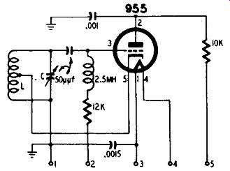
Fig. 1011. Circuit diagram of the grid-dip probe.

Fig. 1012. Wiring arrangement for connecting the grid dip probe to a sensitive
meter.
For high frequencies, a ¾-inch diameter polystyrene coil is convenient. Be careful in soldering to the pins. More often than not the heat softens the polystyrene and ruins the coil form. Try the following procedure: Saw the base off an Amphenol type 24 form (no prongs). This form fits neatly into a 4-prong miniature chassis plug (type 71-4S). The two are cemented together or they may be held together by screws. This makes a plug-in coil form with a bakelite base so there is no soldering problem. The chassis plug mates with Amphenol socket type 78-S4S.
Two coils are used with this probe. One has 8 turns occupying about ½ inch. This tunes over 10 and 15 meters. The other has 4 turns and oscillates on 6 meters. Other ranges may be deter mined experimentally; it is difficult to specify exactly at high frequencies.
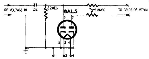
Fig. 1013. Probe for measuring r.f. voltage uses miniature 6AL5 duo-diode.
The grid-dip instrument tunes much more sharply than an absorption meter. A circuit does not have to oscillate to have its frequency measured by the grid-dip method. This offers a decided advantage. Not only must an absorption type meter depend upon an oscillator circuit to operate, but in the process a small amount of power is taken from_ that circuit. In cases of low-power high-Q circuits, noticeable impedance may be reflected.
-------------------------
Materials for probe
Resistors: 1-9,100, 1-12,000, ½ watt.
Capacitors: 1-50 µµf, mica; 1-1,000 µµf, mica; 1,500 µµf, ceramic; 1-50 µµf, variable.
Miscellaneous:
1-2.5-mh r.f. choke; 1-955 tube and socket; 1-4-prong socket (Amphenol 78-545); 2-coil forms (Amphenol type 24); 2-4-prong plugs (Amphenol 71-45); 1 -mhztal box 4 x 4 x 2 inches; 1-7-prong socket.
----------------
Probe housing
Crystal demodulator and voltage-divider probes are somewhat simpler in their physical construction than vacuum-tube probes.
Tube probes require some means for mounting and supporting the tube in the probe housing. In addition, the tube must also be supplied with filament and plate voltage. Miniature tubes are generally used.
The probe housing has a double purpose. It serves to shield the tube from stray fields, keeping hum and noise voltage out of the probe. Since a probe has to tolerate rough usage in servicing work, the probe housing also acts to protect the tube.
You can mount the probe tube in almost any kind of metal can. You can also use plastic or some type of insulated tubing.
This material will give protection, but you will lose the shielding effect. A small i.f. can, such as that shown in Fig. 1014, makes a fine probe housing. The tube that is used is a 1S5, although you can use almost any other type of miniature triode or pentode you may wish.
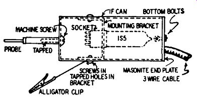
Fig. 1014. An i.f. transformer can makes a useful probe housing.
As shown in Fig. 1014, the tube is supported on a mounting bracket which holds the tube socket. The two ends of the bracket are bent at right angles. The bracket can be held in place by means of a pair of self-tapping screws. The probe tip will have to be insulated from the metal can. You can do this by inserting a prod tip in a small length of plastic rod. The other end of the rod is held to the metal can by a machine screw. You can make the required connection between the probe tube and the prod tip by running an insulated wire through one of the two holes at the top of the i.f. transformer can.
Naturally, you will have to make all of your connections before you put the tube and its mounting bracket inside the can. After you do so, place sponge rubber around the tube to minimize microphonics and to prevent damage to the tube from rough handling. Cut a piece of Masonite for the bottom end plate. This can be drilled so that it can be fastened to the open end of the i.f. can with the two mounting lugs already on the can. The cable can be held in place by wrapping a few turns of steel wire around it tightly and then looping one end over one of the lugs.
Portable signal tracer
The circuit for a complete signal tracer is shown in Fig. 1015. The probe uses a 1S5 m1mature pentode (triode-connected) which can be housed in an i.f. shield can in the same manner as that described in the preceding paragraphs. With the screen and the plate of the 1S5 tied together, the tube functions as a triode detector and amplifier. The 1S5 is suited for this job since it gives good pickup gain with little distortion. The circuit is simply that of a grid-leak detector and one stage of audio amplification. Few components are used and the entire audio section plus batteries can be put into a very small case.
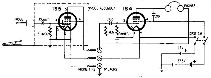
Fig. 1015. Completely self-contained signal-tracer and probe. The output
of the probe feeds into a single stage audio-amplifier. A midget output trans
former and speaker can be used instead of phones.
Using the tracer
Although the circuit is simple, you can get some surprising results. You can use it to locate weak stages anywhere from the antenna to the speaker of a receiver; find defective tubes, bad coupling capacitors, open coils ... and almost any condition you can name.
One of the tracer's biggest advantages is that no line isolation transformer is needed. Moreover, there is no bothersome inter action between the probe and the receiver. Fasten the alligator clip to the common negative or ground of any receiver and touch the control grid of the first r.f. stage or the antenna with the probe and a local station can easily be heard in the phones. Substitute a small output transformer and speaker for the phones, if you wish.
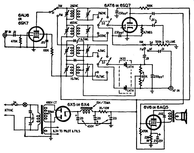
Fig. 1016. Circuit diagram of a tuned signal tracer that can be used for
servicing AM, FM, and TV receivers.
Always tune in a local or powerful station while checking the first r.f. stage because the r.f. energy here is very small. Now try placing the probe on the plate of the first r.f. amplifier (if the set has such a stage) and notice the volume. After this stage and through the rest of the receiver, the probe doesn't necessarily have to touch the soldered contacts but can be held close to the wire carrying the signal. When checking the last one or two audio stages, it is best to have the volume turned way down on the receiver, for the signal has been amplified quite a few times and is sometimes rather loud.
Signal tracer for AM, FM and TV
In an effort to achieve simplicity and a mm1mum of opera ting controls, many signal-tracing systems use a simple demodulator probe (either crystal or vacuum-tube diode) followed by a one-or two-stage audio amplifier. For most work such a tracing system is quite advantageous, but its usefulness is limited to moderately strong r.f. signals. An amplifying probe using a triode or pentode can be used instead, but such probes (like the more simple diode probes) have no selectivity and respond to all signals.
A tuned signal tracer has a number of factors in its favor.
Its sensitivity is much higher than other types of tracers and you have some control over the signal you want to examine. How ever, the tuned signal tracer is more complex than simple audio-amplifier tracers and requires somewhat more care in its construction. Fortunately, the probe used with the tuned tracer can be made as compact as you wish, is easy to construct.
The probe head for a tuned tracer can consist of a pair of 2.2-µµf ceramic capacitors in series. A short, low-capacitance coaxial cable should be connected between the probe and the signal tracer input circuit. For maximum versatility, you can also make up a complete set of probes for the tuned tracer, using crystals or tubes. The circuit of Fig. 1016 shows a grid-leak detector probe being used with the tuned signal tracer.

Fig. 1017. Photo of the vacuum-tube probe. The probe is very sensitive and
can be used in very low r.f. signal voltage stages.
You can use the tuned signal tracer shown in Fig. 1016 for tracing signals through the i.f. circuits of FM, AM and intercarrier type TV sets. The r.f. input terminal feeds into a pentode r.f. amplifier. SI in the plate circuit of this stage selects the primaries of the 262-and 455- khz AM i.f. transformers or the series-connected primaries of the 4.5-and 10.7 -mhz transformers. S2 selects either one of the AM i.f. transformers and connects the desired circuit to the AM detector using the diode section of the 6A T6. S3 selects the desired FM i.f. signal and feeds it to a discriminator using a 1N35 germanium duo-diode. S4 connects the volume control and the grid circuit of the 6A T6 triode to the AM or FM detector outputs or to the audio input terminal. The 6AQ5 is a conventional power-amplifier stage.
The constructor has a choice of using octal or miniature tubes. The latter type is recommended for compactness so the leads can be kept short.
Tube probe
A tube itself can be used as a probe, thus eliminating the need for mounting and supporting a tube inside a probe housing. A metal type 6K7, although used primarily for renewal purposes in older radio receivers, makes an excellent probe tube. The fact that the tube is practically obsolete for modern radio design work does not mean that it cannot be used as a probe.
A picture of the tube probe is shown in Fig. 1017. Start with a 6K7, a 6F5 or almost any other metal tube which has a grid cap on top. Cut a piece of ¼-inch copper tubing about 1/2 inch long. Solder it directly to the grid cap.
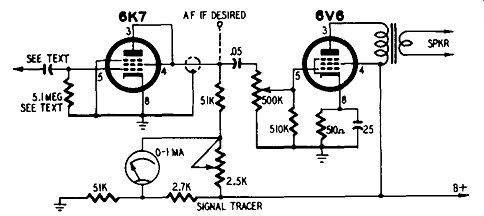
Fig. 1018. Circuit of the vacuum-tube probe. The 0-1 ma meter is a useful
feature, but can be omitted if desired.
The circuit diagram of the probe and an associated, simple audio stage is shown in Fig. 1018. The probe requires a small input capacitor and a grid leak. You will find it much more convenient to make these two radio components than to mount and support a typical capacitor and resistor.
To make the input coupling capacitor, take a piece of No. 10 copper wire about 1 ½ inches long. File one end to a point. Wrap the other end with a 1-inch strip of waxed paper, allowing the paper to overhang the end of the wire slightly. When enough
paper has been added for a tight fit, force the wrapped end of the wire into the copper tubing (previously soldered to the grid cap of the tube) and you will have your input capacitor.
Making the grid resistor is still easier. Using a knife, scrape the paint from the edge of the metal tube cover where it is crimped over the piece of bakelite at the top end of the tube. Now take a pencil and mark all over the bakelite, covering the entire surface between the metal edge of the top of the tube and the copper tubing connected to the grid cap. Rub the pencil graphite in well with your finger. Repeat the process once or twice, and you have formed the grid leak. If you do not care to use this type of resistor, you can always solder a small ½-watt resistor from the grid cap to the metal casing of the tube.
For convenience in changing tubes the probe tube is simply plugged into an 8-pronged female cable connector to which the lead-in cable is connected. The lead-in cable should contain a shielded plate lead, a ground wire ( or the shield can be used for this since it must also be grounded) and one filament lead.
The values shown in the meter bridge circuit should be closely followed. A 1-ma meter is preferred for sensitivity. Before use, the meter is adjusted to zero (while the probe tip is grounded) with the 2,500-ohm potentiometer. Thereafter, any input signal picked up by the probe will be indicated by the meter. If the signal contains audio components, they can be heard from the speaker.
The audio stage consists of a volume control, a 6V6 (or any other good output tube) and a 3-inch PM speaker.
In receiver trouble shooting, the ground clip on the probe is fastened to the receiver chassis. An input signal (such as a local station or an oscillator signal) can then be traced right from the antenna coil through each stage to wherever it stops.
Shield for tube probe when using the tube probe for work in very low signal level circuits such as the antenna input to a receiver, it may be necessary to have the volume control of the audio section set for fairly high gain. Under such circumstances, simply touching or holding the probe tube in your hand may produce hum, noise, or some sort of undesired signal pickup. You can avoid such situations by putting the tube probe in a shielded container.
One way of doing this is shown by the illustration, Fig. 1019.
The tube is mounted inside the shield and a wire is run from the control-grid cap of the tube to an input jack mounted at the top of the shield. The input jack can be of the type which will accommodate a needle point (such as used in test prods) or may be a short length of stiff wire or bus, force fitted into the jack. The grid capacitor and leak are mounted inside the shield can. The tube can be mounted in a socket and the wires of a cable connected to the socket pins or else you can use an octal type male-female connector assembly.
The outside metal shield should be connected to the shield pin of the tube. The shield pin is the number l pin on the socket. It is important to make this connection to get full shielding effect of the metal tube and the shield. The number 1 pin should be wired to the shield braid of the output cable and this in turn should connect to the chassis of the signal tracer unit.
If, in operation, the metal shield becomes warm, drill a few holes in it to allow for air circulation and dissipation of the heat.
Transformer or transformerless? A probe is a connecting link between the receiver on the bench and some piece of test equipment. In most instances, the ground side of the test instrument must be connected to the ground side of the :receiver being checked. Neglecting to do this will most often produce incorrect and unstable readings on your v.t.v.m. or scope.
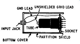
Fig. 1019. Method for shielding tube probe.
This requirement for having a common ground between receiver and test equipment is easily and readily done if the receiver and test equipment are both powered by transformer-type power supplies. However, many receivers, both AM and TV, are of the a.c.-d.c. or transformerless type. Such receivers may or may not have a hot chassis. The hot chassis types have one side connected to the power line. The possibility of having hot-chassis sets to work on makes a line-isolation transformer at the service bench essential, to avoid the possibility of shock, due to the operator touching the chassis while standing on a damp floor, touching a conduit, pipe, or other ground path.
Transformerless receivers should always be powered by a line isolation transformer. The auto-transformer type of unit is un suitable and will not isolate the receivers-separate primary and secondary windings must be provided.
Using a line-isolation transformer also protects the test equipment. Instrument cases are usually grounded to avoid minor shocks to the operator when he touches the metal portions of the equipment. Minor shocks result from the use of shunt capacitors in the line filters of the test instruments; these line-filter capacitors conduct a small current, sometimes sufficient to be felt by the operator. Hence it is common practice to ground the instrument cases.
Since the instrument cases are grounded, connecting the instruments to a hot-chassis circuit can result either in blown fuses, or in burned-out components in the instruments. The line-isolation transformer prevents such damage.
Rapid servicing with probes
For servicing rapidly with probes you must know just what each type of probe can do, and just where in a circuit you should apply a particular probe. This means that you must have an understanding of radio and TV circuits and, how they function. However, for speedy servicing you must also be able to identify quickly the various circuits exposed by the under side of a chassis.
The technician should learn to look for various "landmarks" as soon as the receiver chassis is placed on the bench. Some of these are the peaking coils in the video-detector circuit, which are suitable points for probe connection in i.f. alignment; and the mixer tube, a suitable point for capacitive injection of the sweep signal into the i.f. input circuit.
The a.g.c. bus, to which the d.c. returns are made from the grid circuits of the i.f. amplifier tubes, usually can be located without using a circuit diagram for the receiver. Most of the present-day tubes used in i.f. amplifiers have pin 1 as the control grid, and unless unfamiliar i.f. transformers are used in the receiver under test, it is easy to pick out the return point of the grid circuit, which identifies the a.g.c. bus. Fixed d.c. bias should be applied between the a.g.c. bus and chassis ground to stabilize i.f. amplifier operation during alignment and to set the gain at a suitable point.
Then the front end is of a familiar type, the local-oscillator tube can be quickly located. In the majority of cases, the technician will reach for a dummy oscillator-mixer tube which he has made up.
The output of the video amplifier is usually easy to locate, also; it consists of the final pair of peaking coils in the signal-circuit line-up, and the output from this set of coils is fed to either the grid (green lead) or to the cathode (yellow lead) of the picture tube. Although the video amplifier is not always checked during an alignment job, complaints of poor picture quality are some times traced to this section.
AMAZON multi-meters discounts AMAZON oscilloscope discounts