AMAZON multi-meters discounts AMAZON oscilloscope discounts
A voltage-doubler probe has considerable utility in television trouble-shooting procedures because it makes possible double the amount of deflection on a scope screen that can be obtained from a half-wave probe (assuming a symmetrical waveform in put such as a sine wave or square wave). Hence, it is useful in signal tracing low-level stages. On the other hand, a voltage doubling probe has considerably lower input impedance than a half-wave probe and its application is accordingly limited to medium- and low-impedance circuit testing. The voltage-doubling probe also has less frequency response than a half-wave probe and should not be used in circuits carrying frequencies higher than standard intermediate frequencies in TV receivers.

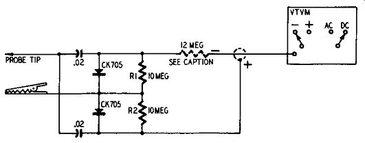
Fig. 301. Circuit diagram of voltage-doubler demodulator probe. This probe
uses a pair of matched crystal diodes.
When used out of its response stage, the voltage-doubler probe network goes into complex resonances which cause severe variations in the output voltage from the probe. At some frequencies the output may be practically zero while at other frequencies the output may be several times the voltage of the input. Consequently, the response of such a probe is unpredictable when used outside of its rated frequency range. The maximum allowable input voltage for a voltage-doubler probe is approximately the same as for the usual single crystal probe.
A typical voltage-doubler demodulator probe is shown in Fig. 301. While designed for work with a scope, it can also be used with a v.t.v.m. In operation, the carrier component of the modulated wave is rectified and filtered to a d.c. voltage, while the envelope which represents the modulating signal is passed by the probe network into the vertical amplifier of the scope.
Some of the· techniques used with the voltage -doubler probe are the same as those described in the preceding section. For example, if you want to calibrate a marker generator, mark a ratio-detector S-curve, etc., refer to Section 2 for full details.
Input voltage limitation

Fig. 302. Voltage-doubler probe designed for use with a v.t.v.m. The 12-meg-ohm
resistor is inserted when the probe is used with a v.t.v.m. having a 25 -meg-ohm
input resistance. Use a jumper here if the v.t.v.m. has an 11-meg-ohm input
resistance.
A voltage-doubler probe is also known as a peak-to-peak probe.
Unlike the half-wave type of probe described in Sections 1 and 2, the voltage-doubler probe can be used for the test and measurement of nonsymmetrical waveforms. In a TV set, these wave forms are found in the sync and sweep circuits. It is dangerous to use a crystal type voltage-doubler probe in sync and sweep circuits, since such voltages are much higher than the maximum rating of the crystal and will undoubtedly burn it out. It is true that there are a few test points where you can use the crystal voltage-doubler probe. For example, you can use it at the cathode of the sync separator tube or at the cathode of the horizontal control tube.
These are low-voltage, low-impedance points. However, even with manufacturers' literature at hand giving you the expected amount of peak-to-peak voltage, it is always possible to put the probe tip on the wrong pin of a tube.
Crystal probes of the half-wave and voltage-doubler types will not be damaged by application of voltages from r.f., i.f. or 4.5 -mhz circuits. For scope work in sync and sweep circuits it is advisable to use a vacuum-tube type peak-to-peak probe. These probes are described in Section 10.

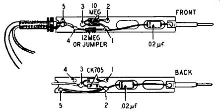
Fig. 303. Construction of a voltage-doubler probe. The parts are mounted on
a terminal board. Front and back views are shown. The numbers, I to 5 ir1clusive,
indicate connections made through brass soldering rivets.
Peak-to-peak probe for v.t.v.m.
Voltage-doubler probes are designed for use with a particular test instrument, such as a scope or a v.t.v.m. The circuit diagram in Fig. 302 shows a commercial type probe designed for use with a v.t.v.m. This probe can be used for peak-to-peak voltage measurements of complex TV waveforms. The probe has an operating frequency range of 5 khz to 5 mhz. The maximum input to the probe is 80 volts peak-to-peak and/or 600 volts d.c. The output of the probe is negative d.c. volts equal to the peak-to-peak voltage of any waveform, complex or sine.
Since the output of the probe of Fig. 302 is negative, the v.t.v.m. should be set to read negative d.c. volts. You can then read peak-to-peak volts directly on the d.c. scales of the v.t.v.m. without the need for using any multiplying factor. Because of the nonlinearity of the crystal diodes, voltages below 5 volts peak to-peak will give a lower-than-normal indication on the v.t.v.m.
If you will examine the circuit of Fig. 302 carefully, you will see that the shield braid of the output cable connects to one end of the crystal diode load resistor (bottom end of the 10 -meg-ohm resistor R2). The shield braid also connects to the negative (ground) side of your v.t.v.m. This means that, when using this probe, you should not ground your v.t.v.m., nor should you connect the ground lead of the v.t.v.m. to the chassis of the set being fixed as this will short one of the crystals and its load resistor.
The construction of the probe is shown in Fig. 303. The parts are mounted on a terminal board. The illustration shows how the components are placed on both sides of this board.
Calibration of marker generator
A voltage-doubler probe is very useful for calibrating a marker generator because the probe works out of a low-impedance source in this application. It will give double deflection on the scope screen as compared with the deflection obtained from a half-wave probe. Accordingly the operator can work farther out on the harmonics of a given crystal. Since the voltage of the harmonics is approximately inversely proportional to the order of the harmonic, the advantage of the doubler probe is that calibration can be carried out at twice as high a frequency as when a half-wave probe is used.
Marking ratio-detector S-curve
Like the half-wave crystal probe, the voltage-doubler probe will be found of great value in determination of the 4.5 -mhz point on an S-curve. The doubler probe has an advantage in this application. If the marker voltage is quite weak, the marker will appear double-height on the scope screen when the voltage-doubler probe is used.
I.f. signal tracing and sync-buzz tracing
A voltage-doubler probe can be used for i.f. signal and sync buzz tracing. When used for signal tracing, the TV receiver is energized at the antenna terminals by a suitably modulated r.f. signal, a sweep-frequency signal or a TV station signal. To trace this signal through the signal circuits of the receiver, the voltage doubler probe is applied progressively to the plate terminals of the mixer, first i.f., second i.f., third i.f. and fourth i.f. stages. It is preferable to test at the plate terminals of the i.f tubes instead of testing at the control grid terminals, because the grid circuit often has a higher impedance than the plate circuit.
Circuit loading and resulting circuit disturbance are lessened when the voltage-doubler probe is applied at the plate terminal of an i.f. tube. The voltage-doubler probe can be applied directly in 4.5 -mhz sound circuits to determine the percentage of down ward modulation produced by the 60-cycle buzz voltage; in this application a d.c. scope is required. The voltage-doubler probe must be used with a suitably tuned head to check for sync-buzz generation in the i.f. or video amplifiers, as will be explained later.
Color TV testing
The circuit diagram of a typical commercial peak-to-peak high frequency probe is shown in Fig. 304. Probes of this type can be used in making video-frequency sweep tests of the chroma band pass amplifier and other video-frequency circuits in color television receivers. In such applications, place the probe across a suitable low-impedance point (such as the color-intensity control) to avoid circuit disturbance by the capacitive component of the probe input impedance. The input capacitance of the probe shown in Fig. 304 is 5 µµf. This is sufficient to distort the response of the bandpass circuits if shunted across the filter inductors.

Fig. 304. Typical circuit of commercial peak-to-peak high frequency probe.
Signal source used in signal tracing
The pattern observed on the scope during signal-tracing procedures depends upon the type of signal applied to the antenna terminals of the receiver. In any case, the scope can be swept at 60 cycles per second. When a TV station signal is used as a signal source, the operator sees the composite video signal on the scope screen. (A reasonably strong signal must be used in order to obtain satisfactory scope deflection when testing early i.f. stages, or a scope preamplifier must be used.)
The relative height of the pattern from one i.f. stage to the next is a measure of the progressive gain of the receiver. When a sweep frequency generator is used to energize the antenna terminals of the receiver, a frequency response curve will be observed on the scope screen. The bandwidth of the response curve is normally greatest at the first stage in the receiver and least at the last stage in the receiver (unless circuit trouble exists).
Dead-stage indication, regeneration and sync buzz
When a dead i.f. stage is encountered in the receiver, no deflection is obtained on the scope screen. If the trouble is a weak stage, you will note a decrease, instead of an increase, in the height of the pattern. Regeneration in an i.f. stage causes an abnormal decrease in bandwidth and an abnormal increase in gain. The maximum normal gain of an i.f. stage (in the absence of regeneration) is approximately 15. Lesser gains are observed with appreciable grid bias on the i.f. amplifier tubes.
The voltage-doubler probe can also be used advantageously to check i.f. amplifier stages and video-amplifier stages for generation of 60-cycle sync buzz. To make a buzz check, a tuned head (parallel-resonant circuit) is tuned to the sound-carrier frequency and connected to the input terminals of the voltage-doubler probe. The tuned head is then coupled inductively to the i.f. coils or to the peaking coils of the receiver for test checks.
Peak-to-peak voltage measurements
The voltage-doubler probe responds to the peak-to-peak voltage of the signal under test, hence can be used to measure peak to-peak voltage values in combination with a d.c. v.t.v.m. Before undertaking to make such peak-to-peak voltage measurements, you should check the scale indication of your v.t.v.m. against a known source of peak-to-peak voltage in order to determine the attenuation factor of the probe. Since the input resistances of various v.t.v.m.'s are different and since the front-to-back ratios of various crystal diodes are also different, the voltage-doubler probes must be individually calibrated for insertion loss.
The voltage-doubler probe eliminates the basic error commonly encountered when the operator attempts to make a peak to-peak voltage measurement with a half-wave probe. A serious error usually arises in such cases because the half-wave probe must be "turned over" in making the required pair of measurements and very serious circuit loading results. Accordingly, a correct peak-to-peak voltage value is obtained when the voltage-doubler probe is used, but an incorrect peak-to-peak voltage value is obtained when the half-wave probe is used for such measurement.
Frequency response of probe
The frequency response of the voltage-doubler probe can be made essentially Hat up to 150 mhz: the probe is also useful for comparative measurements at still higher frequencies. The probe is therefore very useful in marker-generator or calibrating procedures, combining high sensitivity with good frequency response. In general, when a half-wave probe does not provide ample deflection on the scope screen, the voltage-doubler probe should be utilized.
Keep in mind, however, that a half-wave probe can provide additional flat frequency response up to 300 mhz.

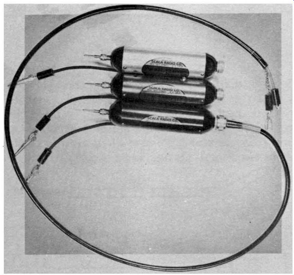
Fig. 305. Three types of scope probes used in TV test work. (Top) Crystal-demodulator
signal-tracing probe; (center) low-capacitance high-impedance 10-1 voltage-divider
probe; (bottom) 100-1 capacitance-divider high-voltage probe.
Sixty-cycle rejection of probe
Since the voltage-doubler probe utilizes shunt detectors in combination with relatively small series-charging capacitors, 60-cycle hum voltage is greatly attenuated with respect to r.f. or i.f. voltage.
Hence, tests in heater circuits, a.g.c. lines and d.c. supply lines are greatly facilitated. The operator can check for "hot" bypass or decoupling capacitors, heater "hash" or video voltage in a.g.c lines without encountering serious disturbance of the scope screen pat tern from hum or heater voltage.
Commercial type probes used in television servicing (and also for radio repair) are relatively inexpensive and present a professional appearance. ·whether you buy or build is simply a matter of personal choice. In Fig. 305 we have three different types of scope probes used in television test work. At the top is a crystal demodulator signal-tracing probe; at center, a low-capacitance high-impedance, 10-1 voltage-divider probe; at bottom, a 100-1 capacitance-divider high-voltage probe. The crystal demodulator signal-tracing probe has already been discussed. The other probes form the subject material for subsequent sections.
Commercial types of peak-to-peak probes use either crystals or vacuum-tube diodes. You will find a description of tube type voltage-doubler probes in Section 10.
(Note: This guide based on the 1955 book, Probes)
AMAZON multi-meters discounts AMAZON oscilloscope discounts