AMAZON multi-meters discounts AMAZON oscilloscope discounts
TV receiver circuits can develop high voltages which are beyond the voltage-handling capability of scope input circuits and which also exceed the voltage rating of simple attenuating probes.
For example, the plate of the horizontal output tube in a TV receiver may develop as much as 6,000 peak-to-peak volts. To inspect the waveshape of the voltage and to measure its peak to-peak value, a 100-to-1 probe is essential.
A representative 100-to-1 probe will have a high input impedance; its input capacitance will be about 1.25 µµf and its input resistance infinite. Such a probe will not noticeably load high voltage circuits in a receiver, and measured peak-to-peak voltages will be correct. This probe also has high-voltage insulation and will withstand 7,500 peak volts before gas currents develop which disturb the attenuation factor.
This type of probe is not frequency-compensated like conventional low-capacitance probes. The chief reason for this omission is that high-voltage tests are made in horizontal sweep circuits where the highest frequency involved is only about the 10th harmonic of 15,750 cycles.
The probe should be calibrated and adjusted for a 100-to-1 attenuation factor when used with a particular scope. When the probe is used with other scopes, the calibration factor may be slightly in error. The probe should be of shielded construction to avoid stray field pickup which would distort the display.
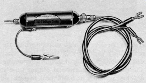
Fig. 601. Photo of a high-voltage, capacitance-divider probe.
A commercial 100-to-1 high-voltage, capacitance-divider probe is shown in Fig. 601. The head is made of special insulating material to withstand severe potentials in TV high-voltage supply networks. In Fig. 602 we have the 100-to-1, capacitance-divider probe being used in the high-voltage cage of a TV receiver.
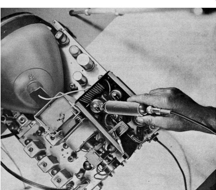
Fig. 602. Photo shows capacitance-divider probe being used to check high voltage·waveforms.
Probe design
The various capacitances of a high-voltage divider probe are shown in Fig. 603. C1 is a high-voltage capacitor or a tube acting as a capacitor. Trimmer capacitor C2 is adjusted for a 100-to-1 voltage ratio with a given cable and scope.
The input impedance of a high-voltage, capacitance-divider probe is made as high as possible and depends, of course, on the frequency. In order to withstand the high voltages encountered in TV test work, the first capacitor (C1) in the probe network can be a high-voltage rectifier tube, such as a 1x2-A. The plate to-filament capacitance of these tubes ranges from 0.85 to 1.5 µµf. Thus, the input impedance of the probe at the fundamental frequency of the flyback pulse (15,750 cycles) is approximately 6 megohms and approximately 0.6 megohm at the 10th harmonic.
Since the probe impedance (even at the 10th harmonic) is still much higher than the internal impedance of the circuit under test, the flyback pulse is reproduced essentially without distortion.
The circuit of a 100-to-1 probe is shown in Fig. 604.

Fig. 603. Circuit of a high-voltage capacitance-divider probe. C1 can be the
plate-filament capacitance of a 1x2-A high-voltage rectifier. Trimmer capacitor
C2 is adjusted for a 100-to-1 voltage ratio with a given cable and scope.
In addition to being able to withstand applied voltages up to 12 or 15 kv, this capacitor must have a physical shape that will not encourage corona discharge in the probe head.
A trimmer capacitor (C2) is provided so that the capacitance ratio C2/C1 can be adjusted to exactly 100-to-1. This attenuation factor makes it easy to measure peak-to-peak voltages. Once the scope has been calibrated for a given peak-to-peak deflection sensitivity, it is necessary only to multiply the scope reading by 100. The calibrating trimmer capacitor is mounted in the probe head and does not have to be a high-voltage type with a 100 to-1 ratio the calibrating capacitor need withstand only I% of the signal voltage applied to the probe tip. The highest a.c. voltage likely to be encountered in TV work is about 15,000, so that the trimmer capacitor need withstand only 150 volts.
Commercial probes are shielded to avoid hand-capacitance effects and stray-field pickup that may confuse the scope trace.
Since the probe is calibrated for a given shielded-cable capacitance, the calibrating capacitor C2 must be readjusted if the probe is used with different cables and scopes.
Probe construction

Fig. 604. Practical circuit arrangement of a high-voltage capacitance-divider
probe.
For TV servicing, two high-voltage probes are needed. One of these, the resistive type, is used only for the measurement of high d.c. voltages. (It is described later in this section.) The other high-voltage probe, often called the 100-to-1 divider probe, is for testing high-voltage pulses.
When constructing a probe of the latter type, both the cable and input capacitance of the scope must be considered, since
these form part ·of the capacitance-divider network. For an attenuation of 100-to-1, C2 must be adjusted so that
C2 + C_B. + C_C. = 99C1
A design for building your own capacitive type high-voltage probe is shown in Fig. 605. If you wish, you can solder a probe pin to the plate cap of the 1x2-A. This will help in testing in crowded spots. The 1 X2-A is not actually used as a tube, but rather as a capacitor, taking advantage of the -interelectrode capacitance between filament and plate. The tube has a rating of 18,000 volts maximum, this being far in excess of normal pulse voltages found in TV sets. The 1X2-A corresponds to C1 in Fig. 603.
To build the unit, connect either of the filament pins of the tube to one terminal of a ceramic trimmer capacitor having a range of 7-45 µµf. It isn't necessary to use a tube socket since you can solder directly to the filament pin. Now strip one end of a 2-foot length of coaxial cable, such as RG59U. Connect the center lead of the cable to the terminal on the trimmer that is connected to the filament pin of the 1 X2-A. The shield braid of the cable should be wired to the other side of the trimmer. Cover the tube with Scotch tape and coat the tape with coil dope or Duco cement.
Before the cement or dope has dried, insert the assembly into polystyrene (plastic) tubing. The cement will form a strong bond between the inside of the plastic tubing and the 1X2-A. Drill a hole in the plastic tubing so that it faces the adjustment screw of the ceramic trimmer. The hole should be large enough to pass a small screwdriver or an alignment tool.
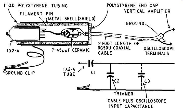
Fig. 605. Design for building your own high-voltage capacitance-divider probe.
The 1X2-A corresponds to C1 in the circuit diagram.
At this stage, the job is almost done. Cut out a small circular piece of plastic having a diameter of 1 inch. Drill a hole in the center to allow clearance of the coaxial cable. Now place a metal shell over the probe unit. Run a connecting wire from the shield braid of the coaxial cable to the metal shell. If the shell is made of copper, you will be able to solder directly to it. If the shell is aluminum, you will have quite a bit of difficulty in making a soldered connection. Instead, drill a hole and mount a soldering terminal, using a 6-32 machine screw. A ground clip must also be attached, as shown in the illustration. The circular end cap, previously prepared, can now be fastened in place with Duco cement or coil dope.
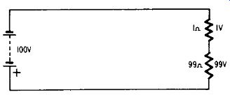
Fig. 606. Simple resistive network illustrates probe action.
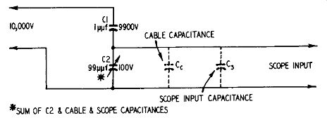
Fig. 607. Circuit showing voltage divider action of probe.
How the probe works
To understand how the probe operates, first consider the simple resistive network shown in Fig. 606. Here we have two resistors in series placed across a 100-volt source. The voltage drops across each resistor will be determined by the amount of resistance.
The total resistance in the circuit is 100 ohms and consists of two series resistors, 1 ohm and 99 ohms. The voltage (100) of the source distributes itself proportionately between the two resistors. Thus, we have I volt across the 1-ohm resistor and 99 volts across the 99-ohm resistor.
Now examine Fig. 607. The only difference between the circuit in Fig. 607 and that of the previous illustration is that in one instance we have series resistors and in the other series capacitors.
The voltage-divider action, however, is the same in both cases.
In Fig. 607, C1 represents the interelectrode capacitance of our 1X2-A. The tube manual quotes this capacitance as being 1 µµf.
In series with this we have our trimmer capacitor (C2). Shunting the trimmer is the capacitance (C1) of the coaxial cable plus the input capacitance (C.) of the scope. Trimmer C2 must be adjusted so that the total capacitance (C2 plus cable capacitance plus the scope input capacitance) is 99 µµF. This is best illustrated by the simple network of Fig. 608.
Capacitors C1 and C2 will now act as a voltage divider for a.c. pulses in the same way in which the resistors acted as a voltage divider for d.c. There is one important difference however. The reactance of a capacitor, expressed in ohms, is inversely proportional to its capacitance. All this means is that C1 will have 99 times as much reactance, in ohms, as C2. If we put this net work across a source of 10,000 volts, then we will get a 9,900-volt drop across C1 and a 100-volt drop across C2, as shown in Fig. 607.
However, C2 is right at the input to our scope. This means that whatever voltage we measure on the screen of the scope must be multiplied by 100 to give us a true estimate of it.
Which divider probe?

Fig. 608. Arrangement of various capacitances in the probe.
A 100-to-1 high-voltage, capacitance-divider can give much more accurate results than a 10-to-1 capacitance-divider probe in many circuits where the technician ordinarily uses a 10-to-1 type. It is much better, for example, for checking the waveform and peak-to-peak voltage at the plate of the damper tube or at the plate of the horizontal oscillator. The input impedance of the 100-to-1 probe is higher than the input impedance of the 10-to-1 probe. Hence, it imposes less loading on the circuit. On the other hand, it may be impossible to get usable vertical deflection in low-level circuits with the 100-to-1 probe.
Most typical service scopes have a vertical deflection sensitivity of approximately .02 volt r.m.s. per inch at full gain, corresponding to a sensitivity of .057 volt peak-to-peak per inch. (Sine wave r.m.s. X 2.83 = peak-to-peak voltage; .02 X 2.83 = .0566 or .057 approximately.) Under these conditions the 100-to-1 probe will provide 1 inch of deflection with an input signal of 5.7 volts peak-to-peak. If the signal voltage is less than this, the 10-to-1 probe will probably have to be used.
Although it is possible to provide an individual shielded output cable for each probe, the present trend is to provide a single universal shielded input cable which may be used with any one of an entire kit of probes.
How to check probe attenuation factor
Most TV service scopes are provided with a decimal step attenuator. To check the calibration factor of the capacitance- divider, high-voltage probe, the scope is first applied across a low-impedance circuit such as the cathode of the damper tube, using direct leads. The step attenuator is set to the Xl position and the vernier attenuator is adjusted for any convenient number of squares of deflection on the screen. The probe is then connected to the scope and the step attenuator advanced to the X100 position. If the attenuation factor of the probe is correct, the waveform will then occupy the same number of squares on the scope screen as before. If it does not occupy the same number of squares, it can be adjusted by varying the trimmer capacitor.
The shaft trimmer should be slotted to permit screwdriver adjustment.
Use of 100-to-1 probe with miscellaneous cables
Like the 10-to-1 probe, the 100-to-1 probe cannot be properly used with any cable other than the standard cable supplied with the probe. The reason for this precaution is that the attenuation factor of the probe depends to a large extent upon the capacitance of the connecting cable. Miscellaneous cables will not have the required value of capacitance. If it is desired to use a cable other than that supplied, the service technician should check the attenuation factor of the probe by the method outlined in the fore going paragraph.
Use of probe with uncompensated scope
Some service scopes do not have a compensated input system.
The input capacitance of such a scope will vary as the attenuator is varied, hence the calibration factor of the 100-to-1 probe will be changed somewhat. Further, it is very likely that waveform distortion will be encountered at the lower settings of such an attenuator due to frequency discrimination and phase shift in the attenuator itself. For these reasons, the use of the 100-to-1 probe with an uncompensated scope is not recommended.
Behavior of probe in 60-cycle circuits At 60 cycles the 100-to-1 probe will not have a correct attenuation factor and waveforms will be severely distorted. At 60 cycles the capacitance of the probe head is effectively working into a constant resistance. The reactance of the probe head is not constant, but inversely proportional to frequency. In consequence, each harmonic component of the waveform undergoes a different attenuation. As an example of this limitation, application of the probe is restricted to the horizontal sweep circuits.
This is not a serious limitation since high a.c. voltages (beyond the capability of the 10-to-I probe) are encountered only in the horizontal circuits. The 10-to-I probe (See Section 5) is adequate to accommodate the operating voltages encountered in vertical sweep circuits.
Using the high-voltage probe
When alternate light- and dark-gray vertical bars appear at the left side of the raster, it may be difficult to tell at a glance whether this effect results from ripple in the high-voltage supply or from some other cause. But with a high-voltage, capacitance-divider probe the technician can see the high-voltage ripple on his scope screen and measure its peak-to-peak voltage. He is then in a position to discuss matters in practical terms.
Similarly, when there are slight but rapid fluctuations in picture brightness, you may suspect intermittent leakage in a high-voltage filter capacitor. Of course, a substitution test will answer the question, but you can save time and trouble with a capacitance divider probe and scope. In the case of an intermittent leak in a high-voltage filter capacitor, the a.c. ripple across the capacitor will jump substantially during the brightness fluctuations. This test is more accurate than using a v.t.v.m. and high-voltage d.c. probe, because the pointer response of a v.t.v.m. is very sluggish compared with the inertialess response of the electron beam in the cathode-ray tube. These rapid voltage variations are almost completely smoothed out by the mechanical inertia of the meter movement in the v.t.v.m., but they are reproduced faithfully on the scope screen when you use a capacitance-divider probe.
A high-voltage, capacitance-divider probe is almost an absolute necessity for checking the shape and peak-to-peak value of the voltage waveform at the plate of the horizontal output tube.
This is a key test point in cases of sweep-circuit trouble, and the alert technician usually starts his trouble shooting here. We can not hook the scope directly to the plate of the horizontal output tube. The high a.c. voltage at this point would promptly burn out the scope input circuit; the blocking capacitor in the average scope is rated at only 600 volts.
We cannot use a low-capacitance 10-to-I probe at the plate of the horizontal output tube because the 6,000 to 7,500 volts peak- to-peak at this point would invariably flash across the probe network, which is not rated for this type of testing. Some technicians make a practice of using a gimmick for this purpose or merely holding the tip of a 10-to-1 low-capacitance probe near the insulated lead to the plate of the horizontal output tube. Although these expedients will show the a.c.-voltage waveform on the scope screen, they are worthless for checking peak-to-peak voltage. And in most cases we must know the exact value of this voltage to get a true picture of conditions in the circuit.
Another highly questionable expedient in making these tests is to use a high-voltage d.c. probe (actually intended for use with a v.t.v.m.) with the scope. This is even less satisfactory than a 10-to-1 low capacitance probe, because the unshielded multi plier resistor in the high-voltage d.c. probe is highly susceptible to hand-capacitance effects and 60-cycle stray fields. Besides, the scope pattern changes with the slightest movement of the probe.
The only satisfactory and safe method of working with these high voltages is to use a properly designed, high-voltage, 100-to-1 probe.
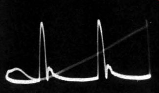
Fig. 609. Normal sweep waveform at the plate of horizontal-output tube, sun
with the aid of a 100-to-1 capacitance-divider probe. Diagonal line is scope
re-trace. Peaks are about 6,000 volts high.
Spotting flyback defects
A typical normal waveform at the plate of the horizontal output tube is shown in Fig. 609. The shape of the wave helps the technician identify certain defects in the flyback transformer, and the peak-to-peak voltage shows the condition of the drive circuit.
For example, a large negative undershoot in the waveform (Fig. 610) indicates excessive reactance between the primary and secondary windings of the transformer. This undershoot may cause Barkhausen oscillations, which show up as one or two vertical black lines at the left side of the picture.
If the transformer has other defects, the undershoot may be followed by a large voltage ripple. This will modulate the intensity of the beam in the picture tube, especially if the receiver has no high-voltage filter network. This form of intensity modulation appears as a series of light- and dark-gray vertical bars starting at the left side of the raster and becoming weaker toward the center. The same screen symptoms can arise also from several other causes, so the scope check of the horizontal output waveform saves valuable time by eliminating certain sources of trouble.
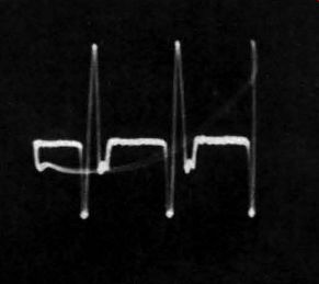
Fig. 610. Negative pulse in sweep-output waveform indicates excessive leakage
reactance in flyback transformer, may also generate Barkhausen oscillations.
Checking high-voltage circuits
High voltage can do harm in these ways: It may overload the scope amplifier and distort the displayed waveform, without doing actual physical damage to the scope. It may puncture blocking capacitors and char or burn out attenuator resistors. It may arc through insulating washers and carbonize terminal strips.
The plate of the horizontal output tube represents a typical circuit point that is potentially dangerous to the scope input system.
Ripple in output of high-voltage supply The 100-to-1 probe can be used for measurement of the peak to-peak voltage in the ripple waveform of the d.c. high-voltage supply output, provided a high-voltage filter capacitor is connected in series with the probe to block the d.c. voltage component, as shown in Fig. 611. This test procedure is very useful when tracing 60-cycle tunable buzz which varies in intensity with the setting of the brightness control. To eliminate high-voltage buzz, additional filtering should be used from the second anode of the picture tube to ground, or better shielding should be provided for the audio section of the receiver. In a test of this type, the operator must clearly distinguish between the display seen when the scope is set on 60-cycle sweep and that seen on 15.75- khz sweep. The ripple from the power supply is the display obtained on 15.75- khz sweep. The buzz voltage is the display obtained on 60-cycle sweep.
Many TV receiver circuits carry mixed waveforms of this nature and trouble shooting can be extremely puzzling to the beginner for this reason. As another example in point, consider the display of the horizontal sync pulse as obtained at the control grid of the picture tube. Two horizontal bars are seen in the background at the blanking level and at the maximum super-sync level, plus vague and less well defined tracery. This interference in the display is caused by the fact that the vertical sync and equalizing pulses are mixed with the horizontal sync pulse. It is interesting to note that a phasable 60-cycle blanking voltage can be utilized to obtain a clean display in such cases by blanking out the interference component. Detailed consideration of such matters, however, is beyond the scope of this guide.
High-voltage buzz
Experienced technicians have found many additional uses for the high-voltage, capacitance-divider probe. One of these uses is checking the output of the high-voltage filter system for regulation buzz. This should not be confused with sync buzz. Regulation buzz is caused by the limited current output capability of most flyback. and pulse-operated high-voltage systems-especially those that have voltage-doubler circuits. Since the picture-tube beam current is cut off for approximately 1,100 µsec (60 times a second) by the vertical blanking pulse, it follows that the output voltage from the unloaded high-voltage supply will rise several hundred volts for the duration of the blanking pulse and will then drop several hundred volts when the pulse ends and un blanks the screen. If the audio circuits and picture tube are adequately shielded, and if there are no serious faults in the audio system or FM sound detector, this regulation buzz is ordinarily below the threshold of audibility.
Behavior of probe in high-voltage rectifier section
The 100-to-1 probe is not suitable for use at the plate of the high voltage rectifier tube because gas currents will develop in the probe head which will impair the calibration factor of the probe and may also cause damage to the scope input circuit. To test the high-voltage rectifier, use a high-voltage d.c. probe (described later in this section) and measure the d.c. voltage output at the filament of the tube.
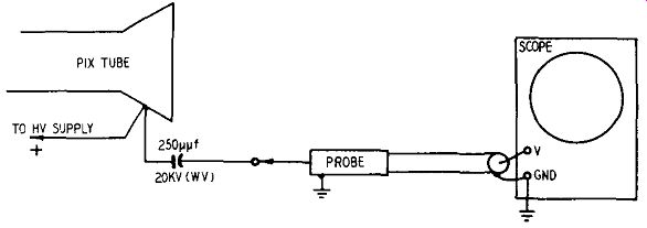
Fig. 611. Use of probe with high-voltage capacitor to block d.c. voltage.
Sweep circuits
The high-voltage, capacitance-divider probe is very useful for trouble shooting horizontal sweep circuits. It can be applied, for example, at the plate of the horizontal output tube or at the plate of the damper tube to check the operating waveforms and to measure their peak-to-peak voltages without impairing the waveshape or incurring danger of damage to the scope.
When used in these applications the scope should first be calibrated for a known sensitivity in peak-to-peak volts per square.
The probe is then connected to the scope and the calibrating factor is multiplied by 100. For example, if the scope has been calibrated for a sensitivity of 10 peak-to-peak volts per square, the probe converts this calibrating factor to 1,000 peak-to-peak volts per square and a 6,000-peak-to-peak-volt waveform will occupy 6 squares on the scope screen.
The operator should note that the peak-to-peak voltages of such waveforms are specified in the service notes for the receiver with a tolerance of 20%. This means that the receiver operation is judged to be faulty if a 6,000-peak-to-peak-volt wave measures more than 7,200 or less than 4,800 peak-to-peak volts. It must be observed in this regard that variations in power-line voltage are reflected through the receiver circuits as variations in measured peak-to-peak voltages. Receiver manufacturers specify wave form voltages upon the basis of a design center line of 117 r.m.s. volts.
Sync circuits
A TV station signal is almost always used in tracing sync circuit troubles, except in some very difficult cases where no signal at all can get through. The low-capacitance, high-impedance, 10-to-1 voltage-divider probe is the most useful type for working in these circuits since it is least likely to disturb circuit conditions through its loading effect.
Waveforms in sync and sweep circuits are characterized not only by their shapes, but also by their peak-to-peak amplitudes.
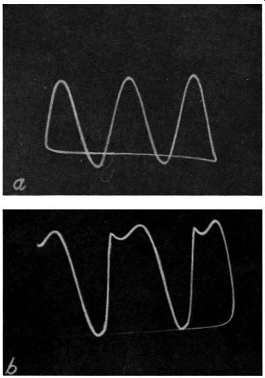
Fig. 612-a,-b. (a) Normal oscillator wave form in a Synchrolock-type horizontal
sweep circuit. (b) Distorted waveform indicates circuit defects. For maximum
accuracy in identifying circuit troubles, waveforms in this section of a TV
receiver should always be picked off with a capacitance divider probe.
Both these characteristics are generally given by the manufacturer in the service data for the receiver. Look for trouble in any circuit where the measured voltage is more than 20% off the specified value.
Of course, even if the peak-to-peak voltage is correct, wave form distortion as shown in Fig. 612 and Fig. 613 indicates trouble.
Obviously, this type of trouble shooting· cannot be done properly unless the technician has the necessary reference data as well as the right probe at hand. Fig. 612-a shows the normal oscillator waveform in a Synchrolock type horizontal sweep circuit. The distorted wave in Fig. 612-b indicates circuit defects. For maximum accuracy in identifying circuit troubles, waveforms in this section of a TV receiver should always be picked off with a low capacitance probe.
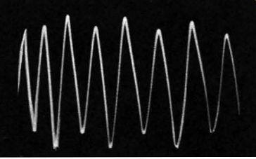
Fig. 613. The voltage of successive peaks is not the same. This symptom is
caused by the presence of a spurious low-frequency voltage in the circuit under
test.
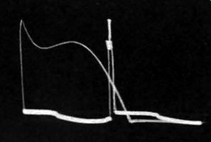
Fig. 614. Normal 6-kv flyback pulse at plate of horizontal-output amplifier.
The capacitance-divider probe attenuates the pulse by a factor of 100 to 1
to avoid-damaging the scope input circuit.
In the sweep and high-voltage circuits the receiver generally supplies its own signal for test. This may not always be true, especially in some types of horizontal-sweep circuits. For example, where the horizontal oscillator gets its plate voltage from the B plus boost line, it may be a question of "which came first--the chicken or the egg?" If the oscillator fails, there will be no B plus boost; if the B plus boost circuit fails , the oscillator won' t work. In these cases you can save yourself lots of time and aggravation with an auxiliary power supply.
We have deliberately re-introduced at this point, the subject of the 10-to-1 divider probe (previously discussed in Section 5) to emphasize the need for two probes when working in the sweep section. One of these should be a 10-to-1 probe and the other, a 100-to-1. Some horizontal sweep voltages are high enough to damage the scope input circuit unless a high-voltage capacitance divider probe is used. If you make a mistake and use a crystal probe or a low-capacitance probe at this point, you can say goodbye to the probe and the scope input circuit. A breakdown here may even burn out the flyback.
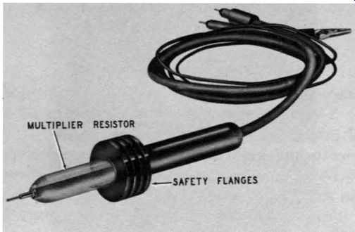
Fig. 615. Photo of typical high-voltage probe. Safety flanges present a long
barrier to high voltage.
A typical high-voltage waveform is shown in Fig. 614. Like the sync and other sweep waveforms, these kickback waves should have the shapes and peak-to-peak amplitudes specified by the manufacturer.
Grounding requirements are less severe with low-capacitance, 10-to-1 probes-in fact, with this type of probe the ground connection may sometimes be omitted-but a high-voltage probe must always be grounded! Unless the ground lead on the probe is clipped to the receiver chassis or B minus line, the whole test system will be hot and you may get a severe and possibly dangerous shock. Remember, even before step-up in the flyback trans former, there is a 3,000- to 6,000-volt pulse· at the plate of the horizontal output tube.
Throughout this text we have pointed out the importance of grounds and the precautions necessary when working with high-voltage horizontal circuits. We wish to stress that the lower B plus voltages are equally or even more dangerous. Shock from B plus or from line voltages can prove fatal.
High-voltage multiplier probe
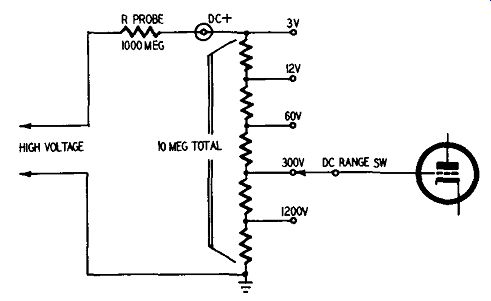
Fig. 616. The high-voltage probe becomes part of the voltage divider network
at the input to the v.t.v.m.
When you speak of high voltage in a TV receiver you can mean either pulse type voltages of the kind that appear at the plate cap of a horizontal output tube or you may refer to the d.c. voltage appearing at the second anode of the picture tube.
We have already seen how high pulse voltages can be measured.
To test high d.c. potentials, up to about 30,000 volts, a special high-voltage multiplier probe is needed. Circuit-wise, the probe resembles the isolation probe (described in Section 7). All that it contains is a resistor which acts as a voltage divider. However, the simplicity of its circuit does not give a clue to the physical construction of the probe. A photo of this giant of the probe family is shown in Fig. 615.
The resistor (or resistors in series) in a high-voltage probe are especially constructed to eliminate or minimize the possibility of voltage breakdown. These resistors are usually spiral-wound of metallic or carbon-film ribbon and are encased in a plastic having a high dielectric. They quite often have values as high as several hundred megohms and are manufactured to withstand the effects of changes in temperature and humidity.
The high-voltage probe can be considered as a true voltage divider, in the same classification as other voltage-divider probes.
In Fig. 616 we see how the resistance in the high-voltage probe is in series with the resistive input network of a v.t.v.m. Assume, for example, that the resistance in the high-voltage probe is 99 times that of the divider network. Assume also that we are measuring 1,000 volts. Of this, 990 volts will appear across the resistor in the high-voltage probe and 10 volts will be across the voltage-divider network in the v.t.v.m. You will now have a d.c. scale reading on the v.t.v.m. of 10 volts. This, multiplied by 100, will tell you the correct amount of d.c. voltage at the point of test.
Multiplication factor of probe
Resistive-type high-voltage probes are identified by their multi plying factor. Thus, a particular commercial probe might have a multiplying factor of 30. This means that when using such a probe the d.c. volts scale on the v.t.v.m. must be multiplied by this amount. For example, if you have the high-voltage test prod touching the filament of the high-voltage rectifier tube (a high-voltage point) and your v.t.v.m. reads 500 when set on the 1000-volt scale, then the high d.c. voltage output of your TV receiver is 15,000 volts (30 X 500 = 15,000). The amount of multiplication will depend upon the value of the multiplier resistor in the probe head and also upon the test instrument itself. Values of probe multiplier resistors vary from 480 megohms to as much as 1,320 megohms or more. Many manufacturers supply high-voltage probes designed for their particular instruments. When you buy this type of probe, make sure you get one that will give correct results when used with your test equipment. Not all probes have the same multiplication factor. This varies from as low as 15 to as high as 100. The most common types used in TV repair work have multiplication factors of 10, 15, 30 and 100. Calculating probe resistance If you have a v.t.v.m. or a sensitive instrument such as a 20,000 ohms-per-volt (or higher) multitester, you can easily calculate the amount of resistance that should be in the high-voltage probe.
Before you start, however, there are a few things you should know.
You must first decide what multiplying factor you want and you also need to know the input resistance of your particular v.t.v.m.
The input resistance of a v.t.v.m. usually includes the value of resistance in the isolation probe. For example, if a certain v.t.v.m. is said to have an input resistance of 11 megohms, 1 megohm is in the isolation probe used with that v.t.v.m. and 10 megohms is in the resistance divider input of the instrument itself.
To find the value of a high-voltage probe resistance, use this very simple formula:
R_probe = M (Rinput) - (Rinput - Rcable)
R_probe:
This is what we are looking for. It represents the amount of resistance in the high-voltage probe.
M:
This is the multiplying factor. If you want to have a probe such that you will multiply your v.t.v.m. meter scale by 10, then Mis 10. Similarly, if you want a multiplication factor of 100, then M is 100.
R_input:
This is the input resistance of your instrument. If you have a v.t.v.m., this information can be supplied by the manufacturer. The input resistance of a v.t.v.m. includes the resistance of the isolation probe used with it. If you have a 20,000-ohms-per-volt meter, you can calculate the input resistance by multiplying the full-scale reading of the meter in volts by its ohms-per-volt value. For example, if you intend using your 20,000-ohms-per-volt meter on the 1000-volt scale, then its input resistance is 20,000 X 1000 or 20,000,000 ohms (20 megohms).
R_cable:
This is the value of resistance in the isolation probe.
Suppose now that we had a multitester with a sensitivity of 20,000 ohms per volt and we wanted to buy or build a high voltage probe. Suppose also that our instrument had a 5,000-volt scale and that we wanted to have a multiplying factor of 10 so that we could use this scale to read up to 50,000 volts.
Rprobe = M (Rinput) - (Rinput - Rcable)
R probe = 10 (5,000 X 20,000) - (5,000 X 20,000-0)
R probe = 900,000,000 ohms or 900 megohms
In this particular illustrative problem we did not have to consider the resistance of the isolation probe since we calculated the input resistance of the test instrument without it. Note also that our probe is properly calculated only for use with the 5,000-volt scale of the meter.
We can use the same technique for working out a problem involving a v.t.v.m. Assume that we have a v.t.v.m. with an input resistance of 10 megohms and that we have an isolating resistor in the d.c. probe of 1 megohm. We want a scale factor of 100 times so that we can use the high-voltage probe to read 30,000 volts on the 300-volt scale of the v.t.v.m.
Rprobe = M (R_input) - (Rinput - Rcable)
Rprobe = 100 ( 1 1000,000) - (11,000,000 - 1,000,000)
Rprobe = 1,090,000,000 ohms or 1,090 megohms
If we had ignored the 1-meg-ohm resistance of the isolation probe, our answer would have come out to 1,089 megohms. This would have been close enough for us to identify the kind of probe to buy.
Note the difference between a high-voltage probe when used with a multimeter (such as a 20,000-ohms-per-volt meter) and a v.t.v.m. The input resistance of a multimeter (volt-ohm-milliammeter) depends upon which voltage scale you use. This means that your high-voltage probe can be used with only one scale of the multimeter. You must decide, before you build or buy the probe, just which scale you intend using. The input resistance of a v.t.v.m., however, is the same for all scales, hence you can set the v.t.v.m. multiplier switch to any desired position.
Using the high-voltage multiplier probe There are only a few places in a TV set where such a probe can be used, yet these are of such importance and such frequent causes of TV failure that having such a probe is convenient and necessary.
Modern television power supplies for picture tubes are characterized by high voltage, low current. The current produced by such high-voltage supplies is actually the scanning-beam cur rent of the picture tube and is usually less than I ma. The high voltage, low-current feature of such supplies means that they are high-impedance points and as such must be measured by high impedance test equipment. Measuring a voltage is equivalent to putting the test instrument in parallel with the circuit under test. In order not to disturb the circuit being measured, the testing device must draw a minimum amount of current from the circuit.
High-voltage multiplier probes are used in conjunction with v.t.v.m.'s or multitesters having a sensitivity of 20,000 or more ohms per volt. Most v.t.v.m.'s can read up to 1,000 volts d.c., a range that can easily be extended with high-voltage multiplier probes. These probes cannot be used with ordinary 1,000-ohms per-volt multitesters since such instruments require I ma for full-scale deflection, an amount of current that would seriously overload TV high-voltage supply circuits.
To use the probe, connect the probe cable to the v.t.v.m., setting the instrument on the desired high-voltage d.c. scale. Connect the negative lead of the v.t.v.m. and also the ground lead of the probe to the TV chassis. When working with a transformer less type TV set, use an isolation transformer, or else make sure that neither the exposed TV chassis nor the test instrument can possibly touch any ground connection. A ground could be a piece of conduit, bx cable or a metal strap running along a table and into a wall. Grounds pop up in the most surprising places.
The high-voltage probe, plus a bit of deductive reasoning, can give you considerable information about a TV set. If, for example, a picture tube does not have enough brightness, the fault could be in the high-voltage supply or it could be a defective picture tube. A quick check with the multiplier probe at the second anode of the picture tube will put suspicion where it belongs. If the high-voltage at the anode point is adequate, then you need not worry about the horizontal output transformer or high-voltage rectifier tube. The trouble lies in the picture tube or picture-tube circuit.
If you get a high-voltage reading at the filament of the high voltage rectifier tube, but none at the second anode of the picture tube, then the high-voltage filter resistor is open. Of course, with this condition there would be no brightness on the screen.
When using your high-voltage multiplier probe, you will get a more accurate reading of the high voltage if the brightness control is turned down until there is no picture or raster on the screen. TV high-voltage supplies have very poor regulation and the addition of a load, even as small as that of a probe and v.t.v.m., can cause a big voltage drop. With the picture-tube beam cut off, you can get a better idea of just how much voltage the power supply is developing. Once you've taken this reading, rotate the brightness control, but keep the probe at the same point. You will then have an idea of how much voltage exists during operation.
Safety precautions
High voltage is dangerous. Follow these common-sense pre cautions.
1. Keep your hands, shoes, bench and floor dry.
2. Dirt and moisture provide paths for high voltage. Keep the plastic head of the probe and the protective flanges of the barrier clean and dry. You can clean the space between flanges with an air hose, pipe cleaners or handkerchief.
3. When making high-voltage checks, keep your fingers behind the barrier, toward the cable end of the probe. Don't let your fingers extend over the flanges of the barrier. The safety flanges are designed to present a long path to high voltage eliminate danger from contact or corona. The correct way to use the probe is illustrated in Fig. 617.
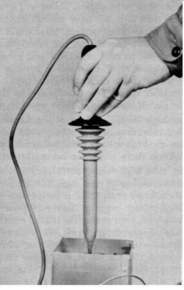
Fig. 617. Correct technique for using a high-voltage probe.
4. Connect the ground clip of the high-voltage probe to the negative side of the high-voltage supply. This is usually the chassis. Make this connection before starting high-voltage tests.
5. The safest place to make a high-voltage test is at the second anode terminal of the picture tube. The reason for this is that there is usually a large-value filter resistor (470,000 ohms or more) between the filament of the high-voltage rectifier tube and the picture-tube second anode. If you should accidentally touch the second-anode pin. the voltage drop across the filter resistor would give some measure of protection. The highest d .c. voltage point in any TV set is at the filament of the high-voltage rectifier tube. It is true that the voltage across the filament is about 1.25, but from either filament pin to chassis is maximum high voltage.
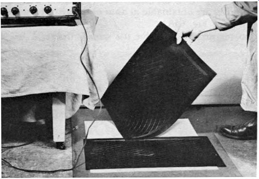
Fig. 618. A rubber mat is very inexpensive, high-voltage insurance.
6. You don't have to touch a high-voltage point to get a shock.
All you have to do is to bring your hand close enough. High voltages can discharge from sharp points (corona). High voltage can crawl along a dust path or through ionized air.
Keep one hand in your pocket.
7. Before doing any soldering or wiring in a high-voltage supply, make sure the set is off, and then discharge the high-voltage filter capacitor. A picture tube whose coating is being used as part of the high-voltage filter will discharge more slowly than a filter capacitor.
8. When measuring in the region of 30,000 volts or more, keep the probe at the high-voltage point until the meter needle moves up to its final reading. Do not keep the probe connected for an unnecessarily long time, since the probe resistor may heat, causing drift of the meter needle.
Remember, it takes less than 150 ma to kill a normal, healthy human being. A quick look at Ohm's law (E=IR) will show you that very little voltage is required to push that current through your body if its resistance is low enough.
Keep your body resistance as high as possible, and avoid any contact with the live circuits of a receiver. At times, unfortunately, many of us forget the fact that the live circuits may include the chassis or any grounded object (even the floor). Every service shop should have a wooden floor. Where work must be done in homes or other locations with cement floors, insulate yourself from the floor with rubber mats. Mats about 13 X 21 inches are obtainable at auto or department stores--inexpensively. (See Fig. 618.)
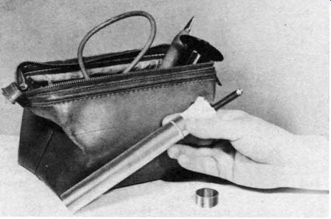
Fig. 619. The multiplier resistor in the probe is a barrier between you and
the high voltage. Take care of it.
Dry boards may be used for the same purpose. A few 1-inch-thick boards about 10 X 60 inches will provide a safe working platform. They should be stood on end to dry when not in use.
Don't depend on the wire insulation to protect you if the internal multiplier resistor should break down or arc over.
High-voltage probes are easier to carry, store and keep dry. if they are taken apart. With the probe dismantled the multiplier resistor should be kept in a toothbrush container lined with soft, dry cloth. A small zipper bag is an ideal carrying case (Fig. 619). The outside of the probe should always be wiped dry before and after use. Moisture inside the probe can be removed with a narrow bottle brush.
AMAZON multi-meters discounts AMAZON oscilloscope discounts