CHARACTERIZED by reliability, simplicity, flexibility, and ample power, this amplifier has a maximum undistorted (0.5%) output of 30 watts. The input for maximum output is 2.5 millivolts.
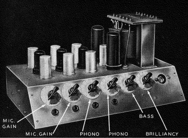
Fig. 1601. Front view of the high-fidelity amplifier. One of the two
phono inputs was later changed to a microphone input. All controls are
on the sloping panel.
Two novel features in the circuit are the tone control stage and the high-gain phase splitter. The input circuit is designed for three dynamic microphones and one crystal pickup, and not two of each as shown in the photograph, Fig. 1601. Simplicity is the keynote and only one microphone transformer is used, a 1:50 Mumetal-shielded type. Mixing is smooth and silent.
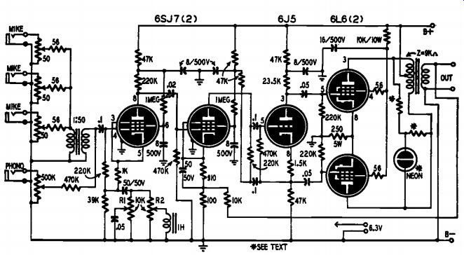
Fig. 1602. Schematic of the amplifier. The second 6517 uses the cathode
follower's high input impedance as a.c. plate load.
Tone control circuits
The outputs of the microphone transformer and pickup are applied in parallel between grid and ground of the tone control tube, a 6SJ7 (see Fig. 1602). The gain of the low-impedance mikes is controlled by 50-ohm pots. A 500,000-ohm pot is needed for the high-impedance crystal pickup. Variable negative current feedback is applied to this tube by the cathode resistors and associated networks.
The correct value of grid bias is obtained by returning the 220,000 ohm grid resistor to a tap in the cathode circuit.
When the moving contacts of the two tone control potentiometers, R1 and R2, are grounded, the impedance between cathode and ground is about 5,400 ohms and is independent of frequency; therefore the negative feedback is also independent of frequency and the gain is constant.
When the moving contact of potentiometer R1 is moved to the other end of its track, the network has an impedance which decreases with rise of frequency -3,500 ohms at 1,000 cycles, and 1,300 ohms at 10,000 cycles (see Fig. 1603). The corresponding decrease in the negative feedback with increasing frequency causes the gain to rise and the control to act as a treble boost. Fig. 1603 also shows the cathode ground impedance variations with the frequency, with potentiometer RI at the half-resistance and maximum setting. R1 at minimum indicates a constant impedance throughout the frequency range.
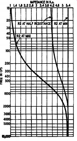
Fig. 1603. Graph at the left shows impedance variation of treble circuit
with bass control at minimum.
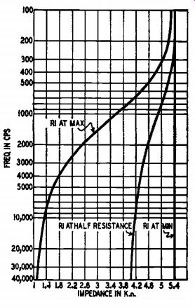
Fig. 1604. The graph at the right shows the impedance variation of the
bass circuit with the treble control set at a minimum.
By similar reasoning, potentiometer R2 is a bass boost. The 1-henry choke gives the network an impedance of 3,550 ohms at 500 cycles and 1,310 ohms at 50 cycles. Fig. 1604 shows the cathode-ground impedance variations with frequency, with both half-resistance and maximum settings of potentiometer R2. With R2 at minimum, the impedance is constant.
The resonant frequency of the choke and capacitor is 723 cycles; but there is no peak in the response curve at this frequency, even with both controls at maximum, because the tuned circuit is very heavily damped by the parallel resistances, R1 and R2. This tone control circuit, although simple, is extremely satisfactory. The table shows how it increases bass and treble response.
A novel phase splitter The next two stages are considered together. The first is a 6SJ7 operated so the stage gain approaches the amplification factor of the tube. This is achieved by making the plate load of the tube the extremely high input impedance of a cathode-follower phase splitter.
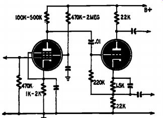
Fig. 1605. Conventional cathode follower phase splitter preceded by
a pentode.
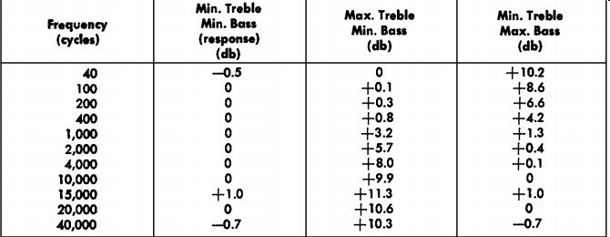
--------------- RESPONSE TABLE
The operation is best understood by developing the circuit from a conventional cathode-follower phase splitter preceded by a pentode amplifier whose gain is determined by the values of the plate load resistance and the B-supply.
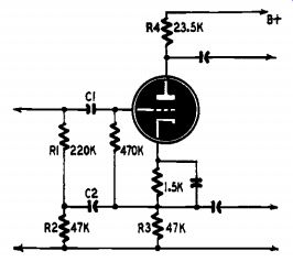
Fig. 1606. Re-arrangement of the phase splitter of Fig. 1605 for higher
gain.
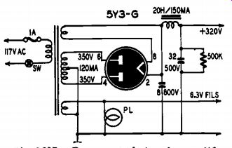
Fig. 1607. Power supply for the amplifier.
The input impedance of such a cathode-follower is approximately 10 times the impedance between grid and cathode. In the circuit of Fig. 1605 this is approximately 2.5 megohms, so that the input impedance of the phase-splitter does not affect the gain of the pentode. How ever, the maximum value of the plate resistance consistent with a reasonable plate voltage is about 500,000 ohms. This gives a maximum gain of 250 with a 6SJ7 and a plate supply of 300 volts. The gain of the phase splitter being about 0.9, the overall gain is 225.
The phase splitter of Fig. 1605 may be redrawn as in Fig. 1606, where C1 and C2 have negligible reactance at the lowest working frequency. The grid-cathode impedance is now 150,000 ohms (R1 being in parallel with the grid resistor), so that the input impedance of this cathode-follower is approximately 10 times 150,000 ohms or 1.5 meg ohms. If the grid end of R1 is connected to the anode of the preceding pentode and the ground end of R2 is connected by the B-supply, the a.c. conditions of the phase splitter are unchanged and the pentode sees the input impedance of 1.5 megohms as its plate load. The over-all gain is thus increased to about 1,000. The inherent unbalance is negligible if R2 = R3 = 2 X R4. Comparison of Figs. 1602 and 1606 shows that this is the arrangement used. The constructor may use several methods of obtaining the correct resistance. Possibly the easiest is to use two 47,000-ohm resistors in parallel for R4.
Output stage and B-supply
The remainder of the circuit is conventional. Two small resistors (56 ohms) are included in the screen feeds of the 6L6 output tubes for parasitic suppression and to limit screen dissipation. Considerable negative feedback voltage (about 20 db) is introduced into the cathode of the second 6SJ7 from the secondary of the output transformer. Extensive decoupling is used throughout to prevent positive feedback.
Because of its extremely high gain, the amplifier is very sensitive to noise and microphonics in the first tube. The latter noise is eliminated by rubber mounting the tube socket.
The power pack is conventional as seen from the circuit in Fig. 1607. A photo of the power supply is shown in Fig. 1608. The power transformer supplies 350-0-350 volts to a 5 1/3-G full-wave rectifier, and a 500,000-ohm bleeder is connected across the B-supply to discharge the electrolytic capacitor after switching off. A 1-watt resistor is adequate.
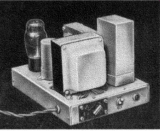
Fig. 1608. The power supply is a separate Unit.
As shown in the circuit, Fig. 1602, an output indicator is included in the amplifier. This consists of a neon lamp, with limiting resistors, connected across the primary of the output transformer. The 0.5-watt lamp, a common type of indicator for British standard 230-volt lines, was uncapped and fitted into the octal base of an old burnt-out tube with Plastic Wood. The values of the limiting resistors were adjusted by trial and error until the indicator is fully lit at 30 watts output.
Construction hints
For those readers who contemplate building a similar amplifier, the following constructional notes may be of interest. The chassis of both units are of .064-inch aluminum, and the two chassis measure 15 x 7 x 3 inches and 8 x 6-1/2 x 1-1/2 inches, respectively. The amplifier control panel is set at an angle and the six controls are grouped in a horizontal row, the four input jacks being placed below their respective mixer potentiometers. This, together with a symmetrical layout of the tubes and electrolytic capacitors, gives a neat appearance to the job. An under-chassis view is shown in Fig. 1609. Power is carried to the amplifier by a heavy-duty four-wire cable terminated in a female four-point connector. The speaker output is taken from two insulated binding posts at the rear of the chassis.
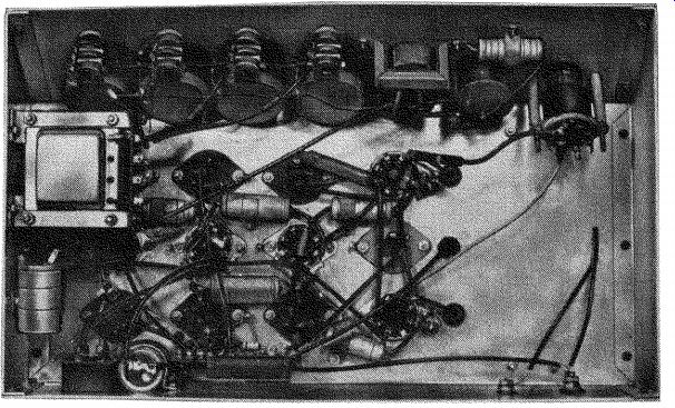
Fig. 1609. The symmetrical layout under the chassis gives the job a
very neat appearance.
While the general layout is not very critical, some precautions must be taken to keep the hum at the lowest possible level because of the amplifier's high gain. One good way to keep hum down is to make all the common ground connections to a single bus bar, then ground the bus bar to the chassis at one point only. This point should be at the input stages or where the signal level is lowest. The heater circuits should be wired with a pair of twisted wires. Do not ground one side of the heaters in the amplifier chassis. The power supply schematic shows one side of the 6.3-volt winding grounded. It is better to ground the centertap of this winding if there is one.
The photographs show the placement of parts, which is not very critical. All resistors and capacitors have 20% tolerance. The 250 ohm, 5-watt common bias resistor of the 6L6 output tubes largely compensates for any slight mismatch of the resistors in the phase splitter circuit. The 23,500-ohm resistor may be 22,000- and 1,500-ohm units in series. The two 50-uf electrolytic capacitors are mounted with their cans isolated from ground. All coupling, decoupling, and smoothing capacitors are rated at least 500 volts, as the B-supply reaches this value before the output tubes are fully conducting.