ONE of the most important considerations in appraising amplifier performance is how faithfully the system transmits audio impulses.
Only distortion measurements can establish quantitatively the degree of fidelity.
Distortion tests enable the designer to check the effects of circuit changes on reproduction. They are invaluable also to the service technician in determining the effectiveness of repairs and adjustments.
In routine maintenance work, the sudden appearance of small amounts of distortion, ordinarily not detectable by ear, usually points to the start of trouble in some component.
In the broadcast field distortion meters are a must by FCC rule.
Serious audio enthusiasts and technicians who build and service audio equipment are turning to the distortion meter for specific and accurate checks on amplifier performance.
Testing methods
The first distortion meter was a milliammeter in the plate circuit of an amplifier tube. Theoretically, there should be no fluctuation in the average plate current of a class A amplifier. At times, however, the meter needle will kick up or down from its steady-state value. Kicks of more than 10 percent of the steady-state reading indicate unsymmetrical amplification, with resulting distortion. The plate-current distortion meter indicates only that distortion is present; the remedy is still a problem.
The principle of modern distortion-measuring technique is simple.
A signal from an audio oscillator is applied to the amplifier under test. The output of the amplifier is fed to the distortion meter. This output contains the fundamental frequency of the oscillator, plus any harmonic distortion (multiple or sub-multiple frequencies) introduced by the amplifier. The output voltage is adjusted to a reference mark on the v.t.v.m. associated with the distortion-measuring equipment.
This is called the "calibrate" step. Next, the fundamental frequency is eliminated, leaving only the harmonics. The combined amplitude of these harmonics is then read directly on the v.t.v.m. as a percentage of the total output.
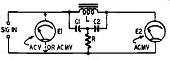
Fig. 1801. Basic distortion meter circuit. It is the familiar bridged-T.
In measurements of this type, perfect impedance matching between all components is imperative to prevent reflections that affect the accuracy.
The heart of the distortion meter is the means used to eliminate the fundamental frequency and leave all the harmonics for measurement. One method uses a bridge circuit. The bridge is highly effective, but requires costly precision components and very careful balancing adjustments. Another method is by means of a T or bridged-T filter network. This also requires balancing, and a switching arrangement for each frequency band, since a given set of high-Q filter components are effective only over very narrow frequency limits.
Of the several methods of measuring audio distortion, the fastest, as well as the one most favored in service and maintenance, is that of checking total distortion. The technician usually is not as much interested in the strength of separate distortion components (for example, second harmonic, third harmonic, fourth harmonic, etc.) as he is in the answer to his question, "How much distortion is present?" Furthermore, there seldom is time to check individual harmonics and to calculate the square root of the sum of their squares when distortion must be checked after each of many amplifier adjustments.
A widely-used basic distortion-measuring circuit is shown in Fig. 1801. This is the bridged-T network which is the foundation of one of the distortion meters described in this Section. The network components (L, C1, C2, and R) are chosen to provide a sharp null (zero transmission) at the test frequency. R is made variable and is preset closely for sharp null. When the Q of the circuit is kept reasonably high, the fundamental test frequency is eliminated completely and only the total harmonic voltage (E2) appears across the a.c. millivoltmeter.
In use, the amplifier or audio network to be tested is supplied with a signal from an audio oscillator or signal generator having very low distortion. The output of the amplifier then is connected to the input terminals of the network. The meter is switched first across the net work input terminals, as shown by the dotted lines, to read the amplifier output voltage (E1). This voltage contains fundamental and harmonics. The meter finally is switched to the output of the bridged-T network, and the small voltage (E2) due to harmonics is read. The distortion then is the ratio of E2 and E1 and is expressed in percentage as 100 (E2/E1). If the input voltage, E1, always can be set to a predetermined level for reference, the millivoltmeter can be made direct reading in distortion percentage, and no calculations will be required.
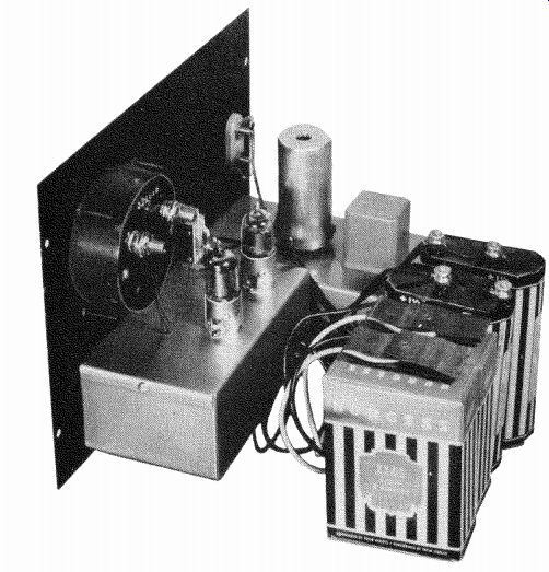
Fig. 1803. Distortion meter. Audio inductor and plug-in tuning unit
are seen at rear.
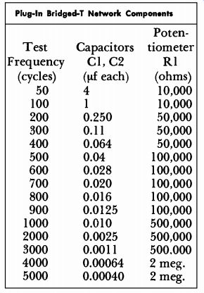
Table I Plug-In Bridged-T Network Components
Complete instrument
Fig. 1802. Distortion meter which combines sensitivity, low hum, complete suppression of fundamental and ability to operate on several audio frequencies.
Many amateurs and professionals have employed this method of distortion measurement, using homemade equipment. However, there are several difficulties common to almost all setups: (1) the a.c. meter must be capable of checking very small voltages at the output of the bridged-T network. These often are milli-voltages which cannot be read on the scales of ordinary v.t. voltmeters. For example, 1 volt may be obtained from the amplifier under test and applied to the input terminals of the distortion-checking circuit. In order to measure 1% distortion, the meter then must show 10 millivolts (0.01 volt) when connected to the bridged-T output. (2) Coil L (Fig. 1801) must have a higher Q than customarily is obtainable with the power-supply filter chokes often used in the circuit by experimenters. If the Q of the bridged-T circuit is not high, harmonics will be attenuated and the meter will not give a true indication of distortion. (3) Usually, no provision is made for easily changing the operating frequency to a new value. (4) Considerable inaccuracy can occur from hum generated by the power supply and picked up by the bridged-T choke.
The distortion meter shown in Fig. 1802 removes these shortcomings: (1) A sensitive electronic millivoltmeter circuit has been provided. This circuit requires no zero adjustment. The indicating meter is a comparatively inexpensive 0-1 d.c. milliammeter (reading linearly direct in distortion percentage -1, 10, and 100% full scale), and only 10 millivolts at the output of the bridged-T network is required for full-scale deflection when the range switch (S2 in Fig. 1802) is in its 1% position. (2) Hum has been eliminated by powering the voltmeter circuit with small, self-contained A- and B-batteries. Since the drain is low, long battery life may be expected. Battery operation also provides complete isolation. (3) Coil L is a special audio inductor. (U.T.C. type VI-C15) which has good Q and adjustable inductance.
(4) The test frequency may be changed at will with plug-in frequency units C1, C2, RI. The values given for C1, C2, and R1 in Fig. 1802 are for a test frequency of 400 cycles, since this frequency is supplied by most AM signal generators. Table I gives capacitance and resistance values for other common test frequencies between 50 and 5,000 cycles.
There is little point in checking beyond 5,000 cycles, since the harmonics of higher frequencies lie out of the range of most hearing.
Usually, three test frequencies, selected in the low, middle, and high portions of the audio spectrum (e.g. 50, 1,000, and 5,000 cycles), will give a satisfactory practical picture of amplifier behavior. It is convenient, for compactness and simplicity, to use plug-in frequency units. However, you can incorporate a switching "tuner" and enclose all components for 10 or more frequencies within the instrument case.
The input gain control allows the meter to be set to a reference level (such as 100%) when the meter is switched to read input voltage. Switch SI is a spring-return switch resting normally in the position shown, to connect the meter across the output of the bridged-T network. For initial adjustment, this switch is thrown to the right to connect the meter to the input.
The range switch, S2, gives the indicating meter three ranges--0-100%, 0-10%, and 0-1 %. At the 100% setting of the switch, the meter has a full-scale deflection of 1 volt, at the 10% setting 0.1 volt, and at the 1% setting 0.01 volt.
The millivoltmeter circuit is simple, employing a high-gain 11_14 pentode resistance coupled to a triode-connected 3S4 driver amplifier for the meter circuit. The full-wave meter circuit consists of a crystal bridge employing two 1N34 germanium diodes and two 100-ohm resistors. If a pair of matched 1N34's aren't available, use a 1N35 duo diode. The 100-ohm resistors must be matched within at least 1%. Since the 3S4 must be cathode-biased, the A-battery must be operated above ground. That is the reason for the separate A-battery for the output stage. There is no B-battery drain when the tube filaments are not lighted, so no switching is needed in the high-voltage circuit.
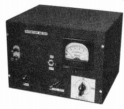
Fig. 1804. A front view of the distortion meter.
Construction details
The photographs, Fig. 1803 and Fig. 1804, show construction details of the distortion meter. The instrument is housed completely in a 10 x 7 x 8 inch standard metal cabinet. Tuning and millivolt-amplifier units are mounted on separate small box-type chassis. The chassis holding the amplifier measures 5-1/4 x 3 x 2 inches. The tuning unit chassis is 5-1/2 x 3 x 1-1/4 inches. Both of these chassis are enclosed on all sides and accordingly provide good shielding.
The small, shielded inductor L may be seen on the rear of the farther chassis. Directly in front of the inductor is the plug-in can containing C1, C2, and potentiometer RI. The latter is provided with a slotted shaft for adjustment through the hole seen in the top of the plug-in can. The plug-in foundation is a Millen 74001 assembly which has an octal base. The coil form is removed from this unit and the two capacitors and potentiometer are installed in its place. In order to fit into the small can, Mallory Midgetrol potentiometers (15/16 inch diameter) were used. If you are compelled to use larger potentiometers, the larger Millen 74400 plug-in cans may be employed. The latter are rectangular cans and, like the type 74001, are provided with octal bases for plugging into a standard 8-pin tube socket.
The A- and B-batteries fit snugly into the cabinet just to the rear of the amplifier chassis in approximately the position they are shown in Fig. 1803. They stand vertically.
The leads from the input binding-post terminals are shielded with braid.
Keep all leads in the meter amplifier as short as possible and use point-to-point wiring. Resistors R2, R3, and R4 must be of close tolerance, varying not more than 1% from specified values. Aside from these points, no special precautions are necessary in construction of the amplifier. In the plug-in units, capacitors C1 and C2 must be matched carefully and should be close to specified values (see Table I) as can be obtained. A glance at the list shows that a number of the capacitances are not stock values, but must be made up with suitable units connected in parallel (e.g., 0.028 uf required for the test frequency of 600 cycles would be made by paralleling 0.02 and 0.008). These capacitors must be high-grade, to insure high Q in the bridged-T network. By using metallized tubulars for the high capacitances, smallest physical size may be secured.
Initial adjustment
If the instrument has been wired correctly and good components used throughout, the voltmeter section will require no adjustment whatever. However, if desired, this part of the instrument circuit may be checked for voltage calibration and linearity. Remove temporarily the lead between C3 and Si and feed a series of accurately known calibration voltages between C3 and ground, checking the corresponding meter readings. A 1,000-cycle source, such as an audio oscillator, is recommended. In some instances, higher sensitivity might be obtained--full-scale deflection with less than 10 millivolts input with switch S2 at 1% position. However, the absolute voltage level is unimportant in this application. The important thing is that the voltage, whatever its level, be divided exactly by 10 and 100 by successive settings of switch S2.
Next, the frequency units must be adjusted to the corresponding operating frequencies. Here is one example, that of the 400-cycle unit.
(1) Switch on the distortion meter and allow about 5 minutes warmup time. (2) Set an audio oscillator to 400 cycles and connect its output to the distortion-meter input terminals. (3) Plug the 400-cycle frequency unit into the distortion meter. (4) Set switch S2 to its 100% position and advance the 500,000-ohm potentiometer gain control until a healthy meter deflection is obtained. (5) Adjust potentiometer R1 in the frequency unit for lowest obtainable meter reading (complete null). (6) With an 8-32 Allen wrench, adjust the inductance set-screw in inductor L for further improvement of this null. (7) Do not touch the setting of RI at any time afterward unless a routine recalibration is made. Also, do not retouch the setting of the inductance screw in the inductor L. (8) Successively plug in each frequency unit and adjust it to its particular frequency by adjustment of its potentiometer R1 only.
Operating the meter
Checking oscillator distortion: After warming up both the oscillator and distortion meter for at least 5 minutes, connect the oscillator to the distortion meter and set the oscillator output to the desired level.
(1) Set switch S2 to its 100% position.
(2) Plug-in a frequency unit for the desired test frequency and set the oscillator dial to that frequency.
(3) Set switch Si to its right-hand (input) position and adjust the gain control for full-scale meter deflection.
(4) Return switch S1 to its normal (output) position.
(5) Set switch S2 successively to lower ranges until an accurately readable meter deflection is obtained. This deflection, together with the setting of switch S2, will indicate the oscillator distortion percentage directly.
(6) Rock the oscillator dial back and forth slightly for an improvement in the meter dip.
(7) Repeat the procedure at several settings of the oscillator output control, since oscillator distortion often varies with output.
Checking amplifier distortion: Measuring the distortion of an amplifier is similar to the procedure just given for checking an oscillator.
There is an important preliminary point, however, and that is to check carefully the distortion of the oscillator which is to be used to supply a test signal to the amplifier. The oscillator distortion figure then must be subtracted from any distortion figure obtained for the amplifier.
When checking a complete amplifier system, connect the distortion meter across the loudspeaker voice coil (if you can stand the noise), since the speaker is the normal load of the amplifier. If quietness is a necessity, however, the voice coil may be replaced temporarily with a resistor having the same ohmic value and rated at twice the power output of the amplifier.
To check the amplifier: (1) Connect a low-distortion audio oscillator (whose distortion has been checked and recorded at each intended test frequency) to the amplifier input. (2) Connect the amplifier out put to the distortion meter. (3) Allow the oscillator, amplifier, and distortion meter to warm up. (4) Plug-in a distortion meter tuning unit for the first test frequency. (5) Set the oscillator to the same frequency. (6) Set switch S2 to its 100% position. (7) Set switch Si to its right-hand (input) position, set the amplifier gain control to the desired test point, and advance the gain control of the distortion meter for full-scale meter deflection. (8) Return S1 to its normal (output) position and change the setting of switch S2 for a readable meter deflection. (9) Rock the oscillator dial to deepen the null. (10) Read the distortion percentage from the meter deflection and the setting of range switch S2. (11) Subtract from this figure the distortion of the audio oscillator, previously determined. (12) Repeat the procedure at as many test frequencies and at as many settings of the amplifier gain control as desired.
----------------
Materials for Meter (400 Cycles)
Resistors: 2-100 ohms, 1/2 watt (matched with in 1%); 1-1,000 ohms, 1/2 watt; 1-3,900 ohms, 1 watt; 1-1, 1-2.7, 1-3.3 megohms, 1 1/2 watt; 1-20,000, 1-180,000 ohms, 1%, 1 / 2 watt; 1 1.8 megohms, 1%, 1/2 watt.
(Potentiometers) 1-500,000 ohms; 1-50,000 ohms (Mallory U33).
Capacitors: (Electrolytic) 1-10 pf, 50 volts (Miniature metalized tubular); 2-.06, 2-0.5 id, 400 volts; 2-1.0 pf, 200 volts; 1-0.5 pf, 600 volts. (Mica) 2-.004 Ø. Miscellaneous: 1-Adjustable inductor (UTC VI C15). Batteries: 2-67.5 volts, Burgess XX45 or equivalent; 2-1.5 volts, Burgess 2FBP or equivalent. Switches: 1-s.p.d.t., spring-return rotary; 1-single-circuit, 3-position, non-shorting. Meter: 1-0-1-ma d.c., Triplett 327-T or equivalent. Chassis; cabinet; dial knobs; input terminals; hookup wire; tubes; sockets, etc.
--------------
Special note regarding low test voltages: When the amplifier or oscillator under test delivers an output voltage of 1 or higher, the distortion meter can be set initially to 100%. Under this condition, 1% distortion then can be read at full scale when the range switch is at its 1% setting. On the same range, the first major division of the meter scale (0.1 milliampere) indicates 0.1 % distortion and the first small division 0.02% distortion. If the test voltage is lower than 1 volt but sufficient to allow the meter to be set to full scale with switch S2 in its 10% position, then 10% distortion is indicated at full scale when S2 is switched to its 10% position. When the test voltage is too low to permit setting the meter to full scale, simply divide the final indicated distortion figure, indicated by the meter, by the distortion indicated in the initial setting. Example: With switch S2 at its 100% setting, the meter can be set initially only to the 50% point. In the distortion measurement, with S2 subsequently set to its 1% position, the meter indicates 0.5 % distortion. The true indicated distortion then is 0.5 divided by 50, or 1%.
A new approach
With the basic principles of commonly-used distortion meters in mind, here is the theory and construction of a different type of instrument. This new distortion meter was developed in the electronics laboratory of the University of Wyoming. The new meter is inexpensive, easy to operate, and accurate within 2 percent. It can be used with inexpensive audio oscillators with no sacrifice in accuracy.
The new circuit eliminates the fundamental by phase cancellation.
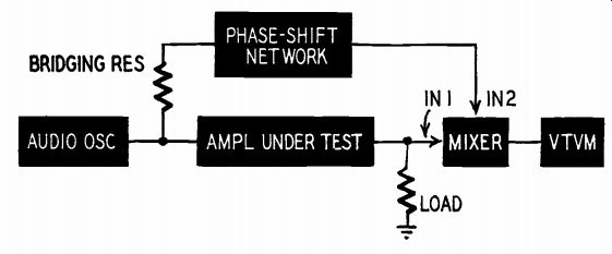
Fig. 1805. Block diagram of the simplified method of measuring harmonic
distortion.
If we impress two sine waves of equal frequency on the same circuit, a number of results may be obtained. If the two waves are in phase (in the same position in their respective cycles at any given time), they will add, and the measured voltage will be the sum of the two individual amplitudes. If the waves are exactly opposite in polarity (180° out of phase), the larger will cancel the smaller, and if they are of equal amplitude, they will cancel each other completely.
No doubt you have jumped ahead in your thinking, and see the basic principle involved: If the output of an amplifier containing a fundamental and harmonics is mixed with the correct amount of fundamental shifted exactly 180°, the resultant will contain only the harmonics.
Fig. 1805 shows the principle in block-diagram form. The oscillator output is applied to the amplifier. A phase-shift network is "bridged" across the oscillator output. (A bridging connection should not be confused with a bridge circuit. "Bridging" is a tem used in telephone and broadcast work to describe a high-impedance connection across a low-impedance circuit. Program monitors, volume indicators, and other testing devices are bridged across standard 600-ohm lines through high series resistances to reduce loading effects and provide a high degree of isolation. The v.t.v.m. is the most common example of a bridging device.) The impedance match between oscillator and amplifier is not affected by the bridging connection, but the amplitude of the signal going to the phase-shift network is small. The amplifier output is fed to a suitable resistance load, and the load voltage is applied to one input of the mixer. The output of the phase-shift network is fed to the other mixer input.
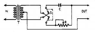
Fig. 1806. Fundamental phase-shift circuit.
Amplifier phase relations
In an ideal vacuum-tube voltage amplifier stage with a resistive load, the grid and plate voltages are exactly 180° out of phase. This relation ship is not true in practical circuits. Tube and stray capacitances, coupling transformers, capacitors, and reactors upset the perfect resistive condition. In a multistage amplifier, we may have different phase shifts in each stage. The shift-per-stage will also change as the frequency changes. In any case the shift-per-stage cannot vary more than 90° from the 180° ideal. Thus an amplifier with an even number of stages would have an ideal phase shift of 360°, a minimum shift of 180°, and a maximum shift of 540°. An odd number of stages would have an ideal shift of 180°, a minimum shift of 90°, and maximum shift of 270°. The phase-shift network in this instrument has two functions: (1) It provides a fixed shift of 180° to compensate for an odd or even number of amplifier stages; (2) it can be also varied over a range of approximately ±90° to make up for practical amplifier conditions.
The distortion-meter circuit

Fig. 1807. Schematic of the complete distortion measuring instrument.
The basic phase-shift circuit of the instrument is shown in Fig. 1806. This circuit has been borrowed from industrial electronic equipment. (The Westinghouse Industrial Electronics Reference Book explains the operation of this circuit in complete detail. It is available at most large public libraries.) Reversing-switch S gives a fixed shift of 180°. Smaller shifts are obtained by varying R. Fig. 1807 is the complete circuit. Ti is a line-to-push-pull-grids or plate-to-push-pull-grids type, with the highest possible step-up ratio. It need not be a high-fidelity type, but the secondary center-tap must be accurately balanced. Resistor R should match the input impedance of T1. R2 and R3 are equal bridging resistors. Their value is not critical and may be from 10,000 to 100,000 ohms. Higher values improve isolation but reduce the voltage to the transformer.
RI should be about 50,000 ohms. C1 may be from 0.01 uf to 0.1 uf.
Its value depends on the characteristics of Ti, and can be found with the help of an audio oscillator and a scope. Set the oscillator to 1,000 cycles and connect it to the network input terminals, and to one of the scope inputs (either vertical or horizontal). Connect the other scope input to X 1 , and shut off the internal sweep. Select C1 so that by varying R1 the scope pattern changes from a diagonal line to an ellipse, and then to a circle.
A 6N7 mixer is shown in the diagram, but any twin-triode type (6SL7, 6SN7, 12AT7, or 12AU7) may be used. R4 and R5 may be 500,000-ohm volume controls, or a T pad may be substituted for R5 if a calibrated attenuator is preferred.
The mixer is operated as a cathode follower. There is no voltage gain, but the stage has no measurable distortion. X1 and X2 are test jacks for oscilloscope checks. The 6SJ7 is a conventional resistance coupled amplifier, except that the cathode resistor is double the usual value because of the direct-coupled input. X3 is the terminal for the v.t.v.m.
Testing and operation
After a complete continuity and voltage check, connect a v.t.v.m. to X3, and short out both mixer inputs. Any reading on the meter indicates hum or noise in the instrument, which must be tracked down and eliminated.
W hen the unit is in perfect working order, connect an audio oscillator to the OSCILLATOR INPUT terminals and check the controlling effect of R4 on the output. At least 1 volt output should be obtained through the phase-shift circuit. Next, check the amplifier input section of the mixer in the same way.
Actual harmonic distortion measurements are carried out in the following way:
1. Connect the audio oscillator to the input of the amplifier under test, and bridge the phase-shift circuit across the input as shown in Fig. 1805. Adjust R4 for full-scale reading on the highest possible range of the v.t.v.m. plugged into X3.
2. Disconnect the bridging circuit fro m the input to the amplifier and short out the bridging input terminals. Connect the amplifier load resistor to the AMPLIFIER INPUT of the mixer, and adjust R5 for the same full-scale reading as in step 1.
3. Restore the bridging connection across the input to the amplifier and adjust R1 for minimum output. If the v.t.v.m. pointer goes off scale, reverse S and adjust R1 again for mini mu m output voltage.
4. Repeat steps 1, 2, and 3 for absolute mini mu m reading. T he final reading is the harmonic distortion in volts. For maxi mu m accuracy, the v.t.v.m. m ay be switched to a lower range only after steps 1, 2, and 3 have been completed.
The final voltage measurement may be converted to a percentage by the formula:
% Distortion - 100 E_min E rna .
Distortion in the audio oscillator itself will not affect the accuracy of the measurements, since the original signal is completely canceled in the mixer if the final balancing adjustments are made with care.
--------------
Materials for Measuring Se
Resistors: 1-510,000 ohms, 2-100,000 ohms, 2-10,000 ohms, 1-2,200 ohms, 1-1,000 ohms, R, R2, R3 (see text) 1 / 2 watt; 2-500,000-ohm potentiometers.
Capacitors: (Paper) 1-0.25 µf, 1-0.1 uf, 1-0.05 400 volts; C1 (see text). (Electrolytic) 1-20 uf, 25 volts, 1-8 µf, 150 volts.
Miscellaneous: 1-6N7 tube; 1-65.17 tube; 1 push-pull input transformer (see text); 2 octal sockets; chassis, connectors, terminals, solder, hardware; power supply--100 volts d.c. at approximately 20 ma; 6.3 volts a.c. or d.c. at 1.1 amp; 1 d.p.d.t. switch.
-----------