THE function of a tone control used to be wider than in modern equipment. This was before the day of equalizers available with modern equipment to compensate for recording characteristics. At one time this had to be taken care of in the tone control.
Why tone control? Any modern recording or radio channel has some tone-compensation system. This is to adjust program balance between high and low frequencies, to compensate for peculiarities in the studio reverberation characteristic or any other cause that may produce an apparent unbalance, excess or deficiency of high or low frequencies.
However, the home also has acoustic characteristics which lend coloration to the reproduction. Adjustment of tone balance is arbitrary because the factors that contribute toward the coloration are complex. The reverberation characteristic and frequency discriminating factors of both the recording studio and the listening room are usually far from being a smooth deviation that can readily be corrected by a simple tone-control system. As a result the best sense of balance in an overall system, taken from an original performance in the recording studio to the reproduction in a particular living room, must take into account the complicated acoustic characteristic of both rooms. The overall tone compensation needed should be a function of both the recording or broad casting studio and the listening room.
The compensation put in at the recording or broadcasting end is adjusted to achieve the best sense of balance in the monitoring booth attached to the studio, usually made as acoustically "color less" as possible without making it unnaturally "dead." It might seem, then, that all we need is a fixed tone compensation to suit the acoustic properties of the listening room in which the pro grams are heard and all programs should automatically come through with a good impression of balance.
This does not always produce the best results because acoustic colorations can interact. One studio may naturally emphasize the same groups of frequencies that our living room does, maybe at the high-frequency end. If the program from this studio is played without suitable adjustment to our tone compensation, this combination will make the overall effect seem excessively "live" over the range of frequencies where these peaks occur. Another studio, with the same average overall characteristic in this region, may tend to emphasize frequencies that would fall between those the living room emphasizes, with a resulting overall effect smoother than the average reproduction over the same system. Although, on some other criterion, such as a well-designed monitoring room, both studios might appear to need the same degree of tone compensation for the high-frequency end, in our living room the second program needs high-frequency accentuation to bring up the brilliance while the first one seems too brilliant and the high frequencies need playing down a little.
The modern trend in recording studios is to have a uniform reverberation time over the audio spectrum, considerably shorter than usual for an auditorium of corresponding size. Reverberation and characteristic coloration are then added by external means under careful control. This does produce program material basically within narrower tolerances, as regards apparent balance, and thus requiring practically no adjustment in any one living room between one piece of program recorded under these conditions and another under similar conditions.
While this may seem ideal, it is not always satisfactory. It gives what may be defined as high fidelity and does present a true impression of all the instruments. But some programs achieve some of their character due to the auditorium in which they are performed. Each of the famous ones, like the Albert Hall in London, has its own character due to the acoustic properties of the building. The acoustic background is as much part of the performance as the faint background contributed by the audience, an occasional cough, stirring of feet or applause. If the purpose of the recording or transmission is to give the listener the impression of being present at such a performance, removal of these incidental sounds and the general acoustic characteristic will destroy the illusion.
This leaves us with the fact that, even on modern high-fidelity wide-range recordings, it is desirable to have some degree of tone compensation for both high and low frequencies if we are to achieve the best impression of realism in our homes.
Other tone-control functions
In deciding what circuit to use, consider the tone control function. Sometimes it is called upon to get the best possible reproduction from an originally poor program source: for instance, an old 78 rpm recording that does not have any recorded frequencies much above 6 kHz and is accompanied by considerable needle scratch or an AM radio transmission which has its frequency band limited by the number of channels squeezed into the broad cast band. The desirable bandwidth may vary from program to program according to the transmission conditions or the state of the record. It is desirable to have a flexible tone control that will make the best of the high frequencies present in the program without bringing out too much background noise with them.
A similar function is sometimes required at the low-frequency end, due to unwanted hum present on the program material. For example, some of the older recordings, made before the desirability of reproducing extremely low frequencies was recognized, may have considerable hum from the recording amplifier. In "antiquated" reproducing systems this hum was not noticeable. The system did not reproduce appreciably down to this frequency.
However, the recording may have low frequencies in the region of say 80 to 100 Hz which we want to make the best of. So a flexible tone control that will achieve this may be helpful at the low frequency end too.
If you want to pick off the audio from your TV set and play it through the hi-fi system, you will probably have to rework the audio section of the TV set, to reduce the hum level or else use a compromise setting of the low-frequency control to get satisfactory low-frequency reproduction without excessive hum. Most TV sets rely on the fact that their speaker doesn't reproduce much in the region of 60 Hz, hence have a smaller amount of smoothing (or other form of hum elimination) than necessary for a hi-fi system.
A control designed merely to vary the general level of the low frequency end would need to be turned down so the whole program is noticeably bass-deficient before the hum is satisfactorily eliminated.

Fig. 1001. Three ways in which high-frequency tone control, using simple
R-C circuits, can be made to vary.
Other factors
These are the practical factors to consider in deciding upon a tone control circuit. The choice should also take into account the possible distortion that the amplifying stages associated with it can introduce. It may inject different types of distortion since the circuit tends to distort one group of frequencies-the extreme low, middle or the high end, more than other regions. Also, consider the possible effect on IM as well as harmonic distortion.

Fig. 1002. Corresponding ways in which low-frequency tone control can
vary.
The dynamic range is a factor in selecting a tone-control circuit, especially in deciding where to put it in a system. Any tone control needs to have some "headroom" if it is to provide boost at some frequency. It should be able to amplify, without producing distortion, considerably above the maximum level normal over the greater part of the frequency range. So the dynamic range of circuits incorporating tone controls needs to be somewhat wider than that of stages used for straight amplification. For this reason it is good to place the tone control after the major volume control so the level of the program material passing through the tone control is reasonably constant compared to the reproduced level. This will avoid requiring excessive dynamic range to take care of the margin of boost required and the variation in program level from the different sources (and the different listening levels required as well).
Response form
The simpler tone controls utilize resistance and capacitance elements that produce a kind of step response similar to that from which equalizers are built. Step responses are used for effective boost while capacitances in a position to produce rolloff reduce the level of low or high frequency.
But circuit response can be changed in more than one way by the adjustment of the control. Fig. 1001 shows basic ways of varying the high-frequency response. At A the amount of boost or roll off is adjusted, but the frequency at which either begins to take effect is constant. At B the amount of boost or rolloff is constant but the frequency is shifted. At C the response variation goes between the two; both the amount and the frequency are changed to produce a smooth transition from maximum boost to maximum rolloff with almost proportionate variation all the way, above about 2,000 Hz.
Fig. 1002 shows the same variations and characteristics applied to the low-frequency end.

Fig. 1003. Ways in which high-frequency peaking circuits ca11 change
their response. Curves using the same critical frequency are linked by
the dot-and-dash lines. Usually resistance varies height or rolloff,
while changing 1, or C alters the critical frequency.
For simpler controls aimed at correcting for slight deviations in good high-quality modern recording or transmission, circuits pro- viding this kind of response variation are quite adequate. For controls intended to make the best of poorer conditions, peaking and vari-slope type circuits are sometimes advantageous either as an alternative or an additional means of control.

Fig. 1004. When peaking is varied by using feedback over a two stage
amplifier, this kind of frequency response change can be expected.

Fig. 1005. Variable slope rolloff is sometimes a useful feature.
There are two ways of producing both varieties of circuit. One uses inductances as well as capacitors while the other employs feedback to achieve a similar kind of interaction. The peaking response can be varied in several ways as in the step circuit. The critical frequency and also the amount of peaking can be adjusted (Fig. 1003).
Using inductances and capacitances together, the frequency of the peak or rolloff is determined by the combined values of Land C, usually fixed or adjustable in steps, while the amount of peaking or rolloff is adjusted by the resistances. Another variation changes the amount of peak and the frequency at the same time (Fig. 1004). This is more conveniently produced with the feed back type of control, using only resistors and capacitors.
The remaining type uses a variable-slope rolloff. For this there are two approaches also but both use a fixed frequency, deter mined by the reactance components, and adjust the slope of the rolloff by damping or partially bypassing the overall reactive phase-shift effect. The frequency response variation for one particular frequency is shown in Fig. 1005.
These are the responses that can be produced. A complete arrangement can consist of any one or two of these controls or a combination of as many as desired.
Simple step circuits

Fig. 1006. The simplest circuit for making high frequency tone control,
including boost and rolloff.
Fig. 1006 shows the simplest possible arrangement of a high-

Fig. 1007. When the circuit of Fig. 1006 uses R1 having four times the
value of R2, this is the response variation produced.
frequency control giving rolloff and boost: two resistors, a capacitor and a potentiometer. If the resistors are of equal value, the maximum boost is 6 db. Usually a bigger boost than this will be desirable as a maximum. But, with this particular value, the boost and the rolloff frequencies at maximum and minimum settings coincide. If larger resistors are used for R1 and R2, say a ratio of 4 to 1, to give 14-db maximum boost, the frequency at which the maximum boost starts to take effect will be one-fourth the frequency at which maximum rolloff begins (Fig. 1007).

Fig. 1008. The addition of an extra capacitor (C1) over comes the unbalance
shown in Fig. 1007, to some extent.
This can be equalized to some extent by putting a capacitor in series with the top end of the potentiometer so that, at maximum boost, there is an additional capacitor in series with the one connected between the slider and the junction of the fixed resistor.
This means the effective capacitance in the circuit changes according to the position of the slider on the potentiometer.
One desirable feature about any tone control is that it should be possible to obtain a flat frequency response, preferably at some setting of the variable control, so adjustment can be taken right through flat. Otherwise the only way to achieve flat for comparison is to switch the tone control out of the circuit altogether.

Fig. 1009. The circuit of Fig. 1008 can never give a level response
at any position. The nearest approach is seen here.
With the circuit of Fig. 1008 the nearest approach to flat response occurs when the potentiometer slider divides its resistance in the same ratio as the fixed resistors. Then the voltage division at mid-range frequencies and at the ultimate high-frequency end is identical, since the capacitance in series with the top end of the potentiometer changes progressively from open to short circuit. But at a frequency where the capacitive reactance is approximately equal to the resistance of the potentiometer there is a 45 ° phase difference between the open-circuit voltages at the junction of R1, R2 and the potentiometer slider. The latter voltage is lower than the other by 3 db. Connecting the capacitor between the two points will make a dip in the overall response, de pendent on the relative value of the resistances for the fixed and variable components. (Fig. 1009). An advantage of this circuit, compared to the next one, is that it is possible (by controlling the value of the capacitor in series with the top end of the potentiometer) to use a boost frequency different than the rolloff frequency, which is controlled by the value of the capacitor in series with its slider, and still achieve an approximately similar approach to level response in the middle position.

Fig. 1010. This circuit, using symmetrical choice of components, can
give the range of responses shown in Fig. 1001-A.
Provided all the values are in the same proportion, the circuit of Fig. 1010 produces a flat response at a correct middle setting.
Also, the frequency of maximum boost is the same as that where rolloff takes effect. Thus it achieves the response variation of Fig. 1001-A. To do this the ratio of R1 to R2 must be the same as that of C2 to C1. In other words, the reactance of C1 to C2 should have the same ratio as R1 to R2. The point of rolloff or commencement of boost is where the reactance of C1 is equal to R1 and the reactance of C2 to R2. Because of its ability to produce a uniformly flat response at one position of the control, this circuit is quite popular. It is often used with the values divergent from this ratio to vary the boost and rolloff combination obtainable.
An intermediate position, then, can never produce a flat response.

Fig. 1011. A switched circuit that gives the response variation of Fig.
1001-B.
To get the response of Fig. 1001-B, the only method is to change the capacitance values, because the constant boost value means the circuit resistance values must be constant. The only practical technique is to use a switched arrangement such as that in Fig. 1011.

Fig. 1012. Addition of a variab1e resistance gives greater versatility
to the circuit of Fig. 1011; Fig. 1013. Using a two-pole switch, a response
variation combining the features of 1001-A and -B can be produced.
A fairly comprehensive tone control can be made by combining the two. A simple way of doing this uses a variable resistance to adjust the amount of boost or rolloff by putting the resistor in series with the switch slider (Fig. 1012). But this does not give adjustment through flat. There is a flat position but it is isolated from the boost and rolloff positions. An alternative combination that uses a switch to select frequency and a potentiometer to ad just amount of boost or rolloff, and which does go through flat, is shown in Fig. 1013. It achieves a variation of the frequency of boost or rolloff by the switch (as in Fig. 1001-B) while the amount of boost or rolloff (Fig. 1001-A) can be adjusted by the potentiometer. In this way a considerable variety of responses can be obtained.
There are advantages in using two controls to get greater versatility, but corresponding disadvantages. The fact that two knobs have to be adjusted to achieve a desired response (only high-frequency response, remember) means that it is less likely that the best response will be obtained. A single knob that gives a range of characteristics of better average desirability, makes the control simpler and reduces the chance of seriously incorrect settings.

Fig. 1014. A high frequency control using a two-gang potentiometer that
produces response variation of the type, Fig. 1001-C.

Fig.·1015. Showing the effect of controls using different tapers in
Fig. 1014: A is the variation using linear taper, B with log taper, complementary
(one direct log, one inverse log).
Fig. 1014 shows a circuit using a ganged resistance arrangement that varies both the turnover point and the amount of boost or rolloff, producing a response variation as in Fig. 1001- C. R1 and R2 are potentiometers. While a reasonably good control can be made using linear potentiometers, there is an advantage in semi-log or full log tapered controls. One should be inverted taper so that, at a middle setting of the control, each capacitor is shunted by about one-tenth of its resistor, while about nine-tenths of each resistor is in the circuit. Fig. 1015 shows the ranges of control, using a pair of linear potentiometers (A) and a pair of complementary logarithmic potentiometers of standard taper (B). Turning to arrangements to produce a straightforward bass boost or roll off, Fig. IO 16 shows the only way to vary bass roll off directly. This necessitates changing the coupling capacitor for each rolloff required. Using a resistor in shunt with the rolloff capacitor produces the same rolloff point but limits the rolloff to a degree of stepdown. If a coupling capacitor is required to produce de separation, as when coupling from a plate to a following grid, two capacitors should be used: a larger one to provide de blocking while the smaller one for variable bass cutoff has the variable resistor in shunt with it.
If the variable resistance goes completely open-circuit, the roll off is that provided by the capacitor but, as soon as some resistance is in shunt with the capacitor, the rolloff is limited to a stepdown response. Short-circuiting the capacitor produces a rolloff at the position determined by the main coupling capacitor, which for the purposes of tone control design should be below the audio-frequency range.

Fig. 1016. How bass rolloff is effected: circuit A selects the rolloff
frequency by switching; circuit B modifies the rolloff to a step-down
of variable depth; circuit C includes a de blocking capacitor.
Bass boost is provided by a capacitor in the bottom end of an attenuation arrangement (Fig. 1017). This is similar to the arrangement for equalizer circuits. The amount of boost can be adjusted by using a variable resistor directly across the capacitor.
When the capacitor is short-circuited, there is no boost. Maxi mum boost is secured by making the resistor a high value, approximating an open circuit, for the lowest frequency in the audio band.

Fig. 1017. A simple adjustable bass boost circuit.
Fig. 1018 combines the rolloff and boost arrangements to use one variable resistor for the response of Fig. 1002-A. The value of the potentiometer should be very high compared to either R1 or R2, unless an appreciable portion of the boost or rolloff is to be sacrificed by its presence.
This is a detrimental aspect of the circuit because it often dictates the need for a potentiometer of several megohms to avoid deteriorating the maximum boost condition. Usually the grid of the following stage has a maximum permissible circuit resistance, which makes this value impossible. So a compromise has to be accepted.
However, a mitigating factor is that the loudness contours of human hearing converge at the low-frequency end. Consequently a certain amount of bass boost is more effective than the same amount of treble boost. This means that some of the available boost can successfully be sacrificed by using a lower-than-ideal value for the potentiometer of Fig. 1018.

Fig. 1018. The commonest bass, or low-frequency tone control circuit.
It gives the response variation of Fig. 1002-A.
The frequency where the boost or rolloff begins to take effect is determined by making the reactance of C1 equal to R1 and the reactance of C2 equal to R2.
Fig. 1019 shows an arrangement that gives switched control to achieve the response variation of Fig. 1002-B. This requires separate capacitors to give each position of boost or rolloff.
Fig. 1019. A switched tone control circuit giving the response variation of Fig. 1002-B.
For the circuit of Fig. 1014, producing the combined response of Fig. 1001-C, the important part of the potentiometers, affecting both the frequency and the amount of boost or rolloff, is that in parallel with the capacitors, or the part from the slider to the center point of the circuit. The other section of each potentiometer serves only to pad out the circuit so the mid-band attenuation is kept constant as the control is turned. The only way to get the same kind of variation in response shaping at the low end of
the range is to use complementary variable resistances in series with a pair of capacitors. The relative values of the pair of capacitors will then determine the attenuation at the extreme low frequency end of the range while the attenuation in the center part of the range will be secured by the relation between the two components of series resistance. (Fig. 1020). While this will produce the kind of response variation of Fig. 1002-C, it will also vary the apparent gain of the amplifier drastic ally. At maximum boost the gain will be almost zero while at maximum rolloff the gain will be almost the full gain of the stage, without any attenuation in the mid-band region.

Fig. 1020. A low-frequency circuit producing the variation of Fig. 1002-C.
This changes mid-band gain drastically.
The circuit of Fig. 1021 overcomes this to some extent. The maximum boost is limited by putting a fixed resistor R2A in series with R2 so the mid-band attenuation at maximum boost is limited. A third potentiometer is ganged to these two to offset the change in mid-band attenuation.

Fig. 1021. Addition of a third variable to the gang of Fig. 1020 helps
overcome the gain change.
Rut it still is not constant.
To get the optimum effect, the best taper to use is complementary semi-log. This will give the best approach to the constant mid-band gain and a maximum variation in the characteristic.
Use of a full-log taper is likely to produce much more variation with gain as the setting is adjusted. It will also require a considerably greater overall attenuation, but it will give a greater range of control. But, whatever type of control is used, the mid-band gain does not stay truly constant as it does with the corresponding high-frequency control. This method of adjustment is scarcely recommended for the low-frequency end for this reason as well as the fact that it is more expensive because it requires a three gang rather special type of potentiometer.
Practical considerations
Fig. 1022. Two circuits that combine the arrangements discussed for both high- and low-frequency tone control: (A)--A circuit using the simplest continuously variable types, combining Figs. 1010 and 1018; (B)--A more elaborate circuit using switching to produce variations as at Figs. 1001-C and 1002-C.
A typical complete circuit needs to combine the step-boost and rolloff responses. Fig. 1022 shows two straightforward circuits that do this. In applying these to a practical amplifier certain factors need attention. They need to be fed from the plate of a preceding stage and also to connect to the grid of a following stage. Also the grid-circuit resistance of the following stage must not exceed the permissible value at maximum bass boost.
In calculating the overall response available remember that the plate circuit impedance of the preceding stage modifies the calculations. The plate circuit resistance is, of course, the combined resistance made up of the coupling resistor in parallel with the ac resistance of the tube. This will limit the maximum high-frequency boost because the capacitor shunting the upper end of the attenuator does not bypass this source resistance so there is still some attenuation at the extreme high end where, according to the idealized form, the attenuation should be short-circuited by C1.
Usually the source resistance will not have too much effect on the available bass boost and rolloff. What limits the available bass boost and rolloff is the value of the control resistor used for this purpose. This is determined by the permissible grid-circuit resistance for the following stage.
By careful choice of values, it is possible to achieve an equal degree of boost at both ends of the frequency response. An alternative choice of values can produce any combination of available boost for the system in hand with all these circuits the available amplification with maximum boost will be that much more than in the mid-frequency range. This, of course, should be an obvious statement. It means, however, that there must be this much attenuation in the middle of the band which is returned to some extent by the boost circuit.
Some disparage the use of the word "boost" because they con tend it implies the gaining of something for nothing. However this is not the intention here. The word boost is considered more satisfactory than any other term because we really consider the response relative to the apparent loudness in the middle of the band. If the apparent gain of an amplifier is greater at the extreme low- or high-frequency end than in the middle frequencies (which determine the apparent loudness of the program material) then the audible effect is that the low frequencies or high (as the case may be) are boosted, compared to the general loudness level.
The general loudness level may have to be attenuated, and the extreme low or high frequencies not, and thus the term boost may be regarded as academically incorrect. However, it is more acceptable than the thought of attenuation, rolloff or cut, which does not convey an accurate idea of its effect on performance.
Definitely, bass boost cannot be regarded as synonymous with treble cut, and vice versa, as some sticklers for "accurate terminology" insist! The tone-control circuit should be so placed that distortion does not occur at any position. If boost is required, the implication is that these frequencies are deficient and thus increased amplification of these frequencies is unlikely, in itself, to cause distortion. So it is reasonably safe to design a circuit on the basis of the levels in the mid-band. This may not always be true at the low-frequency end, however, where boost may be employed to make the frequencies audible, even though the power level may be fairly high.
Increased sensitivity of the human ear at the high-frequency end means that the energy, and hence voltage level, even when boost is applied, will still be relatively low. Application of boost to a program with appreciable energy at the high-frequency end would be most distressing to listen to.
An alleged disadvantage of the tone control circuits we have discussed is that distortion is cumulative; that is, it is not possible to apply feedback to reduce distortion. The only way to minimize distortion is to design each stage for minimum distortion as a straightforward amplifier. Of course it is possible to apply a degree of feedback over that stage by using cathode degeneration.
If the maximum boost is of the order of 14 or 15 db, (usually considered acceptable) then the stage before or after need have no more gain than this, to replace the loss in the network. This means that some gain can usually be sacrificed to linearize the amplification by cathode degeneration. A large cathode bias resistor, one that is a considerable fraction of the plate coupling resistor value, will produce this degeneration. The bias resistor is not bypassed.
This reduces the amount of distortion produced in this stage al though there is a limit to its effect: use of too large a bias resistor will overbias the tube. So there is an optimum choice for the circuit.
To improve the design still further a cathode follower can be utilized to eliminate the source-resistance problem. Alternatively, two stages of amplification can give a very considerable gain--between the preceding volume control and the tone control circuit.
This provides an opportunity to use a large amount of negative feedback to reduce distortion due to the curvature of the tubes.
Feedback types
The disadvantage of this combination is that gain has to be thrown away twice: once to minimize distortion in the amplification and again to provide headroom for the low- and high-frequency boost. It was this thinking that gave rise to the introduction of feedback-circuit tone controls (Fig. 1023). Instead of con trolling the frequency response in the forward gain of the amplifier, between stages, the frequency-selective network is placed in the feedback.
In basic theory the amplification has no frequency discrimination; only the feedback does. In feedback theory, if the loop-gain factor A_Beta is large compared to 1, the overall gain of the amplifier is approximately equal to 1/p. In other words, it is almost independent of the internal gain of the amplifier, A, and principally dependent on the feedback fraction, p. So a simplified explanation of the action of feedback tone control says that we place a frequency-discriminating network in the feedback section and thus produce an inverse response for the overall amplifier gain.
Unfortunately, this approximation is based on simple algebra, which takes no account of phase shift. Using algebra, without incorporating the operator j, the feedback seems to be either positive
or negative. We can take the feedback factor as either 1 + A_Beta or 1 - Ap. In practice A_Beta is a complex quantity involving a phase angle, particularly when frequency-discriminating elements are included to produce a tone-compensation arrangement. Then A_Beta is neither positive nor negative but a complex quantity which may be regarded as something in between, but still a large quantity, a long way above zero.

Fig. 1023. Illustrating the basic concept behind feedback tone control.

Fig. 1024. A possible circuit utilizing feedback over one stage.
In the case of equalizer circuits, the design can be taken in stages and a satisfactory overall response achieved. With a tone control circuit, where variation in response is required, a little more care is necessary because the interaction must produce the right kind of variation in response at all points.
There are basic limitations to feedback tone controls. The maximum range is set by the gain of the section over which feedback control is applied. Suppose the section gain is 26 db. Feedback can cut the mid-band gain by, say 14 db, to 12 db. Progressive removal of feedback can then give 14-db boost. But progressive increase of feedback to p = 1, will give only a maximum cut of 12 db. So the maximum difference between boost and cut is the section gain, in this case 26 db. Some overcome this by using feedback only for boost, then using a simple cut circuit elsewhere for the other part.
Feedback over just one stage, from the plate to the grid, can be used (Fig. 1024). Here a resistor is interposed between the plate of the preceding stage and the feedback point to permit adequate resistor values to be used for the feedback network and to prevent the preceding stage from causing distortion due to the low effective resistance load presented at some frequencies by the feedback arrangement. This uses essentially the same circuit configuration as the forward control network of Fig. 1022-A, except that, instead of feeding the following stage, it feeds back to the grid of the same stage.
Thus the feedback network inverts the response achieved. As there are no additional coupling reactance elements other than the single coupling capacitor, it is quite possible to achieve a satisfactory control response range within the limitation of stage gain. It is necessary, however, to insure that the components that adjust the feedback response do not appreciably modify the for ward gain characteristic due to the loading effect on the previous stage coupling; otherwise the tone-compensating effect is some what nullified. That is the reason for the additional resistors in the circuit.

Fig. 1025. An improvement on the circuit of Fig. 1024 that makes the
circuit double-acting in its tone control effect.
By using the plate-circuit feed from the previous stage as the "bottom" end of the feedback element, as far as frequency discrimination is concerned, the control becomes double-acting. Half its effect is due to a change in coupling between stages and half to feedback (Fig. 1025).
By using two stages (Fig. 1026), the feedback can be taken from the plate of the second stage to the cathode of the first stage. This serves to isolate the effect of the tone-compensating components from the feed from the preceding stage, which was a problem in the circuit of Fig. 1024. However, the fact that there is an additional stage, with its coupling capacitor and stray capacitance, means that the response contributed by these, (particularly phase effects in the forward part of the amplifier) interacts with the response of the feedback arrangement. This must be taken into account in designing the overall performance.
A well-designed feedback tone control does have the advantage, particularly with regard to low-frequency boost, on the score of distortion. The maximum amount of feedback is attained for the greater part of the frequency range. If more low-frequency response is required, some of the feedback is removed to achieve the necessary low-frequency boost. This means that the distortion of the low frequencies may be somewhat increased in comparison to mid-range frequencies. Won't this introduce intermodulation, too?

Fig. 1026. A feedback tone control, using two stages, from plate of
the second to the cathode of the first.
Fortunately, the fact that the mid-range frequencies employ a greater amount of feedback means that intermodulation effects, normally introduced in an amplifier at low frequencies without feedback, will be minimized by the feedback according to the amount available at the middle frequencies-the ones which would be modulated. The fact that the curvature may introduce fairly low-order harmonic distortion of the low frequencies is itself practically impossible to detect. We usually hear the extremely low frequencies principally by their harmonics anyway. So a little more or less of second-harmonic distortion of the lowest frequencies is comparatively unimportant, provided it is not accompanied by the much more irritating intermodulation distortion that usually accompanies harmonic distortion.
This is where the feedback tone-control arrangement helps particularly by minimizing the intermodulation distortion, although it may not reduce the harmonic distortion to the same extent.
For the dynamic range situation, the feedback tone control is quite similar to the direct type and must be treated accordingly in selecting the point in the amplifier at which to apply it.
Peaking types
The simplest circuit for peaking control can, in theory at least, be built around an interstage or some other type of transformer.
Low-frequency peaking can be produced by resonating the coupling capacitor with the primary inductance of the transformer.
The degree of peaking or rolloff can be adjusted either by varying the source resistance, which in this case consists of the plate resistance of the tube and the coupling resistance in parallel, or by varying a resistor in parallel with the primary winding. The former is not a very suitable form of adjustment so the latter is usually chosen in this case. The higher the resistance the greater the peaking. At the same time, using a lower value of resistance (which will not necessarily attenuate the mid-band seriously) will damp the peaking and produce a rolloff. Suitable choice of values permits a good range of control to be achieved without appreciable change in mid-band gain (Fig. 1027).

Fig. 1027. The fart of an L-C circuit that produces control of low-frequency
peaking.
Inductance and capacitance control the critical frequency; the value of R across the primary controls the peaking or rolloff.
For high-frequency peaking the leakage inductance is resonated with the transformer secondary capacitance-either the natural capacitance or some artificially added. This can also be adjusted for the height of peak by variable resistance in series with the primary or in shunt across the secondary. If an additional separate capacitance is used to provide the resonance effect, an alter native position is in series with the separate capacitance across the secondary. These possibilities are illustrated in Fig. 1028 and the possible responses achieved in Fig. 1029.
To get a reasonable degree of independence between the two controls so the low-frequency control does not affect the high-frequency control and vice versa, a special design of transformer is required so that the parameters are well separated and the effective values of resistance, on the primary to control the low-frequency peaking and on the secondary for controlling the high frequency peaking, are quite different, taking into account any stepup or stepdown ratio of the transformer.

Fig. 1028. Two ways of adding high frequency control to the low-frequency
control of Fig. 1027.

Fig. 1029. The types of response variation produced by the circuit arrangement
of Fig 1028. The double curves indicate the kind of interaction between
controls that can occur.
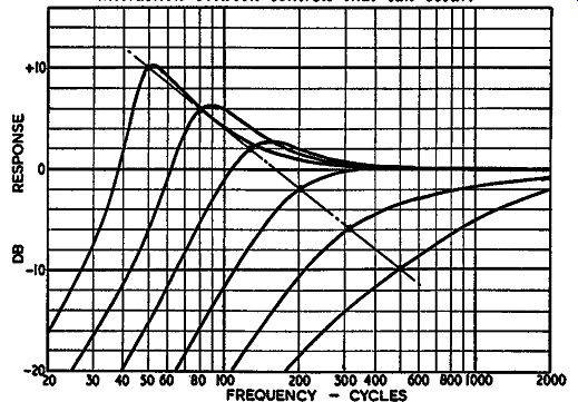
Fig. 1030. Low-frequency response variation that can be achieved by
varying the straight (non-frequency-discriminating) feedback over a two-stage
amplifier.
As transformers are little used for interstage purposes these days and the acquisition of a special type would prove difficult, this item is presented here only for the sake of completeness. It is a possible method of control that has actually been used. It illustrates the difference between this kind of control and a somewhat similar one produced by the feedback arrangement.
If the amount of feedback over a two-stage R-C-coupled amplifier is varied, the degree of peaking will alter according to the amount of feedback applied (Fig. 1030). Not only the amount of peaking but also the frequency of the peak will shift. In the case of low-frequency peaking, the effect of the feedback is to extend the frequency range farther as a greater amount of feedback is applied. This means that as the peak becomes higher its frequency becomes lower. At the top end of the range, if this method is applied, making the peak higher will also raise its frequency.
Fig. 1031 shows a circuit employing a 6AW8 using this principle for the low-frequency end. The amplification changed for feed-back purposes is the overall feedback-loop gain. This is achieved by using an internal loop that varies the forward amplification.

Fig. 1031. A circuit, using the two parts of a 6A W8 tube to achieve
the variation in response of Fig. 1030.
This inner-loop feedback is taken from the slider of the 10,000 ohm potentiometer in the plate of the pentode section, back into the grid circuit. When the slider is at the top end of the potentiometer, there is no feedback to this short loop. When it is at the bottom end, there is maximum feedback, reducing the overall gain of the amplifier before the overall loop feedback is applied.

Fig. 1032. Applying the circuit of Fig. 1031 for producing the same
kind of variation in high frequency response. 1n each of these schematics,
C1 and C2 are the controlling reactances.
The overall loop feedback will maintain the mid-band response practically constant, being essentially dependent upon the feed back factor provided by the resistors. However, the phase-shift effect will radically change the feedback toward the rolloff point, reducing the amount of feedback effective and producing a peak.
This will be varied according to the amount of overall feedback, which, in turn, is adjusted by changing the gain of the amplifier by the internal-loop feedback control.
Distortion is minimized under all conditions with this circuit because all adjustment of gain is achieved by feedback, either in the internal or external loops.
The same circuit can be applied to a high-frequency control (Fig. 1032). The difficulty is that the two cannot readily be combined because the response at each end is dependent upon the dis tribution of the feedback between the inner and outer loops purely a resistance adjustment. It cannot have two different settings at the same time, one for the high-frequency response and one for the low. The only feasible way to provide independent control of this kind at both ends of the frequency range would be to use the two circuits in cascade, requiring two tubes, one after the other.

Fig. 1033. A combination that enables low and high frequency tone control
to be combined in the same two stages, giving response variation as at
Figs. 1030 and 1001-C respectively.
An alternative which produces the same low-frequency variation but a high-frequency variation of the more normal pattern, is shown in Fig. 1033. An additional ganged control is provided across the feedback resistors to achieve variation of the high frequency according to the response shown in Fig. 1001-C. The thing to watch here, however, as in several circuits of this type, is that the high-frequency control does not interact to any appreciable degree with the low-frequency one, or vice versa. It is not usually possible to avoid interaction altogether with this kind of arrangement, but if the interaction can be minimized so that the degree of low-frequency boost, for example, does not change by more than 1 db with adjustment of the high-frequency control, this should be considered satisfactory. This kind of inter action will always occur with feedback type controls more than with the direct type.
Variable-slope rolloff
The final tone control to consider is the variable rolloff, applied particularly for getting the best out of old recordings or indifferently received program material. Two typical circuits are illustrated in Figs. 1034 and 1035.

Fig. 1034. A variable slope rolloff circuit, using a modified twin-T
and feedback to achieve the effect.

Fig. 1035. An alternative vari able slope rolloff circuit, using inductance,
mutual inductance and capacitances to produce the effect in a twin 1r
circuit.
The first uses a direct two-stage rolloff arrangement, coupled with a feedback circuit using a modified twin-T network. A twin T network gives a complete 360° phase rotation. The classic twin-T uses values which produce a null point in the middle of this rotation. This circuit is employed for straightforward null arrangement to eradicate an unwanted frequency. It can also be employed with a feedback arrangement to produce a sharply peaked response, by arranging 100% feedback over a high-gain amplifier at all frequencies except where the null occurs.
But this is a different application. The twin-T is not the "ideal" arrangement; it is deliberately "misadjusted" to produce a 360° phase rotation. We start out in the mid-range frequency with negative feedback. Then, as the two-stage rolloff starts to produce attenuation, the phase swings round through 180° to produce positive feedback which offsets this attenuation, maintaining a level response out beyond the point where the R-C elements are producing rolloff. Finally, the phase rotation continues through another 180° to produce a very rapid rolloff by reverting to negative feedback.
This is without the control components added to produce the variable slope. Variation is achieved by shunting the top limbs of the twin-T with a variable resistance and a suitable value of capacitor. This changes the rate of phase variation and also the response of the network. By careful choice of components, the overall result is that the same rolloff frequency is used but the slope is changed, producing a response family as shown in Fig. 1005.
Using different capacitor values switched into the circuit as in Fig. 1036, the variable response slope can be achieved at any of a selected number of turnover frequencies. This arrangement forms the basis of the Leak vari-slope arrangement.

Fig. 1036. The circuit of Fig. 1034 altered to provide variable slope
roll-off at three different frequencies.
The alternative method (Fig. 1035) employs a mutual-inductance-coupled filter network. The principle is the same except that, instead of using a twin-T with only resistors, capacitors and feedback to achieve the results, this circuit uses a two-stage pi filter network with additional mutual coupling to sharpen the "knee." A resistor damps the center capacitor limb of the twin pi and the other end of the same potentiometer provides additional coupling between this center point and the output of the network. The combined effect of a suitable value potentiometer that changes both these things at once is to produce a variable slope response almost identical with that given by the feedback arrangement.
An important feature of this is the degree of coupling between the two coils of the twin pi network, which has the effect of producing maximum sharpness, accentuating the rolloff point. Also, as the control is changed, it maintains a coupling in progressively reverse action to help continue the response without such a sudden drop toward the high end. This it does by providing some through coupling from the input point to the output point of the filter coils. This circuit forms the basis of the Quad vari-slope filter. Different frequencies of rolloff are again provided by changing the capacitor values in the circuit.
The question now comes as to which of these two circuits will be considered the better for the particular purpose. This is almost impossible to say because the factors which we use as a basis for discriminating between other circuits-that is, the possible distortion and dynamic range-do not apply here. The very reason for which we apply this kind of circuit says we have a poor dynamic range and conditions in which minimum distortion is un necessary in the program handled.
The combination of arrangements chosen will depend upon the application for which they are to be used. Conflicting factors in selecting an assembly are the versatility and simplicity of any control system. To make the system as versatile as possible means that the response must be variable in a number of different ways. This requires a greater number of controls. On the other hand, this kind of control can more readily result in improper adjustment and thus be misused. A simple control with one knob for the high frequencies and one knob for the low has much to recommend it, especially for those who do not know much more about frequency response than the difference between bass and treble.
So one has to make the choice of a tone-control arrangement according to the use it is expected to get: whether it will be operated by skilled personnel or by nontechnical people who just want to have good listening; also whether it will be used on comparatively high-quality program material which only requires delicate adjustment of balance, or to make the best of inferior pro gram material by getting rid of undesirable sounds.
Transistors
The foregoing variety of circuits has developed with the use of tubes as amplifiers. Now we start all over to apply similar techniques to the more recent innovation, the transistor. This prom ises to yield an even greater variety of circuitry. At the present "state of the art," the principal application of transistors in audio has been to the miniaturized portable radio and record player field. These scarcely boast of a tone control in the sense used in this section: a simple high frequency rolloff suffices.
The important thing in transistor circuits is to remember that current is the important feature. For this reason, the usual volume control or tone control arrangement used for tube circuits is reversed. In tube circuits, the input goes to the "top end" of a potentiometer, and the output is taken from the slider. This divides the voltage provided by the previous stage.
In a transistor circuit, the input goes to the slider of the potentiometer, and the output comes from the "top end." This insures that the resistance in the base circuit of the following stage does not change with setting and upset the bias. But it also divides the current provided by the previous stage, rather than the voltage. When the control is turned down, most of the current from the preceding stage (audio component) is shunted through the "bottom end" of the potentiometer, while only a small pro portion is fed through the upper part to the following emitter.
This is the volume control arrangement for a transistor amplifier. Tone control uses a variation, with suitably chosen capacitors in the circuit, so that current division, either in the forward amplification or as a feedback function, only takes place in the part of the spectrum to be controlled.
Unlike the tube circuit, in which circuit resistances are principally of importance in avoiding distortion, it is more important to maintain the circuit operating conditions in a transistor amplifier. The de resistance of both emitter and collector circuits should not be changed by the control settings. The other difference is that the circuits are designed to modify the current division of audio at different frequencies, rather than the voltage division, which is the usual parameter in designing a tube circuit.
Transistors promise to prove much more versatile than tubes.
At present only the grounded emitter circuit has been extensively applied. But other connections, and combinations of connections, hold a possibility of greater variety. So it would be impossible to present a comprehensive treatment of this application, compatible with the rest of this guide, from the information now available.
When it becomes available, it will warrant another guide in itself.