ASSUMING a satisfactory preamplifier, amplifier and various elements for the reproducing system, the main problem in achieving realism centers in the speakers. Original sounds come from all kinds of sources which may be constructed of metal, wood, string, gut or other materials. They may also be small or large. Each sound source has its own "character," and yet we expect a speaker system to reproduce different sounds with uniform fidelity.
In the various stages of amplifiers, the principal requirements are a uniform frequency response overall (at any rate when the equalization has been inserted) and freedom from distortion.
But when such an almost perfect system is fed into various speakers divergent results can be noticed.
Kinds of reproducer
For example, a speaker consisting of a diaphragm connected acoustically to a number of pipes of different size resembling organ pipes would give an extremely good rendition of organ music because the resonant effect of the pipes would tend to amplify the pipe sound. If the choice of pipe dimensions and positioning were good, such a speaker might well have an extremely flat frequency response. And yet, imagine the spoken voice over such a speaker! It would sound like a man talking inside the air-duct of an organ while you were listening outside.
Another illustration: trumpets or horns tend to project the higher frequencies in a narrow path, while the lower frequencies are spread out; the horn type of tweeter unit has a similar directional characteristic so a multiple system using a horn type tweeter can be expected to give realistic reproduction of trumpet or horn music. But it may not be so realistic when it endeavors to reproduce string music, the original sound source of which radiates from the surfaces of stringed instruments. For this purpose a speaker using a plastic diaphragm might give the most realistic reproduction, but its presentation of horn or trumpet music might be quite lacking.
An electrostatic unit also gives a characteristic tone. Because its diaphragm is metallic, it should sound particularly realistic when reproducing sounds like a cymbal clash.
It is impossible, in an orchestral recording, to separate the original components of the music coming from strings and horn type instruments and feed them to different types of speaker units, because the composite frequencies making up the tones from the different instruments overlap. For this reason we have to settle for some compromise that reproduces uniformly and realistically the sounds we want to hear.
The faculty of hearing helps
Fortunately we can be helped considerably by certain proper ties in the human faculty of hearing. While this faculty is extremely critical in telling the difference, for example, between the kind of radiation from a trumpet and that from a violin, it can also be extremely tolerant. This can be illustrated by considering what happens when a poor public-address system is used in an auditorium.
You may notice at first that the instruments-and even the human voice-reproduced over the system tend to exaggerate a few resonant frequencies. At first these may seem quite irritating, almost to the point of making the sound unintelligible.
But, by the time the program is over, you will probably have become so used to the resonances that you find little difficulty in understanding what is said.
Another illustration, a little nearer the realm of audio, is the development of sound reproduction itself. In the early days of acoustic phonographs, reproduced sounds were considered "almost lifelike." Then came electrical reproduction. This gave a "new dimension" to sound reproduction and once again it seemed extremely lifelike, compared to what we had become accustomed. This experience has been repeated many times be tween then and now, and still we are looking for greater realism.
This highlights the fact that the human faculty of hearing is at once tolerant and critical: tolerant because we can accept the sounds we listen to as realistic and critical because at the same time, we are looking for further improvement.
Big or small? Original sounds are radiated by sources of different sizes.
This is something that is difficult for one speaker to simulate uniformly well. A full orchestra has sound coming from all over the orchestra. If you listen to a program in an auditorium you have an impression of spaciousness in the sound source. On reproduced orchestra music, if a small speaker is used, all the sound comes from a relatively small round diaphragm, say 8 or 10 inches in diameter. So the sound you hear gives the impression, at best, of an orchestra as heard through an 8- or 10-inch hole in the wall.
At the same time when you listen to someone speaking in a small room or studio, the sound originates from an area much smaller than the same speaker.
While a multiple-unit speaker, with the woofer in one place, the squawker or mid-range unit in a different position and a tweeter in yet another, can provide an effectively large source for reproducing orchestral music, it still is a little unrealistic. The distribution of the component parts of the sound "pattern" is still not that obtained with the original orchestra. In the original orchestra, the different sources of sound contain overlapping frequencies: the string section of the orchestra, which may be located to the left, contains the same band of frequencies emitted by the wind section, which may be at the right.
The speaker, however, which does present a large source area, brings the lower frequencies from the woofer, the middle frequencies from the middle range unit and the higher frequencies from the tweeter, regardless of whether these originate with the string or wind section of the orchestra. So the distribution pattern is quite different.
However, it is possible to get a better sense of realism with a multiple-unit speaker (or even with more than one single-unit) than with a single relatively small speaker.
Intermodulation
The original reason for introducing multi-unit speakers-one for the low and one for the high frequencies, and later division into more than two sections, to include a mid-range unit-was not primarily connected with the matter of apparent size of source. It was for another reason-the fact that the speakers them selves introduce more distortion than most amplifiers do. This distortion is evident by the intermodulation it causes.
Reproducing just two frequencies at the same time with a non linear device will generate spurious frequencies. Program material has many more than two frequencies, so any unit in a system that possesses this form of distortion will cause many frequencies not present in the original program to appear. The most objectionable form of this occurs when low frequencies and higher frequencies are reproduced over the same channel.
A speaker diaphragm moves a considerable distance at low frequencies, hence its sensitivity to higher frequencies may change during the low frequency's excursion. This could be due to non linearity of the compliance of the spider, the surround material, or nonuniformity of the magnetic field in the airgap through which the moving coil travels. The net result is that the large amplitude low frequency modulates the high-frequency tones being reproduced at the same time.
The effect is one that may often have been noticed on ordinary reproduction: the higher frequency tones go dithery whenever there is a loud low note. So, separating the frequencies and feeding them to different speakers avoids some of this problem by presenting the low-frequency high-amplitude tones over one unit and the higher-frequency tones that might get modulated over another unit that does not receive the low frequency tone.
Integration
The next problem is one of producing an overall sound that is well integrated, particularly for the reproduction of spoken pro gram material, with a male voice in particular. It does not sound natural if the deeper, throatier components of the voice come from the woofer, the main body of speech from mid-range unit, while the sibilant sounds get squirted from the tweeter in yet another direction. The three sources of sound should be blended together to give the impression of a single unit source. The coaxial and triaxial type units are the better forms of multi-unit speaker for achieving this objective.
More than one speaker
Because of the conflicting requirements for one speaker, some prefer to use more than one, selecting different types. In this way, by suitable adjustment of balance between the units, each kind of program material can be reproduced with a compromise real ism so the overall effect is better.
If the levels are reasonably well matched, the tolerant capacity of the ear helps considerably by psychologically associating voice production and solo program material with the well-integrated speaker and the wide-spread sources of sound with the multi-unit variety. This, of course, can happen only if the levels are right so the ear can hear both units at once.
Because speakers differ in sensitivities, it will often not be sufficient just to connect the two units in series or in parallel, al though they may have the same impedance. Two 16-ohm units, in parallel, can be applied to the 8-ohm output of an amplifier.
But this may result in one sounding considerably louder than the other, although both receive the same amount of power. This is because one unit is more efficient than the other.
To overcome this, the best plan is to insert some resistance in series with the unit which sounds louder. It will require only a few ohms-say 4 or 5-to balance things. Use a 20-ohm wirewound potentiometer connected in series with the speaker which reproduces the loudest (Fig. 801) and adjust for the most pleasant balance of reproduction of various kinds of program material, as judged sitting in the room at an approximately equal distance from both speakers.
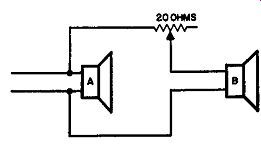
Fig. 801. If speaker B is more sensitive than A. the two can be matched
by a series resistance.
The effect of series resistance will deteriorate the damping of that speaker which is of special value in the low frequency resonance region (40-130 Hz, according to individual type). A resistance of 4 ohms in series with a 16 ohm speaker limits the damping factor to 4, even if the amplifier has infinite damping. If the speaker needs better damping than this, dual operation is not possible without a compromise. However, the effect of the extra speaker will probably offset the loss in performance in the one unit.
Try reversing the connections of one units and select the connection which gives the best realism-not a sense of "sound in a vacuum." This will be correct phasing.
This works out nicely if both units use an impedance of 16 ohms, or maybe even higher, so they will match conventional amplifier output impedances by being connected in parallel.
Sometimes, however, the speaker units may not use convenient impedances. For example, if the speaker impedances are each 2 ohms and the amplifier matches to 4 ohms and higher, it is obviously necessary to connect the units in series to provide a satisfactory match.
From an ideal standpoint, this is not as good as the parallel method. When speakers are connected in parallel across an amplifier output with a high damping factor, each is being fed from a low source resistance or a virtually constant voltage. On the other hand, when speakers are connected in series to an amplifier with a high damping factor, the combination of two units gets the constant voltage. Because of the individual impedance characteristics of the units the frequency response delivered to the respective units will not be the same as it was with parallel connections.
Series operation also means that each unit can, at best, be operated with a damping factor of 1, and the source resistance it sees is far from a resistance. So even more queer things can happen to damping than by inserting a resistance in series with one speaker. But, again, the advantage of having two units may still outweigh this detrimental effect in overall performance.
Occasionally the series method may sound more pleasing than the parallel connection, due to some coincidence in the relation ship between their respective frequency and impedance responses.
But it is more likely to result in inferior reproduction although in practice that may not be readily noticeable. If the series method is the only convenient method of connection, certainly don't refrain from trying it merely because in theory it is not the right one. Results may be quite acceptable and will almost certainly be superior to the use of only one speaker.
If the speakers differ in impedance and sensitivity try one of the arrangements shown in Fig. 802 for a satisfactory balance. Select the arrangement that comes closest to giving correct balance, then use a shunt or series resistance with the most sensitive unit to get the final best balance. (See Fig. 803). For stereophonic systems it is desirable to use identical speaker systems on each channel. When different speaker systems are connected to the same channel best results are often obtained by using different kinds of unit. Thus the exact response characteristic from the two is slightly different. While this is not a fully correct method of reproduction because it cannot hope to simulate the original sound, it can give a much more satisfying illusion than a single speaker-one that is often not too much inferior to a full stereophonic presentation.
Multiple-unit speakers
When considering a single-speaker system that uses two or more units, an important consideration is the crossover frequency at which transition is made from one unit to another.
The woofer will have to handle all the bass or lower frequencies, right down to the bottom of the audio spectrum. How high, then, should we go in frequency before we change over to a midrange unit? The principal thing here is to choose a frequency such that the excursion required of the mid-range unit is never large enough for it to cause serious intermodulation distortion, where the mid-range unit is of the cone type, the frequency is usually not very critical and any convenient value between 400 and 1,000 Hz may suit.

Fig. 802. If two speakers differ in voice-coil impedance, connect them
in parallel (a) or series (b) for the nearest to correct balance in volume
level.
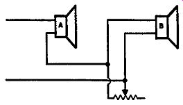
Fig. 803. If the series arrangement of Fig. 802·b is preferable, the
job can be finished by an adjustable resistor in parallel with the more
sensitive unit B. If the parallel connection is best. use a series resistor
(see Fig. 801).
Where the mid-range unit uses a horn type speaker-commonly called a squawker-the frequency is a little more critical. Any at tempt to produce frequencies below the cutoff designed for the horn will result in excessive excursion of the voice coil in the drive unit, causing distortion. So the crossover frequency should be above the low-frequency cutoff for the type of horn used. This is usually stated in the manufacturer's literature.
While some use a small-diameter cone for the tweeter, the much more common practice is to use either a horn or an electro static unit for the extreme high end. Where the cone type is used, the crossover frequency is not very critical. But for the horn type unit we again have the question of the cutoff frequency.
Where an electrostatic unit is used, the matching arrangements are a little more critical. The electrostatic unit requires a high polarizing voltage; and also a high-impedance feed from the amplifier rather than the low-impedance feed used for the other unit. The instructions provided with the electrostatic tweeter are the best to follow for a good match.
Modem high quality electrostatic units come complete with a built-in matching transformer whose primary has a nominal impedance similar to most amplifier outputs. But this does not alter the fundamental situation. A transformer cannot transform a capacitance into a resistive impedance. It merely transforms the capacitance to a different value, suitable for applying across the low impedance circuit. In this case the nominal impedance is chosen by the speaker unit manufacturer so that, with an amplifier of average damping factor, the high frequency response is satisfactory, and the sensitivity comparable with that of an aver age dynamic unit.
These are conflicting requirements for the electrostatic unit to meet. At the nominal impedance for the Janszen unit, the amplifier must have a damping factor of at least 2 to avoid high frequency rolloff. This could be achieved by connecting the electro static matching transformer to a tapping on the amplifier lower than its nominal rating, if the damping factor on the rated tapping is too low, but this will degrade the sensitivity of the tweeter compared to the other units.
Peaky highs
An important point to watch for is the possibility of high-frequency peaking introduced by the use of an electrostatic unit.
This should also be watched for with any other kind of tweeter.
This effect can be due to poor tweeter design, but often it arises from the peculiar characteristics of individual amplifiers. Do not confuse this effect with the high rolloff due to inadequate damping factor. Actually both can happen in the same amplifier, which is an extremely undesirable effect. The condition we are now talking about is due to a characteristic of the amplifier, rather than to the method of feeding the speaker in question.
These amplifiers have been designed to give a flat frequency response and satisfactory square-wave or transient reproduction, when feeding a resistance load. The usual high-frequency tweeter provides an inductive load at the high-frequency end due to the voice coil inductance, while the electrostatic tweeter provides a definitely capacitive load. In various amplifiers one or the other of these may tend to produce high-frequency peaking, due to the phase shift it introduces in the overall feedback loop. The choice of circuit should be chosen with a view to avoiding this trouble.
This is covered in the section on feedback. Otherwise the only thing to do is to try different amplifiers to find one that gives satisfactory performance into the chosen loudspeaker combination.
Balance
Not only is it necessary to divide the frequencies correctly, but also to maintain correct balance in the reproduction. A well designed crossover will ensure that uniform energy is fed to one or other of the speakers throughout the frequency band. But if, for example, the squawker and tweeter, because they are of the horn variety, are more efficient than the woofer, then the arrangement will seem to be bass-weak because the woofer does not de liver as much sound energy for the same input as the other units.
To get a flat overall response, the mid-range and tweeter units will require attenuation by the insertion of one of the small L pads available for this purpose.
A simple series resistance, as suggested for balancing wide-range speakers, is not adequate here because it will cause mismatching to the crossover unit. A speaker of 8 ohms, for example, with a resistance of 4 ohms in series, makes a total resistance of 12 ohms.
This would compensate for a 2-db difference in sensitivity-it may be necessary to do even more than this. If the crossover is designed for 8 ohms, then there will be considerable mismatch resulting in a distortion of the frequency response in the region of crossover, apart from the question of obtaining uniform level in the main part of the band. For this reason an L-pad of the correct resist ance to go with the particular speakers being used should be inserted. In fact it is good to have two in a three-way system; one for the mid-range unit and one for the tweeter.

Fig. 804. A properly designed L-pad maintains the correct resistance
to load the crossover by varying R1 and R2 at the same time. The resultant
value is always the same as that of the voice coil alone.
The L-pad maintains matching by using series and shunt resistors at the same time, so the resistance "reflected" to the cross over is always correct (Fig. 804). In making these checks, phasing is also important. Try connecting the units in alternate ways to make sure you have the connection that gives best realism. Reversal of one unit in a multiple unit system spoils realism.
Kind of crossover
In deciding on the kind of crossover to use, determine how sharp the transition should be from one unit to the other, and how many db per octave rolloff is needed in each unit. This is a matter about which there is some difference of opinion. The answer depends to some extent on the type of unit used.
Where individual speakers have considerable deviation from level, there will also be fluctuating phase angles. Hence it is good to effect as sharp a transition from one unit to the other as possible to avoid an even more erratic response from the combination. But where each unit gives a smooth frequency response in the region of transition, such a sharp crossover is unnecessary.
In fact it is better to have a more gradual transition so as to avoid some of the difficulties that can arise with the sharper unit.
There are two ways of designing a crossover network. One uses filter theory; the other is based upon what is termed the constant-resistance technique. The latter is preferred because it delivers constant energy to the combined speakers and at the same time provides a constant resistance load for the amplifier, assuming that the impedances of the individual units are resistive.
In practice, of course, this does not happen because there is always some reactance in the impedance of the speaker. But the use of the constant-resistance type results in less error due to the presence of these reactances than does the filter type crossover.
Fig. 805 gives the relative reactance values at the crossover frequency for constant-resistance networks employing one, two or three reactances in the feed to each speaker. With the aid of a reactance chart, the correct values of inductance and capacitance for each crossover frequency can readily be calculated, having decided on the configuration of crossover to use.
Inductors and capacitors
From the viewpoint of the electrical circuit constants, the next question is what kind of components to use. Should the coils be air-cored, iron-cored, ferrite or toroidal variety? And should the capacitors be paper or will electrolytics do?
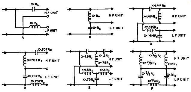
Fig. 805. Circuits using constant-resistance design values. The reactances
indicated are for the crossover frequency, in terms of the working impedance
(usually that of the voice coils) of the crossover. Input is from the
amplifier.
There are many factors to consider in making this decision.
Many will recommend the use of air-cored inductors and paper capacitors, on the theory that these are the only components that cannot introduce any distortion.
However, air-cored coils, especially for the lower crossover frequencies, are extremely inefficient. Their Q is low, hence a pro portion of the energy that should be fed to the speaker will be ex pended in the coils. It may also degenerate the efficiency of the crossover as a frequency separating device. The deficiency in energy transfer is probably the more serious one because the low frequency unit needs to operate at maximum efficiency. If the crossover loses additional efficiency for the low-frequency unit, this means still further attenuation in the other units to obtain a level response and a larger power output from the amplifier to over come these various losses.
For the low-frequency crossover, an iron-cored inductor, using laminations with an air gap (quite a small one for the lower frequencies), gives the highest efficiency. Its distortion, if correctly designed, is extremely low-lower than that due to other components in a system, as a rule.
The use of some kind of toroid inductor, provided the frequency is not too low, (where toroids become quite inefficient too) is also quite good. These inductors have inherently less distortion than the iron-cored variety although they tend to be some what more expensive.
For the capacitor elements, paper tubular or oil-filled types, ac cording to value required, are undoubtedly the best. Once the correct value has been secured, they are not likely to change value with age. But for low impedances the capacitance values are large, 6 or 8 µf qeing quite common and sometimes even 30 µf or more may be necessary at some points in the circuit. A paper oil-filled capacitor for these values would be physically large and also quite expensive.
It is much easier to obtain electrolytic capacitors in these values. As far as behaving like capacitors, they are quite satisfactory.
If the values are right, they will perform as successfully in cross over filters as any other capacitor.
The difficulty is that electrolytic capacitors can change their values considerably with time as well as deviating widely from nominal values when first purchased. If a capacitance bridge is available, it is possible, initially at any rate, to obtain the correct values by selection. Pick out capacitors that suit or make them up by paralleling a number of them, until the correct values are obtained.
Electrolytics are originally formed by application of the nominal working voltage until the necessary film is produced on the surface of the active "plate" of the capacitor. The thickness of this film depends upon the composition of the electrolyte and on the forming voltage used.
When electrolytics are stored, the electrolyte film tends to thin down, increasing the capacitance and reducing--its working voltage. When such a capacitor is placed into service, it should be re formed by applying the working voltage through a fairly large resistance to limit the polarizing current that flows through it until the film has returned to its normal thickness. Then it can be placed into the circuit with the polarizing voltage applied without fear of a surge current either destroying the capacitor or blowing a fuse in the circuit.
But when these capacitors are used in a crossover network, there is no polarizing voltage. Consequently the film tends to deteriorate anyway. This will result, usually, in an increase in the working capacitance. Electrolytics also tend to dry out, unless they are of the hermetically sealed variety, and the drying out tends to have an opposite effect, reducing the overall capacitance.
This is the serious reason for using better types of capacitor, if at all possible. When various kinds of crossovers are considered, the reasons become a little more conflicting. For the simple types using only one capacitor the value is not so critical and thus an electrolytic might be acceptable, but for the more complicated crossovers using two or three capacitors the values are much more critical. Here is where it would be a bigger saving to use electrolytics.
The best solution is either to operate the crossover at an impedance such that paper capacitors can more conveniently be used, with matching transformers following the crossover, or else to settle for a simpler. crossover. Fig. 806 shows the arrangement using matching transformers and designing the crossover at line impedance. It is probable that the saving here on the cost of the capacitors, if paper capacitors were used in either case, more than pays for the extra cost of the matching transformers.
Matching transformers of this type are usually of high-quality design, so the distortion will be negligible, especially feeding from an amplifier with high damping factor. The insertion loss will be less than 1 db (more than 80% power efficiency), and will be the same for each unit.
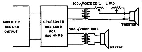
Fig. 806. For the more complicated crossovers, operate the crossover
at line impedance with matching transformers to the individual units.
A two-way system is shown here, but the same method can be used for three-way.
Channel separators
Another kind of separation used for feeding a multi-unit speaker system employs what are called channel separators ahead of the power amplifiers; that is, immediately following the pre amplification. One reason for this is that some intermodulation can occur in the amplifiers. Usually, however, the magnitude of intermodulation in a well-designed amplifier is much below any other source of intermodulation and, in fact, well below that produced in the average ear! At the same time, however, some amplifiers with very good intermodulation specifications and that show up well on test give serious intermodulation on some transient signals. This reinforces the reasons for using channel separation before the power amplifiers, although the magnitude of the effect observed is usually quite different from that present in theory.
Another theoretical advantage is sometimes claimed for separate amplifiers. This is that three 15-watt amplifiers can handle a bigger equivalent composite signal than their total rating of 45 watts.
This can be derived from a consideration of the theoretical peak power performance of the amplifiers The peak power of a single sinusoidal wave with an rms value of 15 watts would be 30 watts. If we have three separate frequencies, one in each band, so that one gets amplified by each amplifier (each of which has an rms value of 15 watts) each will have a peak amplitude corresponding to 30 watts in its own amplifier.
The total peak amplitude of the voltage amplified will be three times the amplitude of any one. Trebling the amplitude is equivalent to multiplying the power by 9, so the effective peak power presented to the loudspeaker system is not 3 times 30, or 90 watts, but 9 times 30, or 270 watts.
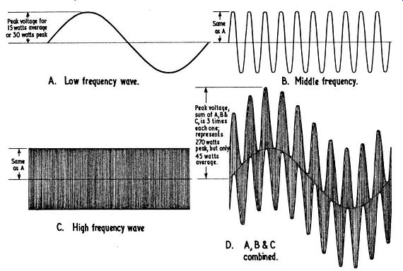
Fig. 807. Some "theoretical" waveforms associated with use
of channel separators.
A. Low freq
C. High frequency.
B . Mid-freq.
To handle this peak power a single amplifier would need an rms rating of 135 watts, instead of the supposed total of 45 watts.
Thus the argument goes that three separate channel amplifiers, rated at 15 watts each, can handle as much power as a single 135 watt amplifier (Fig. 807). This reads well in theory, but not many practical programs contain one sinusoidal tone in each of the frequency bands, each of equal amplitude. More often there will be two or three tones of equal power in the same band and only relatively small powers elsewhere, particularly in the range delivered to the tweeter. So this argument losses much of its validity when we think about practical program signals. Most of the power should be provided to handle the low and middle frequencies.
Another argument for separate channel amplifiers is that it avoids allowing the speaker impedance characteristics to interfere with the crossover accuracy by using only R and C elements in the separator and feeding the speakers from well-controlled individual amplifiers. This is true, but it is also possible to include the speaker reactance elements in the crossover elements of Fig. 805 and thus avoid this disturbance, where it proves critical.
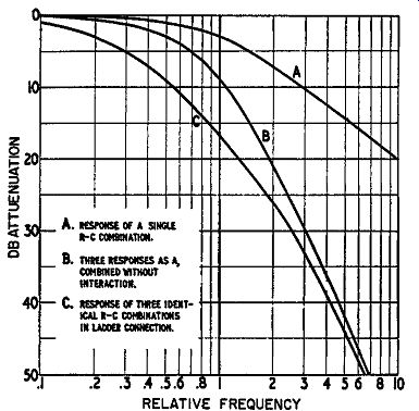
Fig. 808. Effect of ladder connection of R-C components. A is the response
of a single R-C combination. B is the addition of three responses as
at A, which would be produced by three responses A· in cascade. C is
the response produced by three identical R-C combinations in ladder connection.
It differs from B due to interaction between components.
Although it would seem that the best approach would be to get a better power amplifier and not bother with the separation before it, this is still a matter of individual preference because of the number of factors involved.
Because of the relatively low levels involved, about 1 volt at high impedance, it is not practical to use the same type of cross over used for the speakers, because inductances will prove susceptible to picking up hum. They can be shielded, of course, but this will make the unit quite expensive.
As most people who prefer this type of circuit are purists who desire to eliminate any possible cause of distortion, this is another reason for avoiding inductances-although they would not necessarily introduce an audible component of distortion, if well designed.
This leaves us with a variety of resistance-capacitance circuits.
These fall into two groups: those with feedback and those with out.
R-C circuits without feedback produce an additive effect similar to a number of separate rolloffs combined. The rolloffs can be spread so that the effect does not occur at the same frequency, but the maximum effect can be achieved by using a number of resistance-capacitance combinations that produce a rolloff at the same frequency.
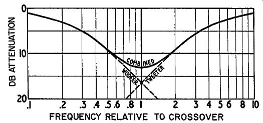
Fig. 809. Combining high-pass and low-pass three-stage ladders, using
identical R's and C's throughout, produces a "hole" in the
com6ined response.
If the R-C values of a ladder network are identical, then the effect of the successive components interact to "spread" the roll off characteristic anyway. As a result the mid-point-of the characteristic, where the phase shift is half the ultimate, will be accompanied by more than the usual combined attenuation (Fig. 808).
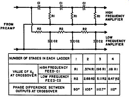
Fig. 810. Design data for ladder networks to give approximately constant
power.
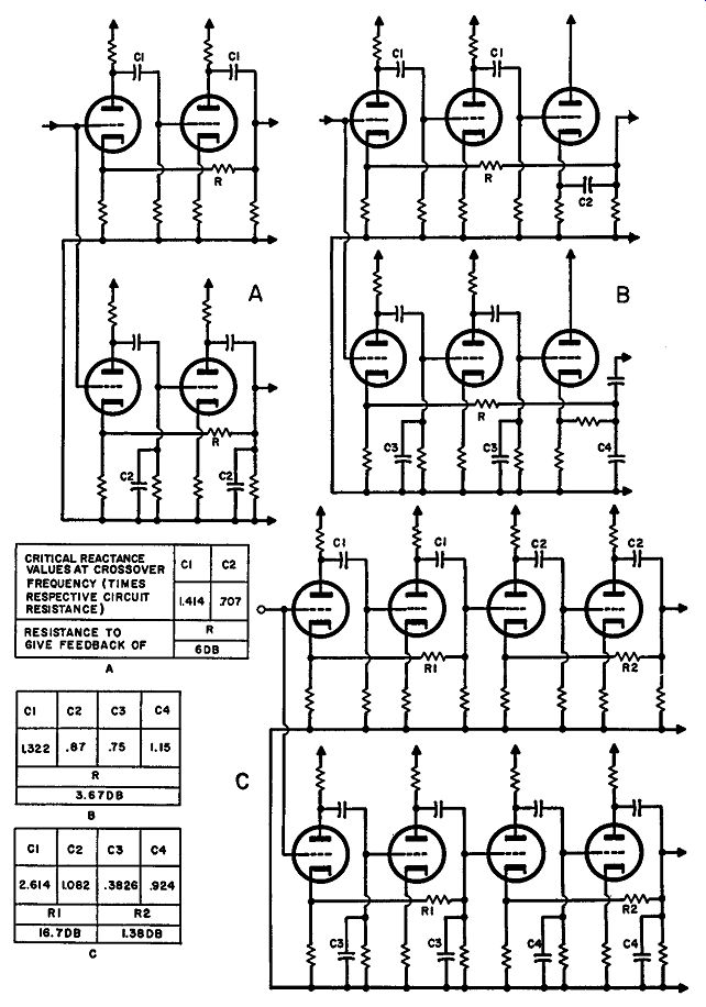
Fig. 811. Basic circuits for feedback channel separators. Only critical
values are shown. Values are given in each case relative to the circuit
in which the component is connected. Circuits include no precaution for
ensuring minimum distortion, or optimum dynamic range. These must, of
course, be taken into account when designing a practical circuit. All
that is shown here is intended to illustrate the critical components
for obtaining the right frequency response (a) 12 db/octave, (b) 18 db/octave
and (c) 24 db/octave.
For example, a network using three resistors and three capacitors produces an ultimate phase shift of 270° and a midway phase shift of 135°. The loss at the midway frequency due to separate non-interacting networks would be 3 times 3 db, or 9 db. But with a corresponding interacting ladder the loss will be 17 db at this point, although the phase shift is still 135°. This is 8 db more than the 9 db that would be provided by combining three separate rolloffs at the same frequency.
This means that making the rolloffs at the same frequency for both high- and low-pass sections of the filter, i.e. using identical R's and C's throughout, will produce a 14-db dip in the response.
(Fig. 809). This can be remedied by "sliding" the design frequencies for the two sections together to produce a 3-db loss in each at the crossover frequency. This will give the same total energy at crossover frequency as is delivered to each unit at frequencies remote from crossover.
When this is done, the circuit achieves very close to the constant-resistance requirement, although there is some phase difference in the region of crossover frequency that is not normal to a constant-resistance arrangement. However, the ultimate rolloff slope is not reached until a long way beyond the crossover frequency. The slope at crossover is very approximately 3 db per octave and at one octave beyond crossover it has reached the region of 4.8 db per octave and an attenuation of about 7 db-regard less of how many stages are used (Fig. 810). Feedback separators If a sharper slope is required beyond crossover, the only way to achieve this with R-C components is to use a feedback type of crossover. This uses feedback to accentuate the rolloff produced by the individual components. Responses can be achieved that are identical with any of the constant-resistance crossover types, both in phase and attenuation characteristics. Basic circuits and parameters are shown in Fig. 811.
They have the advantage over crossovers in the power output in that they are not susceptible to the reactance loading of the speaker, which reflects only on the output of the amplifier and does not influence the performance of the crossover.
However, to offset this advantage, there is the disadvantage discussed in the previous section, relative to equalizers, that they are much more critical of tube parameters in the section of the amplifier over which the feedback is applied. Change in the gain of a tube will change the sharpness of the crossover, the phase shift and attenuation characteristic, by at least as much as loading with a speaker, that contains a reactance, will modify the characteristic of a constant-resistance crossover in the output.