IN many respects the picture tube is the most important component in the TV receiver. It is, in most cases, the most expensive single unit in the chassis and requires a greater number of adjustments than any other component. Improper adjustment can irreparably damage it. Improper handling of the tube can land the technician in the hospital or burn or shock him. Incorrect diagnosis can lose customers. Insufficient knowledge of the picture tube and its associated circuits can cause the technician to spend an excessive amount of time in locating or eliminating trouble.
There are many reasons, in short, why the service technician should know all there is to know about the adjustment, servicing and replacement of cathode-ray tubes. Some theory must inevitably enter into our treatment since it makes for more enlightened servicing; it will, however, be kept to a minimum.
Numbering system
A certain amount of important information is provided by the code number assigned to a cathode-ray tube. Actually, this is not simply a number. It is, rather, a grouping of numbers and letters.
This grouping may be broken into three or four parts. The first consists of a one- or two-number digit and precedes the first letter. The number is the size designation of the tube and indicates the nominal diameter of the faceplate in inches. (In the case of a rectangular tube, the first code unit indicates the length of the diagonal--i.e., the distance from one corner of the tube to the opposite corner). If the tube is a 30BP4, the coding tells us that the tube's diameter is approximately 30 inches.
The next part of the code is the first letter. In the case of the 30BP4 just referred to, this letter is B. The first letter has a purely historical significance. It indicates when the tube type represented by the picture tube in question was registered with RETMA.1 The letter A is given to the first tube type of a given size registered with RETMA; B is the second, C the third, etc. In the case of the 30BP4, the B indicates that this tube type was the second in the 30-inch series to be developed.
The fact that there is no 30AP4 may seem odd. Why was a B assigned when no A had apparently been released? The answer lies in the fact that letters are reserved with RETMA before a tube type is actually registered. In many cases, the particular tube the manufacturer had in mind never reaches the production lines.
The reserved letter is thus never used.
The third coding unit consists of the letter P followed by a number. The P stands for the word phosphor. The number following the P indicates the kind of phosphor used for the screen.
In the case of black-and-white TV tubes the third coding unit is P4.
It refers to all-silicate, all-sulfide, and silicate-sulfide type phosphors that have the persistence and color characteristics needed for the proper reproduction of television images. Picture tubes used for purposes other than TV image reproduction have different phosphor designations.
A fourth coding unit sometimes present consists of a letter. It is known as the modification letter. Such a letter is added to the code number of a tube when a minor design change is made in the tube by the manufacturer some time after its initial appearance.
The change may be a purely physical one: a different kind of glass, for instance, may have been substituted for that originally used as the faceplate. Or it may be an electrical change- say, the addition of an Aquadag coating to the bell of the tube or an alteration in the basing connections. When the letter A is used as the modification letter, it often indicates a switch from a clear to a gray Filterglass faceplate. When the letter B has replaced the letter A, a further change from the gray Filterglass faceplate to a frosted one is indicated. In any case, the manufacturer's data should be consulted for information regarding the exact nature of the change before a modified tube is substituted for the original.
Bulb and base differences
[Now known as Electronic Industries Association (EIA).]
Cathode-ray tubes may differ from each other physically and/or electrically. They are made in many different sizes and shapes and can be constructed of different materials. They may have different deflection and focusing systems, gun structures and external accessories. These differences all have a bearing on servicing.
Round vs. rectangular tubes
The advantage of a rectangular-faced picture tube over a round faced one is that it permits a larger picture to be shown on roughly the same-size screen. It also requires less cabinet space and weighs less. A round-faced tube, on the other hand, is stronger. Many of the larger-size picture tubes are being manufactured with round faceplates for this reason.
Aquadag coating
To collect the electrons emitted from the screen and return them through the power supply to the picture-tube cathode, a conductive coating commonly known as the Aquadag is placed on the inside surface of the bell in the all-glass tube. This internal coating starts about 2 inches behind the faceplate and extends partly down the neck of the tube in most cases. Internally connected to the high-voltage second-anode contact, it is considered part of the second anode where a second-anode cylinder is used in the electron gun. When such a cylinder is absent, the internal Aquadag in itself comprises the second anode.
Strictly speaking, Aquadag is not necessarily the correct name for the cathode-ray tube's internal conductive coating. Aquadag is the trade name of one of the several compounds (such as graphite, lead sulphide, etc.) used to form this coating, but the industry uses the term as practically synonymous with the conductive coating.
In most picture tubes, an external as well as internal Aquadag coating is used. The external coating covers the outer surface of the bell of the tube, to a greater or lesser extent, but does not make contact with the anode connection on the tube envelope. It is usually separated from this connection by a circular section of clear, uncoated glass.
The internal and external Aquadag coatings form a capacitor with the glass between serving as the dielectric. This capacitor is used as part of the high-voltage power-supply filter network'. The actual capacitance present depends (up to a point) on the size of the tube. In the 3N P4, for instance, the minimum capacitance is 275 uuF; the maximum is 375. In the case of a 24VP4, the minimum capacitance is 750 uuF; the maximum 1,500. Minimum and maximum limits set the extremes allowed by manufacturing tolerances.
On most of the larger-sized picture tubes, the external Aquadag covers a lesser portion of the exterior bell area than it does on somewhat smaller tubes. For instance, the outer Aquadag covers most of the bell area on a GE-type 17BP4-A; the outer Aquadag, however, covers only a 2-inch section (approximately) on GE's 21EP4-B. The reason for this may be explained as follows: A relatively large capacitance, fed from a high second-anode potential, could store a large enough charge to constitute a safety hazard.
Any service technician who has been jolted by 2,000-volt .001-pf capacitors in early-make TV sets using transformer-type high voltage power supplies will readily appreciate this point. Since the larger tube uses higher second-anode potentials, the capacitance formed by its Aquadag coatings must be kept down to minimize the shock potential of this capacitance.
When a glass tube that has no external Aquadag, or a metal tube, is used to replace a glass picture tube with an external Aquadag, a capacitor of about 1,000 if should be connected be tween the second-anode point of the high-voltage supply and ground to compensate for the absent capacitance. The compensation will be only partial (but generally adequate) in the case of a tube like the 16HP4, which has a maximum capacitance between its bulb coatings of 3,500 uuF.
When an external Aquadag coating is used to form a capacitor with the internal coating, some means of grounding the external coating must be employed to make the capacitance effective in the circuit. Metal clips, bands or spring type wires are used for this purpose (see Fig. 701). If these connectors do not provide good contact between the external Aquadag and chassis, a variety of symptoms may be introduced. The external Aquadag acts as a shield for the picture tube in addition to forming part of a filter capacitor. If it does not connect properly to ground, however, its shielding (as well as its filtering) action is impaired. Various interference effects (as well as corona and arcing) become possible.
The external Aquadag may, furthermore, be at high-voltage potential with respect to chassis if it isn't grounded. The reason for this is that the charge on the inner coating is transferred to the outer one through the stress set up in the glass dielectric between them. Shock may be experienced when the technician touches the tube.
Glass vs. metal tubes
Cathode-ray tubes are made with all-glass envelopes or envelopes composed partly of metal, partly of glass. Tubes in the latter category are known as metal tubes and can have rectangular or round faceplates. Metal is used only for the bell section of the tube.
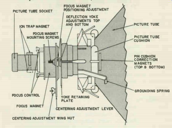
Fig. 701. Components mounted on the neck of the picture tube. The grounding
spring connects the outer Aquadag coating to the chassis.
An envelope made partly of metal has greater strength than an all-glass one. The risk of an implosion is thus reduced. An additional advantage of the metal tube lies in the shielding effect it provides. External electromagnetic fields-such as those surrounding power transformers, etc.-are prevented from affecting the electron beam within the tube. A third advantage lies in the fact that it can be made of a lighter glass than an all-glass unit, permitting its weight to be less.
Disadvantages of a metal type tube include the fact that it introduces a considerably greater shock hazard than an all-glass tube. Part of the inner surface of the bell must be at high-voltage potential to collect the electrons emitted by the fluorescent screen.
Since no insulation between the inner and outer metal surfaces of a metal tube is practical, both surfaces are at the same high potential. To protect the service technician against shock, plastic insulating covers may be placed over the metal cone area when tests must be made with the power on. These covers, unfortunately, offer little or no protection against rf burns. An unsuspected source of shock may be created by leakage of high voltage from the metal cone to the deflection yoke, metal cabinet or other components.
In an all-glass tube, the inner and outer Aquadag coatings form a capacitor with the glass between acting as the dielectric. The metal tube is, of course, incapable of providing a similar capacitance. A separate high-voltage filter capacitor must therefore be added to the high-voltage power supply when a metal tube is used to replace an all-glass type.
Still another disadvantage of the metal tube lies in the susceptibility of the metal cone to magnetization. While the cone shields the electron beam from stray magnetic fields, it may itself become magnetized when the fields are too strong and too close. In some cases, the metal shell can be demagnetized by the TV technician.
In others, demagnetization attempts can produce incomplete and unsatisfactory results.
The faceplate
The term faceplate refers to the large-ended surface of the cathode-ray tube. The fluorescent screen is coated on the inner side of this surface; the outer transparent surface permits viewing of the picture reproduced on the inside of the faceplate.
The faceplate is curved or spherical rather than flat to permit uniformly satisfactory focus over its entire area. A curved faceplate reflects external light more than a flat one would; furthermore, light passing through the faceplate is refracted or distorted. The greater the curvature of the faceplate, the more troublesome do these effects become. Faceplate curvature is described in terms of the radius of the semicircle formed by the faceplate. The shorter the radius, the greater the curvature.
To minimize the undesired faceplate characteristics introduced by curvature, cylindrical shapes are employed in some tubes. Such faceplates can be used only in rectangular tubes. When a cylindrical faceplate is employed, advantage is taken of the fact that the picture height is less than the width; the curvature required for good focusing is consequently smaller from top to bottom of the picture than it is from side to side. The faceplate is constructed accordingly. The reduction in top to bottom curvature decreases undesired reflection and refraction appreciably.
Faceplates may be of clear glass, gray glass, Filterglass, or frosted Filterglass (also referred to as etched face). Clear glass permits the passage of the greatest percentage of light from the inner to the outer surface of the faceplate. A loss in contrast is produced, however, by reflection from the faceplate of external lights. These losses become rather serious in tubes with large-sized faceplates.
To minimize these losses, gray or frosted glass is used in most picture tubes manufactured at the present time. The reduction in the picture-tube light-transmission characteristic is more than compensated for by the decrease in reflections. It is worth noting that all cylindrical-faced tubes use Filterglass.
Faceplates range in size from the 3NP4 with a nominal diameter of 3 inches [2] to the 30BP4 whose nominal diameter is 30 inches. [2. Cathode-ray tubes haying smaller face diameters do exist. The IEP1 has a diameter of only 1.25 inches, is designed for lightweight portable equipment. The IEP1 uses electrostatic focus and deflection.]
The term nominal merits some explanation. Nominal means in name only. When used in relation to picture tube sizes, it means approximate. The actual diameter or diagonal is different from the nominal one given in the code number. Thus a 27EP4-a rectangular tube-has a nominal diagonal of 27 inches but an actual diagonal of 26-13/16 inches ± 3/16 inch. Some manufacturers may, in such a case, refer to the number 26-13/16 as being the nominal diagonal of the tube, whereas the actual one falls somewhere between 26-13/16 4- 3/16, and 26-13/16 - 3/16. The ± 3/16 inch is, of course, the tolerance.
In some cases where a picture tube is being replaced, it may be desirable for the service technician to know the exact dimensions of the replacement tube to determine whether it will fit the opening in the cabinet. It will be helpful in such cases to obtain the manufacturer's specifications (from his tube data sheets). The manufacturer is allowed certain tolerances since tubes cannot always be made according to exact design size. This tolerance, as specified by the manufacturer, should be taken into account when the exact dimensions are important.
Another term with which the service technician may be concerned is the useful screen size as opposed to the nominal or actual size of the picture tube. The useful screen size is the maximum faceplate area within which a picture may be seen. Masking considerations may make it necessary in some cases to know this size.
Picture-tube lengths
Tubes vary considerably in length. Electrostatically deflected units are longer than magnetically deflected ones with the same size faceplates since deflection plates must be accommodated inside the electrostatic type. Magnetically deflected tubes with the same size faceplates may have different lengths. In general, the larger the deflection angle, the shorter the tube length for a given-size faceplate.
Tubes that have the same deflection angle, approximately the same size faceplate and are pretty much alike electrically may differ appreciably in length. It is thus important to know the tube length of a replacement picture tube when it is not identical with the original. Relatively slight differences in length may prevent the proposed replacement from fitting readily into the cabinet.
Tube length specs are provided in bulletins and data sheets put out by picture-tube manufacturers.
The screen
The inner side of the faceplate is coated with a phosphor material which acts as the screen of the picture tube. The picture is reproduced on it and viewed from the outer side of the faceplate.
The screen contains both fluorescent and phosphorescent materials. It fluoresces when electrons strike it-that is, it emits light.
The property it has of continuing to emit light when the electron bombardment has ceased is known as phosphorescence.
The phosphor coat has two important characteristics, as far as the service technician is concerned: persistence and color. Persistence refers to the length of time the phosphor continues to emit light after the electron bombardment responsible for the light emission has ended. This time is characterized as extremely short, very short, short, medium, long or very long.
TV picture tubes use phosphors with a medium persistence. A screen with too long a persistence tends to cause blurring of rapid motion.
Screens vary in the color of light they emit. Phosphors used most often emit white light since this is the kind of light that produces maximum contrast and is least tiresome to view for long periods of time. Picture tubes used for TV receivers employ a P4 phosphor for their screen coating; this phosphor has a medium persistence and provides a white light.
Aluminized screens In some picture tubes, a thin layer of aluminum is added to the phosphor coating on the screen. The aluminum film is also applied to a portion of the inside surface of the bell of the tube.
It connects to the second anode terminal on the picture tube.
The aluminum layer is intended to increase picture brightness and reduce the risk of ion damage to the screen. The increase in brightness is the result of decreased light losses in the aluminized tube. In a tube with a non-aluminized screen, a high percentage of the screen light output is lost due to the absorption of light by, as well as its random reflection from, the Aquadag coating on the bell of the tube (or from the inside metal surface of a metal type tube). In the aluminized tube, part of the internal Aquadag coating is replaced by an aluminum film. The aluminum film also overlays the phosphor on the faceplate. Light that would other wise be absorbed or reflected toward the rear of the tube is now reflected toward the screen face and remains useful. Brightness is thus considerably increased.
The service technician can get an idea of the increase in bright ness by making the following visual test: Look through the tube section that lies between the faceplate and the area where the internal Aquadag begins in a conventional glass picture tube of a certain size. Note the brightness of the picture. Next, look into the same section of an aluminized picture tube of the same size (it is assumed that the TV receiver in each case has approximately the same brightness control setting). It will be evident that the picture in the aluminized tube is clearer and considerably brighter.
The aluminum film acts as a barrier for ions (which are relatively large in size) but is readily penetrated by the much smaller electrons. It might be deduced that no ion trap is needed in aluminized tubes. This is true for some makes of 10- and 12-inch tubes used in old receivers. In more-recent aluminized tubes-particularly those 16 inches or larger--an internal ion trap and an external ion-trap magnet are used. Incorporation of an ion-trapping system provides added protection against ion burns. Besides, an aluminum thickness best suited to provide maximum brightness is more readily achieved when the entire burden of ion trapping is not put on the aluminum film on the face of the tube.
The voltage applied to the picture-tube second anode is more efficiently utilized when an aluminized tube is used. In non-aluminized tubes, "sticking" may be encountered at voltages exceeding 10,000. It is caused by the buildup of a negative charge in the vicinity of the screen. This charge forms when the electrons emitted by the screen are not quickly attracted and drained away by the Aquadag coating nearby. As a result of the charge, oncoming electrons are repelled to a certain extent, slowing them down and thus reducing the effective high voltage. When the picture tube second-anode voltage is very large, this sticking will reduce its effective value considerably, lowering the maximum brightness obtainable.
Such trouble is not encountered in aluminized tubes. Since the aluminum coating is at second anode potential and directly adjacent to the screen's phosphor coating, it drains off the electrons emitted from the screen more efficiently than the more distant Aquadag coating does in a non-aluminized tube.
High-voltage connector In most magnetically and some electrostatically deflected picture tubes, the internal Aquadag terminates in a high-voltage connection on the envelope of the tube. Where such a termination is not present, the high-voltage connection is brought out to the base of the tube.
The most common type of anode terminal used on the cathode ray tube envelope is the recessed small cavity. A considerably less common type is the recessed small ball cap. Both kinds of connection are recessed below the surface of the envelope. The cavity type anode terminal calls for a male mating connector; the small ball cap requires a female connector. In both cases, the connector generally consists of circularly grouped spring contacts whose tension is relied on to insure a satisfactory connection.
In the case of metal tubes, a metal protuberance known as a cone lip is used as the high-voltage connection point. The cone lip is located near the faceplate of the picture tube. A clip type connector is used to mate with it.
Mating connectors for recessed second anodes are sometimes readily damaged since the tension of the spring contacts is easily lost. Care should therefore be used when inserting them into the anode receptacle. Care should also be used to avoid damaging the recessed area or cavity in the picture tube where the anode connection is made.
Some high-voltage lead connectors (generally those used for recessed small cavity caps) are enclosed in shields made of rubber, or some similar insulating material, to reduce the possibility of corona and arcing. Such effects are very likely to develop at the second-anode connection, particularly under humid or damp atmospheric conditions.
If arcing and corona do appear around the area of the high voltage connector, remove the anode button and thoroughly clean (with scouring powder) the entire surface contacted by the rubber cap on the high-voltage lead. Wipe with a soft, dry cloth. If arcing still persists, it may be caused by decomposition of the rubber cap. Either replace the cap with a new one or trim it off as shown in Fig. 702.
Picture-tube base
The picture-tube base permits the various elements within the tube to be connected (through base and socket) to the proper circuits. The wires for the tube electrodes enter the base prongs through the seal that terminates the neck of the tube. This fact should be reassuring to those novice technicians who wonder it Fig. 702. Picture-tube anode lead and rubber cap.
The drawing at the left shows the appearance of the anode lead after the flange portion of the rubber cap has been trimmed.
a loose tube base permits air to get into the tube. The glass or metal seal within the base is, of course, unaffected by the presence of air around it.
It is worth noting that a jar or blow that loosens the base may simultaneously break the glass seal within it, destroying the vacuum in the tube and making the latter unusable. These accidents are not infrequent. No implosion follows the breaking of the seal, since the air pressure at the point of the break is too low to cause one. Picture tubes being transported in automobiles, without car tons, not infrequently suffer such deactivation.
The base is glued to the glass that surrounds it. Loosening of this glue sometimes takes place. Damage to the base of the tube, or even breaking of its neck, is possible if attempts are made to insert a loose-based picture tube into its socket. A loose base should, of course, be glued back to the glass.
A keyway or locating key is present at the base to prevent the base prongs from being incorrectly inserted into the tube socket.
To avoid damaging the keyway, the use of undue force should be avoided in inserting a tube into its socket.
On electromagnetic tubes, 5, 6 and 7-pin bases are commonly used; electrostatic types generally require 12- or 14-prong bases since they contain a greater number of internal elements.
In electrostatically deflected picture tubes, the second-anode connection is often made through the base of the tube. Technicians should be careful in making voltage checks at the socket to avoid shock as well as voltmeter damage due to the wrong connection of a lead.
The fact that two tubes have the same type of base does not, of course, mean that their base connections are identical. Direct view magnetic tubes, however, have a number of similarities with respect to their base connections that are worth remembering.
All such tubes, from the smallest (7AP4) to the largest (30BP4), use 12-pin sockets on which 1 and 12 are the filaments, 11 is cathode and 2 is the control grid. Most of these tubes have an accelerating grid; this is pin 10 on the socket. Magnetically deflected and focused tubes, thus, can usually be interchanged in the same socket, simplifying the business of substitutions.
Picture tubes have basing designations that refer to their base connections. A base designation generally consists of a one- or two-digit number, followed by one or two letters. In many cases (but certainly not in all) the base designation number corresponds to the number of prongs on the tube base. Representative designations are 4-AF and 11-E. A basing designation has a corresponding diagram that indicates the base connections of the cathode-ray tubes to which it applies. If two picture tubes have identical basing designations, no wiring changes will be required at the socket when one is substituted for the other. (It is assumed that the two are electrically similar and otherwise suitable for interchanging). Picture-tube types Picture tubes may be divided into two major categories: electro statically and electromagnetically deflected types. A further break down may be made of electromagnetically deflected tubes according to the kinds of focus system they employ.
Electrostatically deflected tubes
Electrostatically focused and deflected picture tubes are found chiefly in early-make TV sets, generally receivers with 5-, 7- and 10-inch screens. They are also used in oscilloscopes and in some modern portable sets. The 7-inch glass and 8-inch metal type tubes are, perhaps, encountered more often than others in these portables.
The electrostatically deflected tube (see Fig. 703) uses two internal sets of plates for deflection purposes. One set is used for horizontal deflection, the other for vertical. Each set of plates is connected through dc blocking capacitors to the deflection amplifier that feeds it.
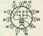
Fig. 703. Internal deflection plates are used in the electrostatically deflected
picture tube.
Dc voltages roughly equal to the second-anode voltage are fed to the deflection plates to prevent setting up undesired electric fields between the deflection plates and the second anode. Adjustment of these voltages permits centering of the raster. Two potentiometers are used for adjusting horizontal and vertical centering, respectively. When there is no voltage difference between the two sets of plates and the electron gun is perfectly aligned, the beam will travel midway between the plates. When one plate is made more or less positive than the other, the beam's starting position will move closer toward the more positive -plate, causing a corresponding shift in the centering of the raster.
Focusing is achieved with the aid of an electrode called the focus anode. This is often referred to as anode No. 1 in tube manuals and tube data sheets. The focus anode is typically operated at a voltage approximately 25% to 33-1/3% as high as the second anode voltage. Insertion of a potentiometer in the focus anode circuit permits the voltage to be adjusted for optimum focusing.
The second anode in electrostatic tubes comprises a cylinder as well as an internal Aquadag coating. The second anode's cylinder, in conjunction with the first anode, helps bring the electron beam to focus on the screen. The Aquadag, to which the second anode connects, collects the electrons emitted by the screen. Both the Aquadag and the second-anode cylinder also accelerate the electrons in the beam. Second-anode voltages in electrostatic tubes range from approximately 2,000 to 5,000 dc.
A third anode, known as the intensifier anode and referred to as anode No. 3, is used in some electrostatically deflected picture tubes. (The 14AP4 is an example of a picture tube incorporating an intensifier anode.) The intensifier anode consists of an Aquadag type coating near the screen. Its function is to increase screen brightness. The dc voltage applied to the intensifier anode is usually twice as high as the voltage fed to the second anode.
The deflection factor of an electrostatic tube could be of interest to the service technician on some occasions, particularly when he is substituting one (electrostatic) tube type for another.
The deflection factor indicates how much deflection voltage must be applied to the deflecting plates to produce an adequate sweep. It is usually expressed in terms of the average dc voltage needed to deflect the beam 1 inch in a given direction (horizontal or vertical). Two deflection factor ratings are supplied for an electrostatic tube-one rating is for the vertical deflecting plates, the other for the horizontal. These plates are referred to as D1, D2 and D3, D4, respectively. The deflection factor may be the same for both sets of plates or it may be different.
The set of plates closer to the electron gun is referred to as D3, D4; those further from the gun (and closer to the screen) are called D1, D2. The plates that are further from the screen are capable of providing greater deflection when a given value of deflection voltage is applied to them. These plates, D3 and D4, are said to have a higher deflection sensitivity than the D1, D2 plates. Deflection sensitivity is a measure of the distance the beam will deflect when 1 volt dc is applied between a pair of plates. This distance is usually expressed in millimeters.
Since the D3, D4 plates have the higher deflection sensitivity, less deflection voltage will have to be applied to them to move the beam a given distance across the screen. Inasmuch as the horizontal sweep needed is greater than the vertical (due to the 4-to-3 aspect ratio of the transmitted signal), it is logical to expect that the D3, D4 plates will be used to provide horizontal deflection and the D1, D2 plates for vertical deflection. This is usually the case. In some instances, however, when the horizontal deflection voltage is in excess of what is required, but the vertical deflection voltage is not quite adequate and cannot readily be increased by tube replacements, use of the more sensitive set of plates for vertical deflection may offer a quick means of adding the extra height. The picture tube will have to be rotated 90° if this change is made, to keep the picture upright.
The deflection factor is linked to a given value of second anode voltage. At higher anode voltages, the beam becomes "stiffer" or harder to deflect.
The service technician may, if the sweep is insufficient, want to know whether the trouble lies in the sweep system or the picture tube (the deflection sensitivity of a tube may, in some cases, be reduced because of a defect in the tube-excessive gas content, for instance, or a manufacturing flaw). To eliminate the sweep system as a source of the trouble, it must be determined whether the deflection voltage present is adequate to sweep the tube. To do this, multiply the deflection factor of the appropriate set of plates by the number of inches of screen surface the beam is required to cover.
Suppose the beam should be deflecting 6 inches vertically and the deflection factor of the vertical set of plates is 100. Then 100 volts is needed for each inch of deflection or a total of 600 volts peak-to-peak is required between plates. If this deflection voltage is found (by scope measurement) to be present and the .second anode voltage (as well as that of the third anode, if one exists) is normal, trouble in the picture tube is indicated.
Another characteristic that may concern the service technician on occasion is the cutoff voltage of the picture tube. This is de fined as the bias needed to extinguish the undeflected but focused spot produced on the screen (in the absence of deflection). This voltage varies considerably, depending on the tube type. In a 7JP4, it ranges from 72 to 168 volts; in a 14AP4, from 40 to 120. There are cases when full counterclockwise rotation of the brightness setting is unable to provide extinction of the electron beam. In such instances, when the technician wishes to learn whether the grid bias voltage present is capable of providing cutoff, he may measure the range through which the bias voltage goes and see if it coincides at any point with the cutoff-voltage range listed in a tube manual for the particular tube involved.
The cutoff voltage listing, incidentally, applies only when the typical second-anode voltage at which the tube is supposed to be operated is actually present.
Electromagnetically deflected picture tube Most TV receivers use electromagnetically deflected cathode ray tubes. Two pairs of coils, mounted around the neck of the tube in an external assembly referred to as the yoke, provide deflection. Focusing may be either electromagnetic or electro static.
The yoke
The yoke basically is made up of two pairs of coils, a magnetic core and an insulated casing. One set of coils comprises the horizontal deflection coils or the horizontal yoke; the other the vertical deflection coils or the vertical yoke. Each pair of coils is positioned (around the neck of the tube) at right angles to the other pair. The vertically positioned ones provide vertical deflection. The core increases the inductance of the yoke. It is generally grounded to minimize radiation from the yoke.
The deflection-angle rating of an electromagnetic tube is a measure of the angle through which the beam must be deflected to scan the picture tube properly in either the horizontal or vertical direction. When a tube is said to have a horizontal deflection angle of 66°, it means that the beam must be deflected 33° to either side of the center axis of the tube, or a total of 66°, to scan the picture tube fully in the horizontal direction.
If the deflection provided by the horizontal yoke is appreciably less than 66°, the sweep width will be inadequate; if it is greater than 66°, the sweep width may be excessive, causing picture in formation at the boundaries of the screen to be lost.
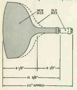
Fig. 704. Picture tubes can be made shorter as the deflection angle is increased.
A picture tube with a deflection angle of 110° is less than 16 inches in length.
This drawing shows the difference in length between two tubes having different
deflection angles.
In the case of round-faced tubes, one deflection-angle rating is generally specified by the tube manufacturer. This rating applies to both horizontal and vertical deflection. In the case of rectangular tubes, where a 4-to-3 aspect ratio is a built-in feature and cannot be changed, smaller deflection angles are needed for vertical than for horizontal deflections. Such differences may be taken advantage of by the tube manufacturer. In these cases, separate deflection angles may be listed; the larger one describes the horizontal deflection characteristic whereas the smaller refers to the vertical deflection. If only one deflection angle rating is given for a rectangular-faced tube, it usually refers to the diagonal angle.
---
Yokes are also given a deflection-angle rating. This rating is a measure of the deflection angle through which the yoke can swing the beam. The yoke deflection-angle rating should jibe very closely with that of the tube on which it will be used. For tubes with deflection angles of 50° to 60°, differences up to but no greater than 5° between yoke and picture-tube deflection angle ratings may be tolerable. In the case of deflection angles above 60°, differences of as much as 5° may not always be permissible.
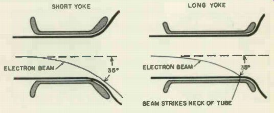
Fig. 705. Wide-angle yokes are shorter, use ferrite cores and have a higher
inductance than other types of yokes.
Early-make yokes were manufactured with a deflection-angle rating of about 52°. These angles have progressively increased in size to a maximum (at the time of writing) of 110°. Yokes capable of providing wider angles of deflection were required to match the higher deflection angles of large-screen tubes as these were developed. (Higher picture-tube deflection angles mean shorter tubes, as indicated in Fig. 704.) 3
[The 110° picture tube has an overall length of only 14 1 / 2 inches as compared with an average length of 20 inches for a comparable 90° tube. (Some 90° tubes are be tween 15 and 16 inches in length.) The 110° represents the diagonal deflection of a tube having a diagonal of 21% inches and a viewing area of 262 inches. It weighs less than 23 pounds. ]
To sweep a large-sized screen with a wide-angle yoke, the yoke must be very efficient. Let's see why this is so. The basic difference between the wide-angle yoke and its predecessors lies in the yoke length. The wide-angle yokes are shorter. With a long yoke, the possibility of increasing the deflection is limited by the fact that the electron beam tends to strike the neck of the tube if the angle is made too large (see Fig. 705). The shortening of the yoke necessarily decreased its sensitivity, or its deflection effect, since its inductance was reduced.
To compensate for this, ferrite cores were introduced. (Early yokes used magnetic cores made up of a large number of turns of iron wire.) The greater magnetic flux produced by the ferrite core compensated for the loss in sensitivity that the reduction of yoke length tended to produce.
To provide the increased high voltages needed in larger-sized tubes, the inductance of the horizontal yoke has been made successively larger over the years. The amount of high voltage developed in modern television sets depends on the amplitude of the pulses across the primary of the horizontal output trans former. This voltage, is, in turn, affected by the impedance of the horizontal yoke. Use of a higher-impedance horizontal yoke reduces the yoke's loading effect on the transformer primary, permitting higher voltages to be built up across this winding, thus
increasing the voltage applied to the high-voltage rectifier. The inductance of the horizontal yoke cannot be increased beyond the point where the size of the yoke becomes excessive, or the point at which the voltage differences built up between windings become too great for the insulation to withstand.
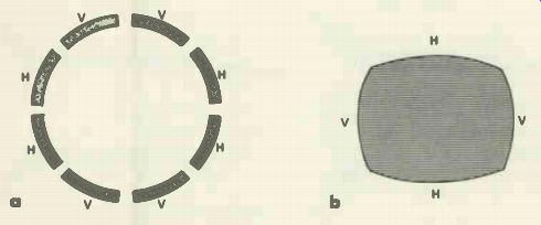
Figs. 706-a,-b. Cross-section of the yoke used in older receivers. The field
of this yoke is equivalent to four magnets placed as shown in the drawing
at the right.
Yoke characteristics and focus problems
Early-make yokes were responsible for nonuniform focusing. So long as the tube present had a relatively small screen, this nonuniformity was not obvious and created no problems. With the coming of larger-screen tubes, however, the impairment of focusing became much more noticeable. Let's consider why and how focusing was affected, then go on to see what yoke improvements were made to remedy the condition.
Focus is related to the size of the scanning spot. When proper focus has been attained, the size of the spot is minimum. If spot size increases during the course of deflection, defocusing results in the area affected.
When the magnetic field produced by the yoke is not uniform, the size and shape of the scanning spot change. If the magnetic field increases in the direction of deflection, the lines of force will increase as the scanning spot moves across the screen. The right-hand section of the spot may, in consequence, be in a stronger field than the left-hand side. The right-hand section will be deflected more than the left-hand one under these conditions, causing the spot to become elongated toward the right.
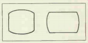
Fig. 707. Two examples of barreling. The sides of the raster are pushed out.
When the construction of the yoke is such as to cause the lines Fig. 708. Two examples of pincushioning. The sides of the raster are pushed in. Ui:1 El of force to decrease in the direction of deflection, the trailing edge of the spot will be in a stronger field than the leading edge, causing it to be deflected more. This will produce an elongation of the spot. The curvature in the flux lines of the field will, in both cases, increase the tendency toward elongation. The increase in spot size, as well as the change in shape, causes defocusing.
Early-make yokes tended to produce a nonuniform field be cause of their interlocked-winding construction. A cross-section drawing indicating this construction is shown in Fig. 706-a. The effect of such a construction is comparable to that produced by four permanent magnets, arranged as shown in Fig. 706-b. Be cause the field of the magnets is strongest in their immediate vicinity, deflection in these areas is greatest. The effect on the raster is barreling-a condition which causes a bowing outward of the raster sides (Fig. 707).
To eliminate this condition, the cosine yoke was developed.
This yoke is wound and assembled in such a way as to produce a much more uniform deflection field. The major drawback associated with the cosine yoke is that it tends to cause an effect called pincushioning (Fig. 708). Overlapping of the horizontal and vertical yoke windings in the regions where the corners of the raster appear causes more intense magnetic fields to be produced here than elsewhere. The resultant greater deflection at the corners produces a pincushion effect.
Anti-pincushion magnets
Anti-pincushion magnets are used to correct the tendency of the cosine yoke to produce a nonlinear raster with squeezed in sides. The magnets are variously known as anti-pincushion, pincushion, pincushion correction, picture straightener and beam corrector magnets. Small and nonstandard in size, frequently taking the form of a bar, they are mounted on or near the yoke at the side closer to the picture-tube screen (Fig. 709). The magnets come in pairs. One or two pairs of magnets may be used. A set may be found mounted above and below the yoke, as illustrated in Fig. 709, or at each side of the yoke, or both above and below the yoke and on each side.
Pincushion magnets are used on larger-sized picture tubes, particularly 24- and 27-inch round-faced units, not only to correct for pincushioning (which may be slight) but also to improve horizontal linearity. They are especially helpful in receivers that employ no horizontal linearity control.
Pincushion magnets are generally preset at the factory and locked tightly into place. They may require resetting, however, because of circuit changes, component replacements, operation of the receiver at low line voltage or other reasons.
Before an attempt is made to readjust the magnets be fairly certain that such readjustment is necessary. The following symptoms point to possible misadjustment of these units:
1. Presence of horizontal nonlinearity accompanied by pin cushioning at the sides of the picture and raster. The top and bottom and/or sides of the picture and raster may be affected.
The settings of the height and width controls will have to be reduced to make the pincushion effect visible. In some cases, the picture may be noticeably compressed at one side and expanded on the other. When top and bottom pincushioning is being checked for, examine the raster lines in these areas. If the raster lines are bent, misadjustment of the pincushion magnets that affect these areas is indicated.
2. Shaded picture corners.
3. A slight curve in the horizontal sides of the raster. The symptom could be mistaken for hum in the horizontal circuits.
It is worth noting that the picture may be more severely affected by the misadjustment of pincushion magnets than it would be if they were absent altogether.
Pincushion magnets may be reset with or without test equipment. A better and faster adjustment can be made if a bar or cross-hatch generator is used. The adjustment may also be made ...
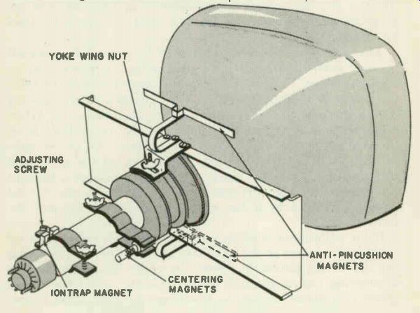
Fig. 709. This drawing shows how the anti-pincushion magnets are mounted.
... on a picture or test pattern, particularly one that has horizontal lines near the top and bottom and/or vertical lines at the sides.
The adjustment is correct when these lines-and/or the picture sides-are straight. The advantage of using a bar or cross-hatch generator lies in the fact that the size of the picture need not be reduced to observe its edges, eliminating the necessity for subsequent size and linearity readjustments.
When a bar generator is used, it is fed to the receiver either at the input of the video amplifier or at the antenna input terminals, depending on the type of generator employed. The spacing between bars serves as a measure of linearity. Non-uniform spacing indicates nonlinearity. Vertical or horizontal bars may be fed to the screen, depending on whether horizontal or vertical pincushioning is to be checked for. Vertical bars are used in testing for horizontal pincushioning; horizontal bars for vertical pincushioning. When a cross-hatch generator is available, tests and adjustments may be made without the necessity of feeding two different inputs successively to the receiver (since the cross-hatch generator output is composed of both horizontal and vertical lines). A cross-hatch pattern which shows non linearity and pincushioning is illustrated in Fig. 710. The appropriate magnets should be adjusted until the cross-hatch lines are straight.
The pincushion magnets are adjusted by moving them toward or away from the bell of the picture tube. They may also be rotated slightly. The closer a magnet is moved toward the tube, the greater is its effect on deflection. When the magnet is moving toward the tube the raster lines will be pulled toward it. When the magnet is moved away its effect on the raster lines is reduced. Each magnet can be moved away from the picture tube to start with; it is then brought slowly toward the tube until the curvature it affects is eliminated. When a magnet is brought too close to the tube, a corner of the picture and raster (or the pattern produced by a bar or cross-hatch generator) may be come shaded.
If the adjustment is being made on a picture (and centering controls are present in the receiver) there is no need for reducing the size of the picture to observe its edges. Simply manipulate a centering control to make an edge visible; adjust the appropriate pincushion magnet to straighten the edge, then expose another edge by a suitable centering manipulation, etc.
When the pincushion magnets are mounted by a brass or similar nonmagnetic strap that is readily bent, no tools are needed for adjustment. Simply bend the strap, bringing the magnet toward or away from the tube until the picture, raster or bar pattern is straight-sided and linear. (A slight rotation of the magnet may also be necessary during the adjustment process.) In some sets a rigid mounting is employed. A screw generally has to be loosened in these cases before the magnet can be adjusted.
If pincushion magnets are to be adjusted in a receiver that has a horizontal linearity control, the control should be correctly set before the magnets are adjusted. For best results, it is desirable either to remove the magnets or place them at a maximum distance from the picture tube before resetting the linearity control. When linearity and width have been made as satisfactory as possible without the magnets, adjustment of the latter is in order. The magnets should be set to minimize non linearity as well as pincushioning.
If the pincushion magnets have been mounted backward, it will not be possible to adjust them properly. Such improper polarization is likely to produce a compression along the center of the test pattern or picture. If such a compression is seen and ...
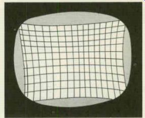
Fig. 710. Cross-hatch pattern showing nonlinearity and pincushioning.
... cannot be eliminated by suitable adjustments, try reversing the position of the magnets. When the magnets are color-coded and the code is known, a trial-and-error procedure is not necessary.
The set manufacturer's service data will generally call attention to such a code, if one is present.
Components associated with the yoke
A capacitor and two resistors (see Fig. 711) are in most cases connected into the yoke circuits and enclosed in the yoke casing.
Yokes are not infrequently condemned and replaced because of defects in one of these components.
During horizontal retrace, the magnetic fields in the horizontal yoke circuits collapse with great rapidity. A counter emf of substantial amplitude tends to be produced in consequence.
While the damper tube eliminates most of this ringing or oscillatory effect, some residual ripple may remain in the horizontal yoke coils. If nothing is done to remove it, the ripple may be coupled into the vertical deflection coils, causing wrinkles to form in part of each scanning line. The overall effect is one of dark and light bars at the left-hand side of the picture.
To eliminate this residual ripple, a capacitor of a suitable value is generally connected across one of the horizontal deflection coils. It is not attached across both because an imbalance exists with respect to the capacitance of each winding to ground. One a winding has a larger capacitance to ground than the other (since it is at a greater distance from ground than the other.) To restore the balance and insure linear scanning, as well as to filter out residual ringing signals, the capacitor is connected across ...

Figs. 711-a,-b. Resistors, usually 560 ohms, are shunted across the vertical
deflection coils. A single capacitor, with values ranging from 56 to 150 uuF,
is placed across one of the horizontal deflection coils.
… the winding with the smaller capacitance to ground. This is generally the upper winding or the one that is a greater distance from ground. Sometimes (particularly when a late-model cosine yoke is installed in sets using an early-make horizontal output transformer) connection of the capacitor across the lower winding will provide more satisfactory results.
Yokes and yoke components
When too large a value of horizontal yoke damping capacitance is used, severe ripple or waviness will be noticeable in a test pattern. Circles in the test pattern will be distorted, wedge lines in the horizontal wedges will become wavy and other symptoms may result as well.
A short in the horizontal yoke-balancing capacitor will greatly reduce the width of the raster; a characteristic keystoning will also be produced (Fig. 712). Damping resistors are connected across the vertical yoke to keep the circuit from oscillating or ringing during the vertical retrace. When they are too small in value, their shunting effect on the vertical coils will be too large and insufficient height is likely to result. When the resistors increase radically in value or open-circuit, a slight ripple in the horizontal wedges of the test pattern may be produced. Some distortion of the large outer circles of the test pattern may also result. Both symptoms are produced by the undamped or insufficiently damped vertical circuit ringing that is present in this case.
A severe reduction in the value of either resistor will greatly reduce picture and raster height and introduce keystoning.
Yoke adjustment
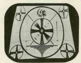
Fig. 712. The photo shows the effect of keystoning on a test pattern.
The yoke is invariably positioned as far forward as possible along the neck of the tube so that it presses against the flared portion of the tube. When the yoke is not sufficiently forward, dark areas are likely to be seen on the screen and a rectangular raster will not be present. Rotation of the yoke (clockwise or counter-clockwise) permits the picture and raster to be brought into horizontal alignment with the mask opening. Screws or nuts are provided to keep the yoke fixed in position. These nuts should be loosened before the yoke is adjusted and tightened when its setting is correct.
Vertical-yoke replacement
While the inductance of horizontal yokes has risen over the years, the inductance of vertical yokes has dropped. When a late model vertical yoke is used to replace an earlier type, mismatching to the vertical output transformer may be introduced. A smaller impedance will be reflected into the transformer primary in such cases, causing the vertical output tube to overload. The remedy is to substitute a vertical output transformer that matches the new vertical yoke.
Loosening "frozen" yokes Sometimes a yoke becomes stuck to the neck of the picture tube and cannot be moved without the risk of breaking the tube.
To loosen the yoke in such a case, apply approximately 50 volts ac to the horizontal coils. The polyethylene sleeve of the yoke will heat and soften under this treatment, freeing the yoke. The 50 volts ac may be obtained from a Variac type transformer. Or an old yoke whose horizontal windings are not defective may be connected in series with the yoke to be freed-that is, the horizontal windings of both yokes are connected in series. Line voltage is then applied to the combination. An ac voltage check may be made across the yoke that is being given the heat treatment, to make sure that the voltage being developed across it is about 50 or 60. Voltage should be applied to the yoke only long enough to loosen it; leaving the voltage on too long endangers the insulation between yoke windings.
Width control sleeve
In some TV sets, a metal sleeve that modifies the magnetic strength of the yoke is placed on the neck of the picture tube.
The width of the picture is regulated by adjustment of this sleeve.
Focus systems The problem of focusing has been attacked in two ways-by the construction of the picture-tube electron gun and by using external magnetic devices placed over the neck of the tube. Early television receivers containing 10- to 16-inch picture tubes such as the popular 10BP4, 12LP4, 14BP4, 14CP4, 16AP4, 16GP4 and 16KP4 used magnetic focusing in which the electron-beam concentration was controlled by the magnetic field of a focus coil or permanent magnetic focus device.
In recent years the low-voltage electrostatic-focus tube has been developed and is growing increasingly popular. This type-the 17HP4, 20HP4-A, 21ALP4-A, 24DP4-A, etc.-requires no external magnet. Its beam is focused by an electrostatic field set up by a potential applied to a focusing electrode (pin 6). Another relatively new development is the automatic-focus type tube, such as the 17KP4, 20JP4, 20VP4 and 21KP4, that needs no magnetic focus field or focus voltage.
Electromagnetic focusing adjustments
Electromagnetically focused tubes use a shielded coil for focusing. The field around the coil penetrates the glass neck and brings the electron beam to focus when the positioning of the coil and the amplitude of the direct current flowing through it are both correct. A potentiometer called the focus control permits the current through the coil to be regulated. Larger-sized tubes use stronger electromagnets than smaller ones do.
The focus coil should be positioned approximately 1 / 2 inch behind the yoke. If the focus coil is too close to the yoke, the yoke's deflection sensitivity will be reduced, decreasing the size of the raster. Corner shadows or poor focusing at the corners of the raster may be noticeable in such cases; the raster or semi-raster produced is also likely to rotate when the focus control is varied.
If the focus coil is positioned too close to the electron gun (away from the yoke), interaction of the focus and ion-trap magnet fields will take place, impairing focusing and causing the shape of the raster to be distorted.
To permit proper positioning of the focus coil, the yoke should be placed as far forward along the neck of the tube as possible.
The spacing between the two should be a minimum of 3/8 inch.
When proper focus cannot be obtained by manipulation of the focus control, it is very possible that the focus coil is too far from the yoke. The separation of the two should be checked in this case and suitable readjustments tried.
When it is impossible to remove corner shadows by these adjustments, the coil may be removed from the neck of the tube, reversed in position, then put back on the tube neck. (The ion trap magnet will also have to be removed, then put back and readjusted.) This procedure may prove helpful where other remedies are ineffective.
Another helpful servicing procedure is to reverse the direction of the current flowing through the focus coil. This can be done by unsoldering the leads to the focus coil at the terminals to which they connect, and transposing them. If neck shadow is reduced, centering is easier, and the angle the frame of the focus coil makes with the picture-tube is closer to a right angle than it previously was, the new connections are correct.
Cases occur where the focus control does not have the proper range to produce correct focus. Circuit changes are often made in such instances to suitably reduce or increase the current through the focus coil. On some receivers, however, a different technique is recommended by the manufacturer. This is the addition to--or the removal from--the focus coil of units called magnetic shunts. Adding a shunt unit increases the magnetic flux of the focus coil; removing one decreases it. Shunts are added or removed with the focus control at the center of its range, until the picture is sharply focused as well as centered. This technique makes it unnecessary to make circuit modifications where the range of the focus potentiometer is too narrow. Evidence that such a condition exists lies in the inability of the focus potentiometer to go through focus--i.e., provide an approximately center setting at which focus is better than it is at either side.
PM and EM-PM focusing
Focusing is achieved in many cathode-ray tubes by a permanent magnet mounted around the neck of the tube. Units that are a combination of electromagnet and permanent magnet are also used. The PM section reduces the drain on the receiver power supply and minimizes the number of turns needed in the coil; a potentiometer is used with the EM section, permitting a finer degree of adjustment than is possible with a purely PM focus magnet.
Both PM and EM-PM magnet assemblies may be readily and permanently damaged by careless or improper handling. Jarring or striking a focus magnet assembly can reduce its magnetism, impairing its ability to function properly. Improper storage of such units can damage them too. Leaving a focus assembly on a metal shelf or near metal tools may harm the permanent magnet by weakening its flux. Vibration and shock are likewise damaging and should be avoided during transportation, storage and servicing.
Adjusting PM and EM-PM focus assemblies
PM and EM-PM focus assemblies are moved along the neck of the tube and from side to side into a setting where focus is optimum, as in the case of an electromagnetic focus coil. In general, the correct setting is approximately 3 / 8 to 1 / 2 inch behind the yoke. A screw type adjustment is often present, permitting the PM field to be increased or reduced. In many cases a shaft that has a knurled metal knob that can be manipulated with the fingers is provided for fine focus adjustments. When a screwdriver adjustment is called for, a brass or nonmetallic screwdriver should be used to avoid damaging the PM unit.
One of the following troubles may be the cause of the adjustment difficulties in EM-PM focus assemblies:
(1) Incorrect positioning of the unit on the neck of the tube; (2) PM field too great; (3) PM field too weak; (4) EM winding connected in reverse.
Any of these conditions will make it impossible to attain proper focus by manipulation of the focus control.
An EM-PM assembly is generally placed so that the coil's front surface is about V t inch behind the rear of the yoke. If moving the assembly back improves focusing, the PM field is probably too strong. The assembly should, in such a case, be moved back until focusing can be obtained by focus control manipulation.
When resetting of the assembly does not provide proper focus, either the PM field is too weak or the EM winding is connected in reverse. When the field is too weak, the assembly must be re placed. To decide whether or not this field is weak, the possibility of a reversed winding must first be eliminated. The required test for this is performed as follows:
1. Obtain the best possible focus with the focus assembly moved up against the yoke.
2. Measure the voltage across the EM winding at this focus setting.
3. Move the assembly as far back along the neck of the tube as possible. Readjust the focus control to produce as good or almost as good a picture focus as obtained in step 1.
4. Measure the voltage across the EM winding at this focus setting.
If the EM coil is properly connected, the voltage across it will measure higher in step 4 than in step 2. If the voltage attained is lower or if step 3 does not provide an adjustment comparable to that obtained in step 1, a reversed EM winding is indicated.
If the winding is not reversed, as indicated by this test, and proper focusing cannot be obtained, a new focus assembly should be tried.
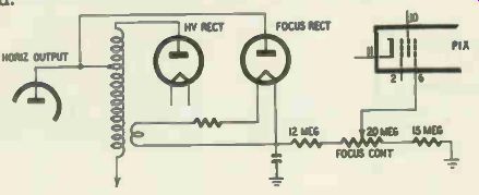
Fig. 713. High-voltage electrostatic focus.
When the PM field is excessive, reversal of the EM winding will decrease it and improve focusing temporarily. Eventually, how ever, the PM field will be reduced to zero because of the incorrect EM coil hookup, making the assembly useless.
Electrostatic focusing
An electrostatic focus system makes an external focus assembly unnecessary. When an electrostatic-focus system is used, the focus field is obtained by suitable construction of the electron gun. A focusing anode is used in the gun to help supply the required electrostatic field.
High- voltage electrostatic focus In this system (Fig. 713) the focusing anode is connected to a high dc voltage (between 1,000 and 5,000 volts). Because of its high potential, the focus anode draws some current, causing its voltage to vary when the current through it changes for some reason. Power-line voltage fluctuations tend to cause the current flowing through the focus anode to vary; the resultant change in the focus anode voltage introduces defocusing, making rather frequent focus control adjustments necessary.
A separate high-voltage supply is used in the high-voltage electro static-focus system. When the high-voltage rectifier tube in this supply loses emission or becomes defective, focusing will be im paired. A potentiometer in the high-voltage supply permits the focus anode voltage to be suitably adjusted.
The high-voltage electrostatic system is not widely used in TV sets. Soon after it was developed, superior low- and zero-voltage focus systems appeared.
Low- voltage electrostatic focus In this focus system (Fig. 714) the voltage required for the focus anode is between -100 y and +400 y approximately. The one advantage of such a system over high-voltage electrostatic focusing lies in the fact that it requires no separate high-voltage rectifier and associated components. A potentiometer in the B supply permits adjustment of the focus voltage.
Proper focusing depends on the ratio of the first and second anode voltages. A change in this ratio will introduce defocusing, necessitating a resetting of the focus potentiometer. Such changes are likely when the brightness control setting is altered or when the power-line voltage rises or falls. Variations in the voltage of the focus anode are more likely because this anode draws appreciable current.
Adjustment of the focus control does not cause the picture to go very noticeably in and out of focus, as with other focus systems.
Changes in focus are barely perceptible to the eye when a picture is on the screen and the potentiometer is rotated from one extreme to the other. A better focus adjustment can be obtained by setting the channel selector to an unoccupied channel and adjusting the control to a setting where the raster scanning lines look sharpest.
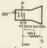
Fig. 714. The low-voltage electrostatic focus system depends for its action
on the ratio of the voltages between the first and second anodes.
When the cathode-ray tube is replaced in a low-voltage electro static-focus system and focus is not satisfactory, try connecting the focus anode to different B-voltage points in the receiver, leaving it attached to the point that permits best focusing.
Automatic or self-focus The superiority of the automatic or self-focus picture tube over its electrostatic-focus predecessors lies in the fact that it is much less affected by changes in the voltages of picture-tube electrodes.
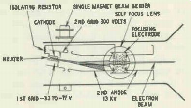
Fig. 715. Gun structure in the automatic or self-focus picture tube.
Variations in line voltage, brightness control re-settings, etc. are not likely to cause defocusing because of the structure of the electron gun (Fig. 715). In this type of gun (as in the older electro static-focus gun) the second anode is split into two sections and the focus anode is mounted within the gap. A large-diameter focus electrode is used whose field overlaps that of the adjacent electrodes. Since the voltage between the first and second anodes at one side of the gap is always identical with the voltage between the same two anodes at the other side, the focus field remains substantially constant. A resistor, internally connected between the cathode and the focus anode, keeps the two electrodes at the same potential, preventing the defocusing that voltage variations be tween them might introduce. No external connection to the focus electrode is required for most automatic-focus tubes.
An electromagnetic-deflection magnetic-focus tube may be re placed by a similar electromagnetic-deflection electrostatic self focus unit. Simply remove the EM or PM focus unit and install the new tube. If an EM focus coil was used with the original tube, substitute a resistor of approximately 5 watts whose value is the same as the resistance of the coil.
Adjusting focus on self-focus tubes
No locus control is generally available for the self-focus cathode-ray tube. Other means must therefore be employed to improve focus. Focusing in tubes of this type is greatly affected by the setting of the ion-trap magnet. It is true that there is only one correct setting for this magnet-the one that provides maximum brightness with no shadowing of the raster or distortion of its shape. When this setting is not perfect, however, brightness may not be noticeably impaired but focusing will.
To obtain optimum focus, set the brightness control at its normal position and turn the receiver off-channel. Carefully observe the raster scanning lines while you adjust the ion-trap magnet. At one setting of the ion magnet, the lines will appear sharpest. Make sure brightness is not reduced at this setting Leave the magnet at this optimum position.
If resetting of the ion-trap magnet does not provide sharp focus, reverse the magnet's position on the tube neck (i.e., slide it off the neck of the tube, turn it around, then slip it back on)
Readjustment now will often provide the desired results.
Focus adjustments on internal magnetic-focus tubes
When the tube uses an internal magnetic-focus system, an external focus unit will usually be found on the tube's neck. This is a metal sleeve and spring which acts as a shunt on the internal magnetic field and permits the latter to be varied. To adjust focusing, slide the sleeve back and forth until optimum overall focus is obtained.
Centering devices and their adjustment
In many older-make sets, and in some TV receivers of more recent vintage, centering of the picture is attained by potentiometer adjustments. In the case of electrostatically deflected tubes, the potentiometers regulate centering by changing the dc voltages on the deflecting plates. When the voltage on one plate of a set is equal to that of the other, the beam will tend to travel midway between them. When one plate is made more positive, the beam's starting point--i.e., its position when undeflected--will shift toward this plate, causing the raster to move in the same direction. Two potentiometers, one for vertical, the other for horizontal centering, are generally found in these electrostatic; deflection sets.
In some electromagnetic receivers, centering is achieved by regulating the dc current through the yoke coils by potentiometers.
Centering accessories on tube neck in receivers that have no centering controls, centering is often obtained by suitable positioning of the focus coil or magnet (when such a unit is present). The wing nuts or screws holding the coil in position are loosened. By moving the coil slightly in the proper direction and tilting it slightly backward or forward, the picture is centered with respect to the mask. The wing nuts or screws are then tightened. In receivers with centering controls, ...
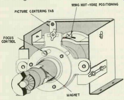
Fig. 716. Adjustment of the centering tab positions the picture.
... centering should be achieved, if possible, solely by readjusting the controls. Tilting the focus coil has an undesirable effect on the focus field and should be avoided or minimized.
In some receivers using a focus coil, and in most or all of those using a permanent-focus magnet, a lever on a plate or disk separate from but attached to the focus unit is employed for centering (Fig. 716). Sometimes, movement of the lever up or down provides horizontal centering; moving it right or left produces vertical centering. In other instances, up and down movement of the plate moves the picture up or down; sideways adjustment repositions the picture from side to side. Any nuts holding the lever in position must be loosened before it is free to be adjusted; these nuts are subsequently tightened.
In some receivers using PM or EM-PM focus units, centering is achieved both by a mechanical orientation of the focus unit and a suitable setting of a centering adjustment screw at the rear of the focus unit. The screw adjustment should be made after the focus unit has been reset to provide optimum centering.
In electrostatically focused tubes (and tubes using internal magnetic focusing), centering is commonly obtained by means of a dual ring magnet. Manufactured in the form of two disks, mounted on a nonmagnetic form or tubing, the assembly is placed around the neck of the tube approximately IA inch behind the deflection yoke. Rotation of two tabs or levers attached to the magnets (one per magnet) provides centering.
To adjust a centering unit of this type, move the levers toward or away from each other until the picture is centered. When the levers are closest to each other, their effect on centering is maximum. Rotation of the magnet as a whole may also be necessary to obtain proper centering. To minimize the defocusing that the centering magnet tends to introduce, it should be positioned as close to the yoke, and consequently as far from the electron gun as possible.
A defective or improperly designed ring magnet will impair focus. To test such a magnet, bring the test pattern or raster into normal focus, then rotate the two tabs from 0° to 360°. No change or only a slight change in focus should be noted during this procedure.
A clamp type centering device completely separate from the focus assembly is used on the neck of some electrostatically focused picture tubes (Fig. 717). To adjust such a unit, rotate it to the left or right and turn the knob at its top until centering is proper.
When thumbscrews are found on centering magnets, use thumb and fingers only to adjust them. If pliers or other tools are employed, the magnet is likely to be damaged.
Ion trap and magnet system
One of the most important components in the TV receiver is the ion-trap magnet. Its importance lies in the fact that a mis adjusted ion magnet can (1) irreparably damage an expensive picture tube and (2) reduce brightness and (in the case of an automatic-focus) impair focus.
Before we go any further, a common error in nomenclature should be noted. Service technicians-even manufacturers-often refer to the external magnet used in ion-trapping systems as the ion trap. This is incorrect. The ion trap is inside the picture tube. The external magnet is the ion-trap magnet or ion magnet for short.
Need for an ion-trap system
Ions are electrically unbalanced or charged atoms. An atom that has gained or lost one or more electrons becomes an ion.
In the first case, the charge of the ion is negative; in the second, it is positive.
Ions are always present in varying amounts inside cathode-ray tubes. The cathode emits ions as well as electrons. Additional ions are formed when the electron beam strikes gas atoms present ...
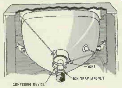
Fig. 717. The centering device is mounted on the neck of the picture tube.
... within the tube, knocking off or adding electrons to them.
Positively charged ions, or cations, are attracted toward the cathode and cause no trouble. Negatively charged ions, or anions, however, tend to be attracted toward the screen. If they were deflected over the entire surface of the screen, they wouldn't do much harm. Ions are, however, about 2,000 times as heavy as an electron and are not appreciably deflected by the magnetic fields that move the electron beam across the face of an electromagnetic picture tube. Ions thus tend to bombard the center of the screen.
A round discolored area at the center would result if some means were not used to prevent such concentrated bombardment.
An ion trapping system prevents this undesired condition. The structure of the electron gun is such that both electrons and ions are deflected toward the neck of the tube. The external ion magnet (when properly adjusted) redirects the electrons back to a path in line with the picture-tube screen. The ions, however, are too heavy to be attracted back and thus never reach the screen.
Types of ion trap
Several types of ion traps are used in cathode-ray tubes. Recognition of the type present has a bearing on the adjustment as well as the replacement of the associated magnet.
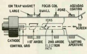
Fig. 718. The straight gun requires a double ion-trap magnet.
In the straight-gun (also called the slashed-field or diagonal-cut) ion trap the axis of the electron gun coincides with that of the tube neck (Fig. 718). A double ion-trap magnet is used around the tube neck. The warped electrostatic field set up in the oblique gap between the first and second anodes causes both ions and electrons to be deflected toward the neck of the tube. The rear or larger of the two ion magnets bends the electrons back to some extent. The smaller front magnet-the weaker of the two-finishes the bending job, causing the electron beam to travel through the second-anode aperture. Two internal pole pieces known as flags are attached to the gun. These units help shape the magnetic ...
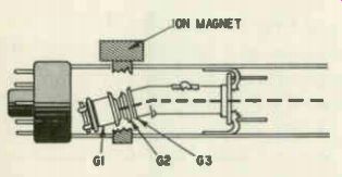
Fig. 719. The entire gun is bent in the tilted-gun system.
... field. They are important to the service technician as a guide in the adjustment of the associated ion magnet.
In the tilted-gun system; the entire gun is tilted about 3° with respect to the axis of the tube neck (Fig. 719). This causes the gun to look as if it had been inserted into the neck in a slightly crooked fashion. There are no pole pieces or flags in this system.
A single ion-trap magnet is employed on the neck of the tube.
The electrostatic field present between the first and second anodes originally directs both ions and electrons toward the tube neck.
The external ion magnet bends the electron beam back in the direction of the screen.
The bent-gun is similar to the tilted gun (Fig. 720). In the bent gun system, however, only a portion of the gun is bent whereas the entire unit is bent in the tilted gun system. The first anode has a bend of approximately 5°. The two preceding grids are in line with the first anode. No pole pieces or flags are present in this system. Because of the bend in the first anode, electrons and ions are originally directed toward its sides or walls. The single ion-trap magnet employed pulls the electrons back so that they take the correct path.
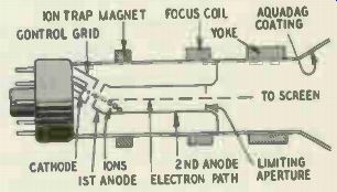
Fig. 720. Only a portion of the gun is tilted in the bent gun.
Ion-trap magnets are commonly PM units. In some of the older-make receivers, however, an electro-magnetic ion magnet is employed. A single ion magnet is used for some picture tubes; a double one in the case of others, depending on the tube's gun structure. Two ring magnets or two pairs of pole pieces will be found in the double-magnet unit.
Symptoms of improper ion-magnet adjustment
Inadequate picture brilliance is most commonly the chief symptom produced by an ion magnet that is slightly out of adjustment.
Picture contrast is likely to be unsatisfactory when the reduction in brightness is appreciable. In low-voltage electrostatic-focus tubes, slight misadjustment of the ion magnet may prevent proper focus. Peculiar operation of the brightness control (brightness decreases towards the extreme clockwise setting of the control) may point in some instances to an improperly adjusted ion-trap magnet. In severe cases of misadjustment, corner shadows and a semicircular raster will be noted.
Symptoms of a defective ion- trap magnet
Certain symptoms point to a defect in the ion magnet itself rather than its setting. When a slashed-field gun with internal flags is present and the ion magnet has to be moved more than 1/4 inch away from its proper setting with respect to the flags, or has to be pushed up against the focus coil to obtain the brightest raster, the magnet is probably weak. In any case, when an ion magnet has to be set in an abnormal position (too far forward or back), a defect in the unit is generally indicated (assuming that the correct type of magnet is being used). With an EM type ion magnet, an improper current, or the absence of current through the coil of the unit, may be responsible for its unsatisfactory operation.
When to check the ion-magnet setting
When the symptoms present point to a possible misadjustment of the ion-trap magnet, its setting should be checked. The setting should also be checked even when no recognizable symptoms of misadjustment are visible, under the following circumstances:
1. Whenever a tube or component is replaced in the sweep or high voltage stages, if the substitution has changed the high voltage appreciably.
2. When the set has been moved from one location to another, recheck the ion-magnet setting even if the picture brightness seems adequate.
3. When other accessories (such as the yoke, focus coil, etc,) have been adjusted.
4. When a TV receiver is first installed.
5. When optimum performance is being sought in a weak-signal area.
The setting of the ion-trap magnet depends to an extent on the brightness control setting. Let's assume the ion magnet has been adjusted in a strong signal area at a certain brightness set ting. If the set is moved to a weak-signal location, the brightness setting will most probably be different. Repositioning the ion magnet, with the brightness control rotated to the point at which it will be positioned during receiver operation, can produce an effective increase in the contrast of the picture. (There is a tendency to advance the brightness control beyond normal limits in weak-signal areas to make the picture more acceptable. Advancing the brightness setting causes the picture-tube bias to be come incorrect and degrades contrast. If greater brightness can be obtained by a resetting of the ion magnet, the brightness control can be left at a more nearly normal level. The picture contrast is effectively improved as a result.
Adjusting the ion- trap magnet If the ion magnet is being adjusted "from scratch"--i.e., with no picture or raster visible because the magnet is so far from its correct setting-set the brightness control to a low level. Then move the ion magnet back and forth and rotate it until the screen becomes illuminated. If the technician is uncertain whether the brightness setting is high enough to produce an illuminated screen, but is reluctant to leave it at a more advanced setting for fear of possible damage to the screen, the following procedure may be used: While adjusting the ion magnet, move the brightness control continuously from zero to a high setting, then back to zero. The control will not be at a high setting long enough to damage the tube if the ion magnet is misadjusted; it will, however, be there long enough to permit some illumination to be visible on the screen when the ion magnet approaches the proper setting.
When the screen is illuminated, the magnet may be quickly adjusted (by rotation as well as back and forth movement) to produce maximum brightness. The brightness control should next be turned to a point where the raster's brilliance is low and its scanning lines clear and well-focused, to simulate the conditions present when a picture is on the screen. The ion magnet is then readjusted to provide maximum brightness. The setting should be rechecked if other picture-tube accessories are subsequently adjusted.
The position of the ion magnet should not be changed to remove shadows or rounded corners from the raster if the brilliance of the raster is reduced in the process. Re-adjust the other accessories (yoke, focus magnet, etc.) to eliminate such symptoms.
In some cases, placing the ion-trap magnet in either of two positions along the neck of the tube will provide a good brightness level. The correct setting in such instances is the one closer to the tube base.
A faster positioning of the ion magnet will be achieved, when the adjustment is started from scratch, by placing the magnet into an initial position close to its correct setting. This may be done as follows: In the case of the straight-gun (slashed-field system) using a double magnet, the larger of the magnets should be nearer the tube base, directly over the flags. If the flags aren't clearly appar ent, set the unit so that the larger magnet is directly over the first anode or grid No. 2.
When a tilted gun is present, place the single magnet over the first anode.
When a bent gun is used, the single ion-trap magnet should be initially placed over the slant cut.
The setting of the ion magnet is affected by the amount of high voltage applied to the picture tube's second anode. The final adjustment of the magnet should therefore be made after any high voltage faults present have been repaired and the horizontal control reset.
Care should be used in adjusting the ion magnet to avoid breaking the neck of the picture tube.
A blue or green fluorescent glow in the neck of some picture tubes warns of a mis-adusted ion-trap magnet. The glow is produced by a luminescent coating at the aperture of one of the anodes. The glow is normally scarcely noticeable; it becomes very apparent, however, when the electron beam is off center. In tubes of this type, the ion magnet should be positioned to produce a minimum amount of fluorescence in the neck.
Damage due to misadjusted ion-trap magnet
A misadjusted ion magnet can be responsible for an ion burn on the screen of the tube. This is an area about the size of a half dollar or less, light brown or yellowish in color. The burning away of the phosphor material on the screen by a concentrated ion bombardment is responsible for the discoloration. Ion burns are most visible-and annoying-when light picture information is superimposed over them.
A far more likely consequence of ion-magnet misadjustment is damage to the top disk of the high-voltage anode cylinder. When the adjustment is correct, beam electrons stream through the aperture in this disk. When the adjustment is incorrect, on the other hand, the direction of the beam is improper and some of the electrons in the beam may now bombard the edges of the aperture. The heat generated by this bombardment can vaporize parts of the aperture, as illustrated in Fig. 721. The damage will impair focus (since the aperture regulates the size and shape of the beam), causing a blurred or poorly defined picture. In some cases, bits of metal that have been torn away from the aperture are deposited on the screen, producing dark areas there.
Gases are given off by the section of the anode being bombarded, due to the excessive heat generated. These gases contaminate the picture tube's cathode and thus tend to shorten tube life.
The higher the second-anode voltage, the greater is the risk of damage to the gun due to ion-trap magnet misadjustment because the beam electrons travel faster when the second-anode voltage is higher. When misdirected electrons hit the edges of the aperture at a higher speed, more heat will be generated and more damage done. If the heat produced at the accelerating anode exceeds 6 watts, approximately, the metal will vaporize. The technician must be all the more careful in avoiding damage when handling costly, larger-sized tubes, since these are fed higher second-anode voltages.
If the ion-trap magnet is out of adjustment and the brightness control setting is too high, some tubes may be irreparably damaged in 15 seconds. This makes it imperative for the technician to make sure that a set with a dark screen (that is undergoing tests) is not permitted to operate for any length of time with the brightness ...
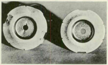
Fig. 721. Improper setting of the ion-trap magnet can cause damage to the
gun structure in the picture tube.
... control setting advanced, unless the technician is sure the ion-trap magnet is not out of adjustment. It also becomes mandatory to keep the brightness control setting low when the ion-trap mag net is being adjusted "from scratch."
Dark spots may develop at the center of the screen in some receivers for reasons other than ion-magnet misadjustment. Irregularly-shaped screen markings are generally the result of defects in the screen material. In some receivers, a dark spot approximately 4 inches in diameter may be seen on the picture-tube screen when the tube is too close to the safety glass. An electrostatic discharge may take place from the center of the screen to the glass, reducing the high voltage at the screen center and thus producing the dark spot. The spot will disappear when the chassis is removed from the cabinet. The remedy is to reposition the chassis (if the picture tube is mounted on it) as far back in the cabinet as it will go.
Replacing the ion-trap magnet
Ion-trap magnets deteriorate with age. In some cases, jarring may have damaged them. In others, they may have become partially demagnetized by placement near a strong magnetic field. Reduction in picture brightness results from such deterioration.
When the picture and raster are below normal in brightness, brilliance cannot be increased by ion-magnet readjustment and tube-element voltages are correct, substitution of a new ion mag net (as a test) is warranted. This substitution is particularly logical when the setting at which the original magnet produces maximum brightness is considerably removed from normal.
Certain factors must be taken into consideration when an ion trap magnet is replaced. In the first place, the correct type of magnet must be used: single or double. A straight gun calls for a double magnet whereas other guns require a single unit.
The strength of an ion magnet should be the same as the nominal rating of the unit it is replacing. The rating required depends on the type of gun used and the second-anode potential.
Tubes with electrostatic focusing generally employ ion-trap mag nets whose field strength is approximately 5 or 10 gausses less than comparable magnetically focused tubes. This is so because the external focus magnet on the magnetic-focus tubes shunts (and thus reduces) the field of the ion-trap magnet, making a higher strength necessary.
When the service technician is uncertain what the strength the substitute magnet should have, an adjustable test magnet will prove helpful. Magnets are available whose strength may be varied from approximately 32 to 55 gausses or higher. To check for required strength with such a magnet, proceed as follows: Set the magnet strength close to minimum and rotate and slide the unit along the picture-tube neck until the maximum bright ness setting is reached. Now increase the strength, going in steps toward the maximum. Each time the unit's strength is readjusted, its setting should likewise be altered to provide the greatest bright ness. When a strength setting is reached beyond which an increase produces no corresponding rise in brightness, the strength of the ion magnet is correct. A non-variable magnet which produces the same level of brightness at the same brightness control setting is now substituted for the variable test unit.
Service technicians who use ion magnets with strengths in ex cess of what is required, and note no adverse effects, may wonder why a fuss should be made over getting a unit of the proper rating.
The answer is that while a too-strong magnet may do no harm in the case of an electromagnetically focused tube, it is very likely to distort the focused scanning spot if the tube is electrostatically focused. Excessive field strength in the magnet is equivalent to a change in the focus voltage of the tube and causes the focus action of the first electron lens system (in which the focus anode plays a part) to be altered. With either an electrostatically or magnetically focused tube, an ion magnet that is too strong may result in an adjustment that is too close to the base of the tube. A bright ness peak may be unobtainable anywhere along the tube's neck when the strength of the ion-trap magnet is excessive.
When the magnet is too weak, insufficient brightness, neck shadows and improper centering may result.
In general, when the ion-trap magnet being substituted has to be placed too close to the base of the tube, one of lower strength should be tried. If the ion-magnet setting is too near the bell of the tube, a unit with a higher field strength should be substituted.
A small bar magnet may be used to verify whether the ion mag net substituted is too weak. To make this check, bring the north pole of the bar magnet slowly toward the ion-trap magnet. Then bring the south pole of the bar magnet toward the ion-trap mag net. If an increase in screen brightness occurs at any time during this process (and the setting of the ion trap magnet is correct), the ion trap magnet is too weak.
An arrow or colored dot is often present on the magnet. Make sure that this arrow or dot faces the bell of the picture tube (not the base). When a double ion magnet is being substituted, the larger of the two magnets should be closer to the base of the picture tube.
Testing and repairing picture tubes
Determining whether trouble exists in a picture tube is not always simple. The best test-substitution-is generally too time consuming to be used except as a last resort. Besides, a substitute may not always be available. Tube checkers have a limited value, particularly where intermittent troubles are concerned. Careful analysis of symptoms and elimination tests offer the best trouble shooting approach in most cases.
Picture-tube "repairs" also merit discussion. The picture tube is generally the most expensive component in the receiver and customers are not always anxious to pay the price of a replacement. A consideration of when repairs are feasible, how to make the repair called for and how reliably the tube (or its socket) can be expected to function after such servicing is therefore warranted.
To test tubes successfully for the various defects that may develop in them, the service technician must know: (1) what troubles are possible; (2)symptoms and other clues that point to the presence of one particular trouble; (3) test procedures suit able to its detection.
Possible troubles in picture tubes The following defects may develop in picture tubes: open filament; open circuits in other elements; poor solder connections at the base prongs; partial filament short; short or leakage between cathode and filament; short or leakage between cathode and grid; loss in cathode emission; development of excessive gas; defects in the gun; screen troubles; arcing at the second-anode connection.
Poor socket contacts may also prevent proper operation.
Loss of emission
Brightness is reduced when the emission of the picture-tube cathode drops. Since other component defects may also lower brightness, the problem arises of determining whether the fault lies in the tube or elsewhere. If the following symptoms are associated with the loss in brightness but sound is normal, the tube is almost certainly the source of trouble. (1) The picture takes several minutes to develop on the screen (when the set is turned on after being off for a while). (2) The ion-trap magnet (assuming it is normal) must be moved toward the base of the tube, away from its normal position with respect to the electron gun, to obtain maximum brightness. (3) The darkest tones in the picture aren't really black; the lightest areas don't have clear whites.
A picture tube whose emission has decreased considerably is generally incapable of reproducing blacks properly. When the contrast setting is advanced in an attempt to improve the rendition of black tones, picture highlights often assume a silvery appearance. The picture may even become negative when the contrast control is turned up far enough. In some instances, the raster brilliance decreases when the brightness control is advanced be yond a certain point.
If any uncertainty is felt as to whether the picture tube or an associated component is at fault, tests of the tube-element voltages and resetting and/or replacement of the ion-trap magnet should indicate whether substitution is a logical next step. The same tests will be helpful when the symptom is a dark screen and a complete loss of cathode emission in the picture tube is suspected.
Rejuvenation as a remedy for reduced emission
The merits of rejuvenating low-emission cathode-ray tubes have been hotly argued. It is not our intention to endorse one viewpoint or the other but simply to point out the pros and cons and to discuss techniques.
Rejuvenation, or cathode reactivation, works only in some cases. Proponents claim that as many as 80% of low-emission tubes can be restored with proper techniques. Those opposed estimate that a figure closer to 30% would be more accurate. Opponents also point out that the continued successful operation of a rejuvenated tube is very uncertain. Repeated service calls to rejuvenate the same tube are not likely to endear technician to the customer. If the tube fails in a short time, the prestige of the technician is bound to decrease.
Rejuvenation techniques
Commercial rejuvenators generally use one of two methods: flashing, or continued application of increased filament voltage.
In the flashing method, an increased heater voltage--approximate ly 1.5 to 2 times normal-is applied to the picture-tube filaments for 1 or 2 minutes. The overvoltage is then reduced to between 1.1 and 1.3 times normal and applied for 1 to 2 hours. This procedure, according to its advocates, changes the contaminated barium compounds in the cathode to the pure barium originally present.
In reactivation via a sustained filament-voltage boost, an over voltage of 25%--in some cases, even greater-is permanently applied to the picture-tube filament by a booster unit consisting of a transformer or autotransformer. Manufacturers of such units claim that picture-tube heaters are designed to stand up under a 100% overload for a considerable length of time to allow "curing" of the cathode surface during the manufacture. Because of this, the tubes can presumably stand up under the overvoltage produced by the booster. Opponents of this view state that the tube sub jected to such an overload will not last long enough to warrant the bother and expense of a booster.
Cathode defects
Not infrequently, a technician is uncertain whether emission trouble is responsible for the symptoms present.
Perhaps a checker has given the tube a clean bill of health but the technician is still suspicious of it. A substitute tube of the correct type may not be available in the shop at the moment or the technician may be working in a customer's home. Under such circumstances, the test described next (when used in conjunction with an analysis of symptoms) should be helpful in determining whether picture-tube cathode emission trouble is actually present.
Basically, the procedure consists of viewing the undeflected scanning spot on the screen. The scanning spot, we may remind the reader, is actually the image of the picture-tube cathode. Inspection of this image can tell us a great deal about the cathode's condition.
To perform the test, remove the yoke and focus coil (if one is present) from the neck of the tube, without disconnecting these units from their circuits. Removal of the deflection fields will permit the undeflected scanning spot to appear on the screen. If a somewhat larger image of the spot is desired, a PM focus magnet may be inserted on the neck of the tube and moved as close to the bell as possible. The ion-trap magnet (if one is used) should be left on the neck.
Care must be taken during the test to avoid damage to the screen. The possibility of damage is present because the electron beam remains concentrated on a small area of the screen. Turn the brightness control to minimum before the receiver is turned on. After set is on, turn up the brightness control a small amount and adjust the ion magnet for maximum brightness. When this adjustment has been made, leave the brightness setting advanced only far enough to produce a clear image of the scanning spot. If this caution is not observed, the picture-tube screen is likely to be damaged.
Figs. 722--a through j illustrate the kinds of spot that may be seen on the screen. Figs. 722-a,-b show what the spot will look like when a new good tube is present. Note the round, uniformly illuminated appearance of the spot in this case. Fig. 722-c shows what the scanning spot will look like when the tube has been in use for some time. The scattered light shadows are normal. In Figs. 722-d,-e,-f the shadows become progressively darker and more numerous. There is little or no cathode emission from the dark areas. Tubes that produce spots of this kind may or may not perform properly. If a picture-tube checker indicates that the emission is normal, the tube can be considered as still usable. Figs. 722-g,-h-i and j show scanning spots in which extensive areas are dark. The shape of the spot in these cases is effectively distorted as well. Tubes that produce such scanning spots will have impaired focus as well as inadequate contrast.
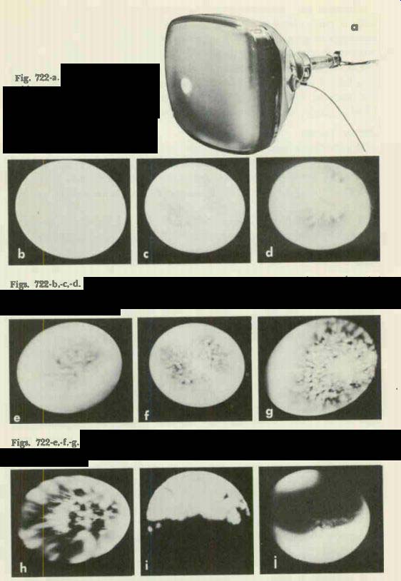
Fig. 722-a. The photo shows the appearance of the scanning spot on the picture-tube
screen.
Figs. 722-b,-c,-d. The photo at the left shows the appearance of the scanning spot in a new tube. The other two photos illustrate the effect on the scanning spot after the picture tube has been in operation for some time.
Figs. 722-e,-f.-g. These photos show how the scanning spot becomes progressively worse. Note the distortion of the spot and the appearance of shadows.
Figs. 722-h,-i, -j. These photos of the scanning spot indicate that a large area of the picture-tube cathode is dead. The dark shadows mean loss of cathode emission. The scanning spots are also severely distorted.
The test just described is a useful supplementary one to a test with a tube checker. When the tube checker indicates that the emission is passable, but a scanning-spot inspection reveals that large cathode areas are dead, the verdict of the spot-inspection test is the more reliable one. (It is assumed the symptoms pointing to a loss of emission in the tube are present.) If emission reads be low normal and the spot resembles one of those shown in Figs. 722-h,-i, and j, replacement of the tube is also called for.
Gassy tubes When electrodes in the picture tube become overheated, they give off gas. The getter absorbs released gas to a certain extent.
When the gas is excessive in quantity, however, or the getter has become inactive, excessive amounts of gas accumulate in the tube.
A tube that has an appreciable amount of gas in it is called gassy. The positive ions formed by collisions of electrons with gas atoms tend to lower the grid bias, impairing the operation of the tube.
Various symptoms may be introduced when a picture tube be comes gassy. When the sync take-off point is in the grid circuit of the picture tube, synchronization may be upset (due possibly to reduction in sync pulse amplitude as a result of grid current flow). If the receiver uses a keyed agc circuit, the out-of-sync condition will affect the agc voltage output, causing picture contrast and sound to be impaired. When excessive grid current flows be cause of the reduction in bias produced by the gas, a dark picture, even no picture at all (dark screen), is possible. In other cases, it will not be possible to reduce illumination to zero by manipulation of the brightness control. Retrace lines may be visible at normal brightness control settings. Poor focus, insufficient sweep or a negative picture may result from a gassy condition in the picture tube.
If a picture-tube grid-to-cathode voltage check produces appreciably different readings with the tube in and out of its socket, the picture tube may be gassy. (A leaky coupling capacitor or a grid-to-cathode short in the tube may also be the source of such discrepancies.) A good test for verifying whether gas is actually present may be made as follows:
1. Let the receiver warm up by operating it for several minutes.
2. Prepare to make a dc voltage check between the picture-tube grid and cathode.
3. Remove the picture-tube socket and very quickly connect the voltmeter test prods between grid and cathode. If the grid is positive with respect to the cathode, positive ions have accumulated at the grid and the tube is gassy. (If the grid reads negative with respect to the cathode, an electron accumulation on the grid is indicated. This is normal.) "Sparkers" are commercially available that detect the presence of gas in a picture tube. These units are also used to clear shorts between picture-tube electrodes.
Gas may, in some cases, reveal its presence by producing a pinkish glow in the area near the electron gun. A milky-looking getter is another indication of gas. It may readily be viewed when the glass opposite it is clear. (A little "window" is sometimes provided in the internal Aquadag near the getter to permit inspection.) There is no practical remedy for removing gas from a picture tube. Another tube must be substituted for the defective one.
Leakage of minute amounts of air into a cathode-ray tube will produce symptoms similar to those caused by gas. Usually silvery in appearance, the getter will look black or milky in color.
Filament troubles
An unlit picture-tube filament may, in most cases, be detected by visual inspection. When a visual check is not practical for some reason, feel the neck of the tube (after the set has been on for a minute or more) to see if it is heating up.
If the source of the trouble is an internal open in the filament, replacement is called for. Not infrequently, however, a poorly soldered filament connection is responsible for the apparent open circuit. Resoldering the base filament connections, whether or not they look as if they need it, is a wise preliminary check when an open heater seems to be present.
An ohmmeter check will often indicate when such resoldering is definitely called for. To make such a test, connect the ohm meter leads between the filament prongs of the picture tube, with the tube out of its socket. If the filament is cold, it should read about 2 ohms (assuming the heater current rating is .6 ampere and the heater voltage 6.3, as is common). Leaving the ohmmeter leads connected to the pins, tap the base of the tube lightly with a small screwdriver or similar light tool. If the meter reading varies appreciably, resoldering of the filament pins is called for. (Make sure the contact of the meter leads to the tube filament pins is not interrupted during the above test.) A retest when the resoldering job has been completed and the pins have cooled, will indicate whether trouble was really present here in the first place.
Defective socket contacts (as well as poor base prong connections) may be responsible for intermittent or continuous filament opens. Measuring the filament voltage from the top of the socket (with the picture tube out of the socket), while tapping the socket and wiggling the socket contacts, will often determine whether the trouble lies here. An appreciable variation in the voltage during the tapping and wiggling tests calls for a socket replacement. (It is assumed that the variation cannot be attributed to interruptions of the contact between the voltmeter leads and the socket contacts.) A partial short circuit in the picture-tube heater winding may occur in some cases, reducing the filament voltage of the tube and lowering the maximum screen illumination. When the picture-tube cathode is in good condition and the line voltage is normal, a partial filament short that reduces the filament voltage by 10% or 15% will not necessarily impair receiver performance. When the filament voltage is reduced more than 15% by the short, replacement of the tube is generally necessary.
A word on detecting the short. If the filament supply voltage of the cathode-ray tube is normal or slightly above normal with the tube out of its socket, but drops appreciably below normal when it is in its socket, a partial filament short in the tube is indicated. In the case of series-filament circuits fed from a selenium rectifier, the voltage on the filaments of tubes in series with the picture tube will be normal, while the c-r tube's heater voltage will be below normal if a partial filament short is present.
When the reduction in filament voltage is less than 15% but set performance is noticeably affected, use of a separate filament transformer for the picture-tube may be helpful. Removal of the loading effect of other tube heaters will boost the c-r tube's filament voltage, permitting continued use of the tube.
When the filament of a picture tube is internally open. no permanent repair can be achieved. A temporary weld can, however, be made in certain instances that permits operation of the tube for as long as several hours. Since the technician may conceivably run into cases where such an emergency repair is desired, the procedures used to effect the weld will be briefly described.
One technique consists of sparking a high ac voltage across the filament terminals. In another method, a capacitor with a capacitance of 100 to 200 uf is charged to several hundred volts dc, then discharged across the tube's filaments. The methods described will be temporarily successful only in (some) cases where the filament has broken because of physical shock. No success can be expected when excessive filament voltage, or a loss of the tube vacuum, has caused the filament to open in one or more places.
Heater-to-cathode shorts
Heater-to-cathode shorts are likely because of the close spacing between heater and cathode. The heater actually touches the cathode sleeve in one or more places, with only an insulating coating on the heater separating the two electrodes. When this insulation breaks off at a point where the heater is in contact with the cathode sleeve, a cathode-to-heater short will frequently result.
Cathode-to-heater shorts may be continually present, or they may occur only after the tube has been in operation for some time.
Possible symptoms (depending on the circuit present) include: washed-out picture, no picture, raster normal, black-and-white (hum) shading in the picture.
The presence of a cathode-to-heater short may be verified in most instances by an ohmmeter check made between these electrodes while the picture tube is still hot but disconnected from its socket. The ohmmeter section of a VTVM should preferably be used for such a test, with the meter set to the highest resistance scale to permit detection of small amounts of leakage.
Cathode-to-heater shorts are sometimes cleared by application of the line voltage between the two electrodes (tube disconnected from its socket). The method is not recommended, however, because use of such a high-current source may result in damage to the cathode. A better technique lies in using a high-voltage low-current source-the high-voltage power supply of a TV receiver, for instance.
To clear the short via this method, disconnect the picture tube from its socket and connect the cathode prong to the receiver chassis by means of a wire terminated in alligator clips.
Connect another wire to the plate cap of the horizontal output tube. Now touch the free end of this high-voltage lead to either of the filament prongs, letting the wire contact the prong only momentarily. Do this several times in succession. If the short does not clear immediately, repeat the process, gently tapping the neck of the tube with a pencil or other light tool (Fig. 723) during the time high voltage is applied. The tube need not be removed from the cabinet for this repair operation.
When a cathode-to-heater short cannot be eliminated, the picture tube may be restored to satisfactory service, in come cases, by using a separate filament transformer to feed its filament.
This procedure is most likely to be helpful when (1) the cathode to-heater short is causing the cathode to be grounded through the heater winding; (2) the video signal is being fed from the video amplifier to the grid of the picture tube.
Grid- to- cathode short
Short circuits between the picture-tube cathode and grid are promoted by the very narrow separation between these electrodes. The spacing present is between 4/1,000 or 5/1,000 inch. When the cathode has heated, this separation is narrowed still further 3/1,000 or 2/1,000 inch. A slight flaking at the cathode can, in consequence, produce a short between cathode and grid. Such a short may disappear when the tube is cold due to the increased spacing present between electrodes when they have undergone contraction.
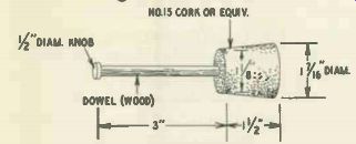
Fig. 723. A cork and a wood en dowel make a very suitable tube tapper.
The existence of a cathode-to-grid short is generally indicated by the inability of the brightness control to regulate brightness.
It will not be possible to reduce the excessive brightness present to normal levels when such a defect is present. Retrace lines will probably be seen and synchronization is likely to be impaired.
In many instances, the picture will be very weak or absent.
Arcing may sometimes be seen in the neck of the tube.
An appreciable difference in the grid-to-cathode voltage readings, when measurements are made with the picture tube in and out of its socket, indicate that a grid-to-cathode short may be present. To verify if this is the case, make a resistance check between the two electrodes with the tube disconnected from its socket. To check for a "hot" short, let the picture tube warm up by leaving the receiver on for five minutes or so; then turn the set off, disconnect the tube from its socket and quickly measure the resistance between grid and cathode. The ohmmeter section of a VTVM should be used for this test, with the meter set at its highest ohms range to permit detection of small amounts of leakage.
In many cases, a grid-to-cathode short can be eliminated. The possibility is particularly good if symptoms disappear momentarily when the base or neck of the picture tube is gently tapped.
One method of clearing up the short may be described as follows: Charge a 0.25 pf 600-volt capacitor to approximately 400 volts by connecting it between a suitable B-plus point and ground: Now connect the capacitor between the picture tube grid and cathode, leaving the receiver on. Repeat this discharge process several times.
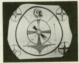
Fig. 724. This photo shows the effect on a test pattern when the metal cone
of a picture tube becomes magnetized.
When this method is ineffective, the receiver's high-voltage power supply may be used to "flash" out the short. To apply this technique, proceed as follows: Connect the grid pin of the picture tube to ground through a well-insulated clip. Attach a piece of high-voltage wire to the plate cap of the horizontal output tube. Terminate this wire in a well-insulated clip. Now turn the set on and touch the naked end of the clip to the cathode pin of the picture tube several times in succession, taking care to avoid shock. Gently tap the neck and base of the tube at the same time. The high-voltage arcing that takes place between the electrodes will often clear the short.
The lead going to the tube's 2nd anode is sometimes used as a source of high voltage for the flashing technique just described.
The possibility of damaging components in the high-voltage circuit becomes greater, however, when this method is employed.
Magnetized metal picture tube The metal cone of a metal-glass picture tube will become magnetized if a strong magnetic field is brought near it. Contact of the cone with the magnet of a PM speaker is the commonest cause of cone magnetization. The characteristic symptom produced is a distortion of the picture and raster. The raster's edges are generally twisted out of shape. (Fig. 724). Magnetization of the middle and small end of the cone tends to cause the severest distortion. The defect is readily identified with the aid of a pocket compass. The needle of the compass will deflect toward the magnetic area on the cone, when the compass is brought near the latter.
To demagnetize the cone, the following procedure may be used. Make up a coil of 1,250 turns of No. 24 copper wire, wound on a flat form with a diameter of 7 inches. Connect a line cord and plug to the ends of the coil and apply power (line voltage). Now move the flat side of the coil over the cone area to be demagnetized.
Power should not be applied continuously to the coil since the unit takes 1 ampere at 117 volts and will overheat if left on for a considerable length of time. Power should not be removed from the coil until it has been moved away from the cone. The back emf that develops when the line voltage is removed may otherwise re-magnetize the cone to a certain extent.
Universal picture tubes
A quick way to check on picture-tube performance is to use a picture tube that permits quick substitution. A universal picture tube, the 5AHP4, does not require a focus device or ion-trap magnet. To observe set performance it is necessary only to insert the universal tube in place of the regular picture tube and to connect the high-voltage lead and the regular picture-tube socket to the 5AHP4.
Another type that can be used for testing virtually any picture tube from 10 to 27 inches is the 8XP4. This tube is an 8 1/2 -inch rectangular unit featuring self-focusing and a parallel-mounted electron gun, eliminating the need for an ion-trap magnet. No external conductive coating is used.
The 8XP4 may be used in receivers designed for either magnetic or electrostatic focus to check almost any electromagnetically deflected picture tube, regardless of deflection angle.