In a number of instances the replacement of a tube in a television receiver can disturb normal operation. Inserting a new oscillator tube in the front end, for example, can compel realignment of the oscillator slugs. This disturbance of normal operation is particularly likely when one tube type is substituted for another.
Such substitutions merit the same serious thought that any other design change does.
Precautions in making tube substitutions
Sometimes one tube type can be substituted for another if a technician has satisfied himself that the pin connections are identical and that the voltage and current requirements are similar.
There are also some cases where tubes having widely different characteristics may be substituted in a given circuit. In the substitution of the 6BA6 for the 6AU6 you have tubes whose major differences are in their cutoff characteristics. The 6AU6 is a sharp cutoff pentode, the 6BA6 a remote-cutoff type. Other than this, in typical operation, their plate resistance, transconductance and plate current are reasonably close. This does not mean that substitution will necessarily work both ways. A remote-cutoff tube, on occasion, may give slightly inferior but acceptable performance in a circuit requiring a sharp-cutoff tube. However, a sharp cutoff unit will not usually perform well in a circuit requiring a wide grid-control range.
For optimum performance, try always to use exact tube replacements. Just because a substitution works well in one case, don't assume it will work equally well in others.
Salvaging the diode-triode
Sometimes the diode section of a dual-purpose tube will be defective but a tube-tester check will show that the triode portion of the tube is still in good condition. Do not discard the tube-keep it on hand with a label pasted on the tube to indicate its condition.
There are many FM and TV receivers that use only the triode section of the tube. In such applications the tube will be perfectly satisfactory.
Replacing tuner tubes
If a 6BQ7 tube is to be replaced, inspect carefully the tube that you intend to use. Some makes of 6BQ7 are of inferior design and tend to be very short-lived. The makes referred to have plates whose size is too small. The width of the plates in such tubes is be between 1/4 and 5/16 inch, compared to 3/8-inch plate width in a tube of satisfactory construction. As a further aid in identifying the inferior-make 6BQ7's, check the number of rivet holes in each plate. The better tubes have two such holes per plate; the inferior ones have only one. By the time these words appear in print, the likelihood of purchasing such inferior-make 6BQ7's ought to be fairly slim; the service technician should, nevertheless, keep his eyes open in purchasing as well as in replacing 6BQ7's, since the possibility of getting-and unwittingly using-one of these sub standard tubes will still exist. For purposes of comparison, keep an old satisfactory-make 6BQ7 tube handy.
The comments about plate size do not apply to 6BK7-A tubes.
These tubes have small plates, but this construction feature is normal for them.
6BQ7 tubes, when used in cascode tuners, have a tendency to develop heater-to-cathode shorts. The condition is due in large part to the operation of one of the two cathodes at a high positive potential with respect to the filament. When the cathode is, say, 135 volts positive with respect to the filament, a strong electro static pull is set up between these elements. Expansion of the filament due to the heat increases the effect of this pull. Because of the two forces just mentioned, the filament may finally butt its way through the cathode sheath; the resultant heater-to-cathode short makes the tube unusable. Substitution of a 6BQ7-A, which is an improved version of the 6BQ7, is recommended, to avoid recurrence of such a defect.
In some receivers you can improve reception by interchanging the 6CB6's used in the rf and converter stages even though a check in a tube tester will show the tubes to be about equal in quality.
Sometimes new tubes that check slightly better in the tube tester will not give this improvement. The tube that performs better is a so-called "hot" tube-one that has a very good noise figure. Often a tube with a good noise figure is used in the converter stage, where its benefits are not utilized to the extent that they would be in the rf amplifier circuit. In some cases, when a great improvement is noted in a receiver after switching front end tubes, it may be a sign that the front end is badly in need of alignment.
Some technicians keep a small stock of these hot tubes expressly for use in replacing 6CB6 rf amplifier tubes. It is a good idea to mark them for quick identification.
Every now and then a particular tube may not be readily avail able-generally when you need it most urgently. Sometimes a little ingenuity will solve the problem. In the case of 6BQ7-A and 6BZ7 tubes, a type 12AT7 can be used if you wish to take the time to make the conversion.
To make the substitution, tie pins 4 and 5 of the 12AT7 together and clip off pin 4 or 5, whichever one is grounded in the socket. This will place both halves of the 12AT7 heater in parallel.
Be certain the pin is clipped short enough to prevent it from going into the socket, as this would cause a short in the heater circuit.
Take care in tying the pins together as the glass of the tube is very easily broken. Also take care to plug the tube into the socket the right way, as it will fit two ways when pin 4 or 5 is clipped. This conversion will work with any set in which pin 9 of the 6BQ7-A tube socket and one side of the heater circuit are grounded.
Replacing rf oscillator tubes
If an rf oscillator tube is to be replaced in a TV receiver, try several tubes and select one which will produce the smallest shift in oscillator frequency, and thus avert the need for realignment of the oscillator slug. A reception check should be made on the high channels in such cases, since these are the settings at which the frequency shift is likely to be greatest.
In some cases, several oscillator tubes will have to be tried to obtain one which is capable of providing the proper injection voltage to the mixer. Insufficient injection voltage will produce a weaker picture (and possibly sound). Choose a tube which provides best picture and sound (as well as the least frequency shift). When a uhf oscillator is to be replaced, the service technician should he careful not to wiggle the tube back and forth during its removal or insertion. It should be pulled out or pushed in straight from the socket. Wiggling the tube may distort the socket contacts slightly; such a slight physical distortion can have a very marked adverse effect on the reception of uhf signals. The technician should keep in mind that the placement of parts and leads in uhf tuners is much more critical than it is in vhf front ends due to the extremely high frequencies at which the circuits operate.
When a crystal is replaced in the uhf tuner, exceptional care should be used to avoid changing lead dress and parts placement.
Some makes of oscillator tube may function better than others in TV tuners. Try different brands of tubes, in cases where the reception obtained after an oscillator tube replacement is not too satisfactory.
Video if tube replacements
Variations in tubes used in video if amplifiers may cause trouble when replacements are made. Where a tendency to overloading is present-due to the presence of receiver tubes with higher-than average gain, and strong incoming signals-a tube with average gain characteristics should be selected in preference to one with an above-average gain. Several tubes may have to be tried to eliminate any overload. The agc control may have to be reset after each substitution.
The e_c - i_b characteristic curve of some 6CB6 tubes used as video if amplifiers is not entirely linear in the section along which the tube is operated. Limiting may be produced when strong signals come in. The sync portion of the video if signal is likely to be compressed in such circumstances, leading to poor vertical and/or horizontal sync. The trouble just described can occur when a 6CB6 with a somewhat abnormal characteristic is used in the last video if stage; this is so because the signal input at this stage is larger than in any of the preceding if stages. Try several tubes when replacing 6CB6's in video if stages, leaving the one that provides the best reception in the circuit.
Alignment can be affected when a video if tube is replaced. An alignment check, plus a retouching of the adjustments when necessary, is recommended to put the receiver into optimum condition after a video if tube replacement.
Sweep and sync tube replacements
Early-make 6BL7-GT's have a tendency to develop grid emission and cause rolling when used as vertical oscillators. Later-make versions of this tube are less likely to introduce such trouble. The technician may sometimes unwittingly use a new, but inferior, early-make 6BL7-GT. To avoid the possibility of a callback, keep the set operating (preferably in its cabinet) for several hours after such a tube has been replaced, watching for symptoms of vertical rolling.
When a 6BQ6-GT (horizontal output tube) that has failed pre maturely is being replaced, it may be wise in some cases to substitute a 6BQ6-G. The two tubes are identical in all respects except for bulb size. Tubes with the suffix G have a larger surface than CT types and can radiate heat more efficiently; they there fore tend to operate at a lower bulb temperature. Temperature promoted defects are less likely to occur in G-type tubes. When physical space is not adequate, the substitution of a G for GT type is impractical.
In cases where certain flyback defects are present, substitution of a new horizontal output tube may restore normal receiver operation for a while. Technicians may replace several output tubes in succession over a period of time before they realize where the real fault lies. It would seem wise in these cases to test a suspect horizontal output tube in a normal receiver, before replacing it permanently. If the tube works in the normal set but not in the receiver under test, and if a new output tube restores the operation of the set being tested to normal, a defect in the flyback may be present and should be checked for with a flyback checker. It is assumed no other trouble can be found.
Many technicians tend to condemn new horizontal oscillator tubes on insufficient grounds. When a receiver fails to hold sync after a replacement of the oscillator tube or can't be made to hold sync by suitable adjustment of the horizontal hold control, the technician may deduce that the new tube is defective.
This deduction is often incorrect. The reason for the error lies in the rather critical nature of the horizontal oscillator circuit.
Differences in tube characteristics tend to affect the frequency of the horizontal oscillator. Any oscillator frequency adjustment present in the receiver should therefore be reset if replacement of the horizontal oscillator tube is followed by improper synchronization. These adjustments should be made so that the picture is in sync with the horizontal hold control set to its mid-position. If the hold is at an extreme clockwise or counterclockwise setting when the picture is brought into sync, a slight amount of aging in the replacement tube may necessitate another service call. With the hold control properly set enough range is present to provide for reasonable changes in tube characteristics. When a sweep circuit tube is replaced in a receiver which is to be used in a low-line-voltage location, it is wise to test set operation with a Variac or similar line-adjust unit. This permits a check of the tube's performance to be made at a line voltage comparable to the one under which it will operate in the set owner's home. A selection of new tubes may have to be tried to obtain adequate deflection at reduced line voltage.
Oscillator tubes
Some makes of 6U8 used as vertical oscillators provide appreciably less height than others. Try several brands when replacing a tube of this kind in a receiver where that last 1 / 4 inch of height is essential.
Some brands of 12AU7's used as combined horizontal oscillator and afc tubes tend to produce either a permanent bend in the picture or a bend that moves slowly up or down. This symptom is often due to leakage between the filament and some other element in the tube. Some tubes are worse than others with respect to the amount of leakage present. An entire run of tubes in a certain production may have this trouble to a marked extent. Try several makes of 12AU7 if such bending appears when the original tube is replaced.
Tube design
Significant for longer life was the changeover from the old press-stem construction to the newer button-stem construction.
In press-stem construction the base leads enter the tube through the glass stem in a straight line (Fig. 901). Lead wires are necessarily thin and there is a considerable distance between the base pins and the tube mount. In button-stem construction the leads go directly from the base pin through the glass into the tube mount, being arranged in a circle similar to that used in miniature tubes. This type of construction uses heavier and shorter leads, resulting in better heat transfer from inside the tube through the base pins. It also leaves more room between the top of the tube mount and the glass, which results in improved heat radiation.
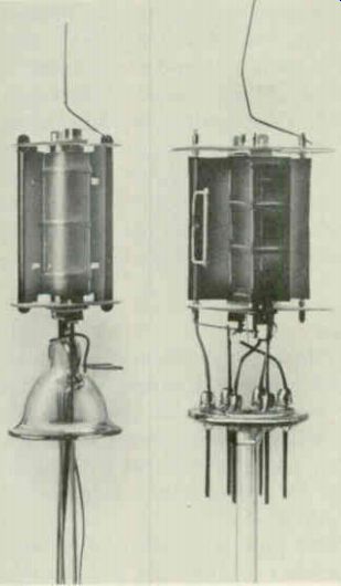
Fig. 901. Types of stem construction.
Other improvements to be found in today's tubes are larger and better grid heat radiators on the top of the tube mount. Keeping the grid cool reduces the possibility of grid emission and run away conditions. Large plate fins are also included to increase heat radiation from the plate area. Other refinements such as ribbed plates and one-piece beam-plate construction are some times added. The result is a more efficient deflection tube that operates at low plate supply voltages and gives satisfactory service in sweeping 90°-deflection-angle picture tubes of large screen size.
A few comparisons
By examining the voltage, current and wattage ratings of several popular deflection tubes, the capabilities of the various tubes may be compared. Types of the same family are pretty much identical but some withstand heat better than others and offer greater resistance to such abuse as misadjustment of the drive control.
Horizontal output tubes
There appears to be some confusion over the interchange ability of horizontal output tubes such as the 6BQ6-GT, 6CU6 and 6DQ6-A. These tubes appear to be almost exactly the same; many of them are even double-branded.
The difficulty here is that these tubes are interchangeable only unilaterally. That is, a 6CU6 can be used in place of a 6BQ6-GT and a 6DQ6-A can be used in place of a 6CU6, and not vice versa. In a great many instances, trying to use a 6DQ6-A as a replacement for the other two types results in excessive width which can not be sufficiently reduced. As a practical matter, replace with the tube the set has been designed for. If you want improvement, try using the sequence indicated above. In time the 6DQ6-A, which has closer tolerances than the 6CU6, will supersede the other two, but is should not be used indiscriminately as a replacement.
The first horizontal deflection tube, the 6BG6-G, could operate with a high plate supply voltage up to 700 and a relatively low zero-bias dc plate current of 180 ma. Next came the 6BQ6-GT rated at 550 volts plate supply and a maximum dc current beyond the zero-bias knee of 225 ma. Finally, following other intervening types, there is the 6DQ6-A with a zero-bias rating of 300 ma and a supply voltage of 600. Of course there are many other types which either upgrade electrical ratings or have mechanical improvements for better heat transfer. Notable in this respect is the 6CU6 which, though rated the same as the 6BQ6-GT, is improved for conservative operation, thus providing longer life.
Substitution rules In general, a different type should not be substituted for the original tube used in the set unless the original did not give satisfactory performance or service. For example, if the tube life is short or sweep is insufficient, substituting a tube with higher ratings or improved construction may prolong life. Substituting a more efficient tube for one of lesser efficiency may increase sweep width and high voltage.
If a more efficient tube is substituted, be sure to readjust the drive control to protect components and the damper tube and to insure that the picture-tube anode voltage does not go too high.
If substitution of a more efficient tube is not called for, the resulting sweep could be too great and be beyond range of adjustment, especially in receivers without a width control.
If the failure rate of the horizontal output tube is high but sweep is wide enough, substitute a more rugged tube with the same electrical characteristics, such as a 6CU6 for the 6BQ6-GT. If the sweep width is not sufficient-probably caused by component aging in the flyback circuit or lower B-plus supply voltage and other conditions in the set-then substitute a more efficient tube with higher zero-bias plate current and transconductance, such as 6DQ6-A for the 6CU6. If substitution fails to bring back the sweep to normal, it is time to suspect other components; the damper tube, horizontal oscillator, high-voltage rectifier, low-voltage rectifier or flyback transformer.
Substituting one type of horizontal output tube for another is fairly simple when the differences between types are fully under stood. As new tubes come out in the future, note the differences between these tubes and their predecessors; for instance, does the new tube have a larger glass envelope, does it have higher zero bias plate current or will it handle higher peak plate voltages? These pieces of information in addition to plate and screen dissipation, will tell you when to use the tube. Intelligent substitution should help the service dealer to reduce the number of call backs due to horizontal output tube failure. Remember, although a given receiver may have employed certain tubes that were avail able at the time it was designed, there is no reason why these same tubes should always be replaced in that receiver for the rest of its life. Tube manufacturers have improved the design of sweep tubes considerably over the years, through greater experience in manufacturing these types, and because of the demand of set manufacturers for higher performance tubes.
High- and low-voltage rectifier tubes
Before replacing a .high-voltage rectifier tube, make sure that the power is off, particularly when such a tube is located under the chassis. In the latter case, also short the corona ring to ground to be certain that no residual charge is left at high-voltage terminals with which you may come into contact.
When a 1B3-GT is to be replaced, check for continuity between pins 5 and 7 in the new tube. The presence of such a continuity reading indicates that an internal jumper exists between these pins.
If a component is present between contacts 5 and 7 on the socket (a top-of-socket resistance check will determine this), the jumper will short the component. Clip pin 5 off the tube base or use a brand of tube without a jumper, to avoid trouble in such cases.
In some makes of 1B3-GT, pins 3,5 and 8 or all the unused pins are internally connected to filament pins 2 and 7 to provide an internal anti-corona shield. Clip off all pins except 2 and 7 to avoid shorting any component when such a tube is used, unless the original tube has the same kind of anti-corona shield (as deter mined by resistance checks at the prongs). If one of two low-voltage rectifiers connected in parallel requires replacement, change the other one as well to avoid imposing too great a load on the new tube and shortening its life. The same procedure is recommended in cases where one of two high-voltage rectifier tubes in a voltage-doubler circuit has become defective.
6AX5-GT's used as low-voltage rectifiers have exhibited tendencies to lose emission prematurely. Replace this type of tube with a 6X5-GT, with which it is interchangeable.
Avoiding needless picture-tube replacements
Before condemning a picture tube as too weak for further use, check its filament voltage. When an aging tube's filament voltage has dropped even as little as 3/4 volt, the emission loss will be considerable. Check for poorly soldered filament prongs on the tube since this is one possible source of the trouble. If the fault is due to reduced efficiency in the power transformer, an inexpensive filament transformer may be used to provide the full 6.3 volts to the tube and prolong its useful life.
Re-necked picture tubes
The presence of a slight bulge or indentation in the neck of a new picture tube is no cause for concern. Service technicians sometimes feel that such eccentricities in shape indicate that the tube has been re-necked and is therefore not of first quality. The suspicion about the tubes having been given a new neck may be quite correct; the quality of the tube, however, is not impaired.
Re-necking may be necessary when a bulb neck is broken by rough handling or bumps suffered while the tube is on a production line. It is also performed when some inner part of the tube is substandard (although its bulb is not). The bulb or bell of the tube can be and is used again; re-necking is, however, necessary, since the neck was cut off to remove the gun and wipe away the screen coating.
Many other reasons besides the ones cited may necessitate re necking of a tube. Inasmuch as the process does not affect picture tube quality, performance or life, the service technician need not fret over visible signs of it in a tube that he intends using as a replacement.
Electrostatic-focus picture-tube substitutions
High-voltage electrostatic-focus picture tubes never became popular or widely used because low-voltage types that require less expensive circuitry were soon developed. Where substitution of a low-voltage for a high-voltage type is necessary, due, say, to the scarce supply of the latter, the following procedures can be used:
1. Choose a suitable replacement tube.
2. Disable the focus voltage supply since it will no longer be needed. (Use caution in working on this supply; terminals on it are at a potential of several thousand volts with respect to the chassis when the set is on.) Remove the focus voltage rectifier tube, and disconnect the wire leading from the focus electrode (socket contact 6) to the high-voltage focus supply. Connect a wire from socket contact 6 (at the chassis terminal post to which it leads) to. a variable source of B-voltage. Insertion of a potentiometer between socket contact 10 and ground permits the proper amount of focus voltage to be tapped off.
Before adjusting the potentiometer, the setting of the ion magnet, brightness and contrast controls should be checked to make sure they are correct. Since the focus changes produced by potentiometer manipulation are very gradual, it may be necessary to move the pot quickly through large angles of rotation, to note changes in focus and determine the optimum focus setting.
Once the proper focus voltage has been set up, no further adjustment should be required during the tube's life.
Retaining salvage value of the picture tube
Picture-tube manufacturers will not make any allowances on old picture tubes turned in under exchange plans if the tube face has been scratched. Technicians sometimes make a notation in crayon or with a china pencil on the face of an old tube, indicating its condition. These markings are, in some cases, hard enough to scratch the tube face. In other instances, the pencils used react chemically with the tube face, producing an etching on this sur face and injuring it. Defacement of the surface in such ways may destroy the tube's salvage value.
Don't use an abrasive type cleaner on the face of the picture tube or any other of its surfaces-use a mild detergent or soap, if needed.
Any scratch on the glass which is deep enough to catch a finger nail drawn at a right angle across the scratch will generally make the tube unacceptable to the manufacturer. In the case of frosted face tubes, the requirements are even stricter-any scratch, mark or blemish that remains after a soap and water cleaning will make the tube ineligible for an exchange allowance.
To check the condition of the tube, illuminate it with a light bulb of 60 watts or larger about a foot away from the tube.
Cracked and chipped sections, most likely to be found on the outer edges of the faceplate, will, in some cases, be visible as mirror like slivers or lines; in others, they will have star shapes. Rainbow colors, due to the refraction of incident light by the broken surface, will also call attention to the cracked or chipped areas.
Miscellaneous tube replacement notes
TV service technicians will find considerable differences in the quality of tubes made by different manufacturers. It will prove profitable to check the performance of various makes of tubes in different receiver circuits and thus become familiar with good, bad and indifferent brands.
Economy can often be promoted by switching identical types of tube from one section of the receiver to another. A tube that performs poorly in one stage, where circuit tolerances are critical, may do much better in another stage in which the requirements are not quite so strict. A I2AU7, for instance, that has lost a slight amount of emission-too much to perform satisfactorily as a horizontal oscillator-may work well in the vertical deflection circuit.