AMAZON multi-meters discounts
AMAZON oscilloscope discounts
THE circuits gathered together in this section are those which do not fit logically into the subject matter of the preceding sections but are important enough to be included in this guide. Their appearance at the end of the guide certainly does not imply that they are superfluous.
Here, more than in examining the other sections, a reader might discover that his peculiar needs have not been satisfied. It should be acknowledged, however, that many of the circuits we would like to transistorize do not yet lend themselves favorably to this modification. The author has tried to avoid those devices which in the present state of the art are mere laboratory curiosities. Such circuits might be reproduced ad infinitum but to the assured disservice of the reader.
Additional practical applications of transistor circuitry may be expected to appear with regularity in the periodical literature and the best of these ideas undoubtedly will find their way into future editions of this guide.
Simple Geiger counter
Fig. 1101 shows the circuit of a miniature Geiger counter employing a 1B85, 900-volt G-M tube and a two-stage transistor of amplifier. This arrangement has excellent sensitivity.
The 900-volt dc polarizing potential for the counter tube is sup plied by three miniature 300-volt batteries B1, B2, B3 (Burgess U200 or RCA VS093) connected in series. A 300-volt counter tube, such as type 1B86, also may be used in this circuit with one of the 300-volt batteries. Somewhat less sensitivity is obtained with this arrangement, however.
CAUTION: The 900-volt battery can deliver a dangerous electric shock. Use extraordinary care when working with this circuit.
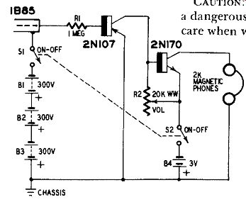
Fig. 1101. Simple Geiger counter.
Output pulses from the counter tube are amplified by the direct coupled amplifier employing a p-n-p transistor (General Electric. 2N107) in the first stage and an n-p-n transistor (General Electric 2N170) in the second stage for single-battery (B4) operation.
Geiger counter with transistorized high-voltage supply
In the Geiger counter circuit shown in Fig. 1102 the counter-tube dc supply is a transistorized oscillator (employing a General Electric 2N107 transistor) with a miniature stepup transformer.
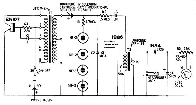
Fig. 1102. Geiger counter with transistorized high-voltage supply.
This dc supply, described originally by Thomas G. Knight (RA DIO-ELECTRONICS Magazine , September, 1956) converts the 6-volt battery potential to 300 volts of regulated dc for the 1B86 counter tube. It does this by using the 6 volts as collector bias for the transistor in a Hartley type oscillator in which the primary winding of the miniature transformer T1 is the tapped feedback coil required by this type of circuit. The oscillation sets up a high ac voltage across the secondary winding and this ac is rectified by a high-voltage cartridge type selenium rectifier RECT and filtered by capacitor C2. A compact voltage regulator is formed by the four series-connected NE-2 neon lamps and resistor R1.
Output pulses from the counter tube are delivered to the indicator circuit by the coupling transformer T2. Headphones may be plugged into jack J for aural indications. The 1N34 germanium diode rectifies the pulses and the resultant direct current deflects the 0-20 dc microammeter M for visual indications. By limiting the direct current through the meter, rheostat R3 serves as a RANGE control.
Phono oscillator
Fig. 1103 shows the circuit of a simple phonograph oscillator employing a single rf transistor (Raytheon 2N112) . This circuit may be fix-tuned to any frequency in the broadcast band and is operated directly into the antenna and ground terminals of a radio receiver tuned to a clear channel.
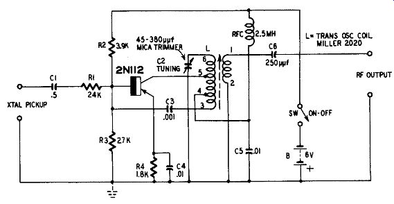
Fig. 1103. Phono oscillator.
A self-excited Hartley type oscillator circuit is used. The tapped oscillator coil assembly L is a conventional component (Miller 2020) . The number symbols appearing on this coil in Fig 1103 correspond to the manufacturer's coding and the coil must be connected as shown by these numbers, otherwise oscillation will not be obtained. Tuning is accomplished by means of a 45-380-Rd compression-type mica trimmer capacitor C2 and the screw-adjusted slug in coil L.
The oscillator may be modulated directly by a crystal-type phono graph pickup connected to the CRYSTAL PICKUP terminals. A trans former-coupled preamplifier will be required for a reluctance-type pickup. Suitable amplifier circuits may be found in Section 1.
While maximum signal transfer will be obtained by connecting the Kr OUTPUT terminals of the phono oscillator to the antenna and ground input terminals of the receiver, a sensitive receiver does not need this direct coupling. In this instance, a strong signal will be transmitted across a room from a short length of wire hung as an antenna from the top RF OUTPUT terminal.
Wireless microphone
This phono oscillator circuit has been modified (Fig. 1104) for use as a wireless microphone. This simple device may be used to "broadcast" into nearby radio receivers.
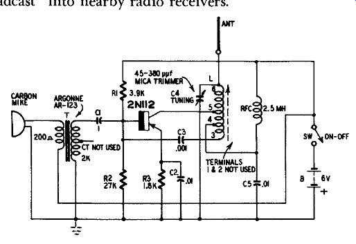
Fig. 1104. Wireless microphone.
Like the previous circuit, this arrangement uses a single rf transistor (Raytheon 2N112) in a Hartley type oscillator. Oscillator coil L must be connected exactly as shown in Fig. 1104 according to the manufacturer's number coding, otherwise oscillation will not be obtained. The output coupling coil (terminals 1 and 2) is not used in this circuit.
Tuning to any clear spot in the broadcast band is accomplished by means of the compression type mica trimmer capacitor C4 and the screw-adjusted tuning slug in coil L.
A short vertical rod or whip antenna is sufficient for the short range transmission permissible with this type of device. Good results have been obtained with a 2-foot length of No. 12 bare copper wire.
The carbon microphone MIKE is operated from the same 6-volt battery B that supplies the dc bias for the transistor. The battery may be four 1.5-volt flashlight cells connected in series.
Photoelectric intrusion alarm 1 Fig. 1105 shows the circuit of a simple light-operated intrusion alarm employing semiconductor components throughout. The electric eye is a selenium photocell PC, the relay amplifier employs a transistor (Raytheon CK722) and the power supply uses two 1N34 germanium diodes.
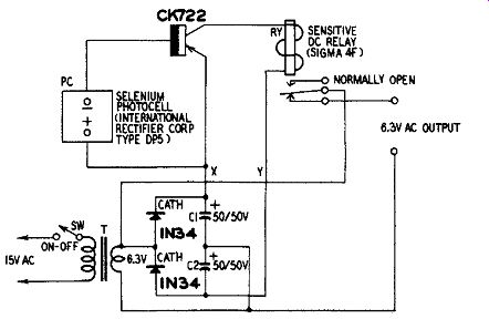
Fig. 1105. Photoelectric intrusion alarm.
As long as the photocell is illuminated by a light beam, the armature of relay RY is pulled away from the lower contact and the circuit to the output terminals is broken. When the cell is darkened, as when the light beam is interrupted by a person passing between the light source and the cell, the armature is released and returns to the lower contact, closing the output circuit. This applies 6.3 volts ac from transformer T to the output terminals, and this voltage may be used to operate a bell, horn or other alarm device. The circuit is fast-operating and will work when the cell is illuminated from an incandescent lamp or by daylight. An appropriate lens in front of the cell will concentrate the light rays for increased sensitivity.
Dc operating voltage for the transistor, is furnished by a simple voltage-doubler type of power supply consisting of the 6.3-volt 1-ampere filament transformer T, two 1N34 germanium diodes and two 50-0 50-volt electrolytic capacitors C1 and C2. With 115 volts ac input, the dc output voltage of this power supply under full load is 17.5.
Battery operation may be employed if this is desired. Simply omit C1, C2, T and the 1N34's and connect a single 22.5-volt battery to leads X and Y. Connect the positive terminal of the battery to X and the negative to Y. Connect the ON-OFF switch SW in series with lead Y and the battery.
The dc relay is a Sigma type 4-F. This relay normally closes on 1.6 ma but can be adjusted to operate on currents as low as 1 ma by unscrewing its pivot screw a small amount.
Transistorized 0.6-watt intercom
Operated from a single 12-volt battery, the intercom unit of Fig. 1106 provides an audio power output of better than 0.5 watt.
The high output is provided by a class-A amplifier employing a power transistor ( Sylvania 2N102) . The high-gain input amplifier stage uses a conventional transistor ( Sylvania 2N35).
T1, primary impedance (as per diagram) 3 ohms, secondary (in circuit) 2,500 ohms (Merit A-2900, Stancor A-3823 universal output types, or equivalent); 12, primary impedance 12,000 ohms, secondary 32 ohms (same type as T1); 13, primary impedance 100 ohms at 150 ma, secondary 3.2 ohms (Acme 1-24041).
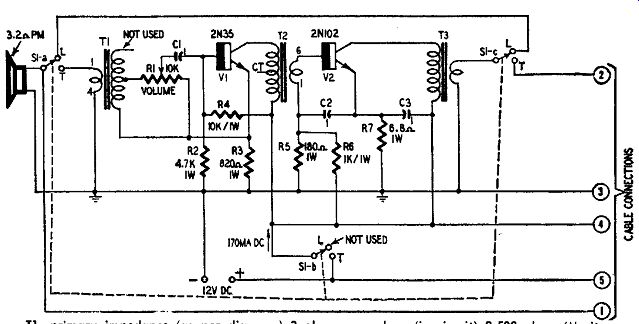
Fig. 1106. 0.6-watt intercom.
While the class-A collector direct current of the 2N102 (150 ma) might appear high, this drain is present only during the relatively short intervals when the intercom is in operation. No current what ever is drawn during standby periods. In a tube-type intercom, 150 ma would be drawn continuously by the filaments alone. Eight 1.5-volt size-D flashlight cells connected in series will power this circuit for over 1 month on a 2-hour-per-day continuous basis which is much more extreme than the actual intermittent operation demanded of an intercom. Economical battery operation makes the unit completely portable and divorces it from power-line complications.
The small PM dynamic speaker serves as a microphone when transmitting and as a loudspeaker when listening. A 3- or 4-inch speaker is adequate. The transmit-receive changeover is handled by the three-pole two-position lever switch S1 (Centralab 1457 with one section unused) . This switch rests normally in its LISTEN (L) position where S1-a and S 1-c connect the output transformer to the speaker. In the TALK position, S1-c disconnects the speaker from the amplifier output and SI-a connects it as a dynamic micro phone to the amplifier input.
Fig. 1107 shows how two intercom units may be connected together with a five-wire cable. Changeover switch S1 at each station rests in its LISTEN position, rendering both intercom units dead.
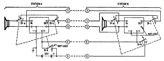
Fig. 1107. Typical two-station intercom installation.
Section S1-b of either switch, however, closes the battery circuit to both amplifiers when the switch is in its TALK position. When station A is transmitting, its loudspeaker is switched to the amplifier input as a microphone; at station B, the speaker is at the amplifier output and the output from Station A is applied to the input at station B. Battery voltage is applied to both units. Thus, A talks and B listens. When station B is transmitting, the opposite set of conditions results.
The circled numbers in Fig. 1107 refer to terminals of the cable plug and to cable leads. No. 1 at station A is connected to No. 2 of station B, 2 to 1, 3 to 3, 4 to 4 and 5 to 5. Additional stations may be connected by running No. 1 of station A to No. 2 of the new station, 2 to 1, 3 to 3, 4 to 4 and 5 to 5. With this arrangement, any station can communicate with any other station.
Fig. 1108 shows a simpler though less effective system for short-distance operation. Here only one intercom amplifier is used and the remote installation (station B) consists only of a loudspeaker and changeover switch. The switches at each station in this setup are of the double-pole double-throw type. When station A is transmitting, speaker A becomes the microphone and speaker B is switched to the output circuit of the amplifier. When station B is transmitting, speaker B is switched to the amplifier input to serve as the microphone while speaker A is transferred to the amplifier output.
In either of the installations (Fig. 1107 or 1108) , only one battery is needed and can be installed at any of the stations which is most convenient.
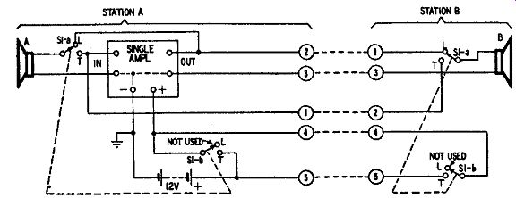
Fig. 1108. Economy two-station short-distance installation.
Hearing aid
Fig. 1109 shows the circuit of a hearing aid having good sensitivity and output. The three-stage amplifier in this unit employs a low-noise transistor (Raytheon CK727) in the input stage and high-alpha units (Raytheon CK721) in the intermediate and output stages. Transformer coupling is used for maximum overall power gain.
Readily obtainable subminiature components are employed throughout. Switch SW is integral with the specified VOLUME CONTROL potentiometer R4. The low-impedance microphone is connected directly into the base-emitter input circuit of the first transistor and, similarly, the magnetic earpiece is connected directly into the collector circuit of the output transistor.
The dc drain from the 1.5-volt cell B is approximately 2.35 ma.
Bias stabilization is supplied by voltage-divider networks R2-R3 and R7-R8. Some adjustment of resistance R9 may be necessary for maximum output vs minimum distortion.
Diode-type transistor power supplies
Because of the low current drain of conventional transistors, germanium diodes may be employed as rectifiers in ac-line-operated power supplies used to furnish dc to these transistors when battery operation is not desired. Because of the low voltage requirements of transistors, such power supplies may employ small filament trans formers. It is a simple matter to connect diodes and capacitors together to form voltage-multiplier circuits when the required dc voltage is higher than the rms voltage of the filament winding of the transformer.
Fig. 1110 shows several power supply circuits employing a filament transformer, diodes and capacitors. In each circuit, T is a 1-ampere 6.3-volt transformer. The dc output characteristics (for an ac input of 117 volts rms) are shown by the curves in Fig. 1111.
These circuits will be satisfactory as they appear in Fig. 1110 for most low-drain circuits using one or two transistors operated at fixed voltages. For better voltage regulation (less fall-off of voltage as the dc output current increases) and higher output current (such as will be required for multistage transistor circuits containing bias resistor networks) , General Electric type 1N91 miniature germanium power rectifiers may be substituted for the 1N34 diodes and the capacitor values increased. A 1N91 in the simple half-wave circuit (Fig. 1110-a) with C equal to 100 for example, gives 60 ma output at 6.3 volts dc contrasted to the 5 ma at 6.3 volts obtained with the 1N34 and 10 uf.
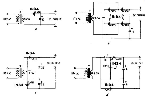
Fig. 1110 (a toe). Diode-type transistor power supplies. (a) Half-wave.
(b) Bridge.
(c) Voltage doubler.
(d) Voltage tripler.
(e) Voltage quadrupler.
Safety diode for transistor circuits
Accidentally reversing the battery in transistorized equipment often means quick and complete ruin of the transistors. Unless an operator is on the alert constantly, this mistake is almost inevitable.
In most transistorized devices, such accidents can be prevented simply by connecting a germanium or silicon-junction diode in series with one of the dc input terminals of the device (Fig. 1112-a) .
The diode acts as a polarity-sensitive switch which acts instantaneously and requires neither attention nor adjustment.
The diode is poled so that only an extremely small current flows when the battery is reversed. This current is too minute to damage the transistors. As shown in Figure 1112-a, the anode of the diode is connected to the positive dc terminal. This polarity allows high forward current to flow through the diode to the circuit. When the battery is reversed, however, the anode becomes polarized negative...

Fig. 1111. Performance of diode-type power supplies.
...and the diode resistance increases-often several thousand times higher than the forward resistance. The tiny reverse current passed by the diode in this condition can cause no damage to the transistors.
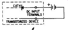
Fig. 1112. Diode protector for transistor circuits.
Total Current Drain
Voltage Loss due to Diode 20 µa 0.05 100 µa 0.10 200 µa 0.15 500 µa 0.22 1 ma 0.30 2 ma 0.40 3 ma 0.50 4 ma 0.60 5 ma 0.65 10 ma 0.90 20 ma 2.0 30 ma 2.5 40 ma 3.1 50 ma 6 4.0
The natural internal resistance of the diode causes a voltage drop across the diode when the latter is carrying current. The voltage at the transistor circuit therefore is somewhat less than the battery voltage and is equal to the battery voltage minus the diode voltage drop. When this voltage drop is appreciable, the battery voltage may be boosted by this amount to offset the loss. Figure 1112-b shows the approximate voltage lost across a 1N34 diode at various common transistor currents. The loss will be lower with low-resistance diodes, such as type 1N455, and with gold-bonded types.
The safety-diode scheme usually is unsatisfactory in class-B amplifiers because the collector current in these circuits swings (on signal excitation) from a few microamperes up to several milli amperes. The diode loss accordingly is both large and fluctuating and it will reduce power output and increase distortion of the class B amplifier.
REFERENCES
1 Transistorized Photocell Alarm, RADIO-ELECTRONICS Magazine, December, 1955; p. 40.
2 Build This Transistorized Intercom With 0.6-Watt Output, RA DIO-ELECTRONICS Magazine, July, 1956; p. 48.
Diode Rectifier Supplies, Popular Electronics, January, 1956; p. 58.
4 Safety Diode Protects Transistors, Radio R.: Television News, March, 1956; p. 146.
* Author is Rufus P. Turner.