A NETWORK is a circuit made up of two or more components--resistors, capacitors, inductors or the mutual inductance between two inductors. These component parts of the network are called elements or parameters.
When the parameters are constant and independent of the cur rent through them, the network is said to be linear. If any of the parameters are nonlinear, (such as amplifying tubes, iron-cored inductors, electrolytic capacitors, barretters, glow lamps, thermistors) the network is nonlinear.
If there is no source of energy within the network, it is said to be passive; if the network contains any sort of generator, it is called an active network.
If the network has only two points at which power can be applied, such as the three diagrams in Fig. 801, it is called a two-terminal network; if it has four, i.e: has an input and an output, as in the examples of Fig. 802, it is referred to as a four terminal network.
Even a simple potentiometer or volume control is a four terminal network, for the circuit of Fig. 802-b can have the upper right-hand resistor omitted and the junction of the other two is clearly the tapping point of the potentiometer. Circuits a and b of Fig. 801 will be recognized as, for example, the cathode resistor and bypass capacitor in an audio amplifier and a variable treble cut, connected between plate and ground of an amplifying tube. The circuit of Fig. 802-a is typically an intermediate-frequency transformer in a superheterodyne receiver, and the mutual inductance between the two inductors is one parameter of the network.
Transducers

Figs. 801-a,-b,-c. Various arrangements for two terminal networks.

Figs. 802-a,-b,-c. Four-terminal networks.
A four-terminal network is equivalent to a transmission system and has an optimum input and output load. Such a system is sometimes called a transducer, for example, when the term is applied to a phonograph pickup or a loudspeaker. Although these devices have only two apparent terminals their equivalent circuits can be drawn in the form of a four-terminal transmission system.
If the network is purely resistive--that is, made up of non inductive non-capacitive linear resistors--its behavior is constant for dc or ac of any frequency and the impedance of the network is the same as its resistance. With the introduction of capacitance or inductance, the reactance of the parameters, whose value is a function of the frequency of the applied voltage or current, means that the impedance of the network must be evaluated by Ohm's law for ac. All reactive networks are filters in a sense because a filter is a circuit which discriminates between different frequencies. Filters are designed to do certain types of discrimination and are conveniently divided into four groups.
Filters
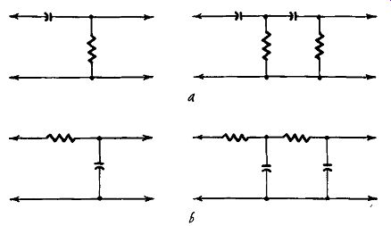
Figs. 803-a,-b. Single-section and two-section high-pass and low-pass
filters. A low-pass filter is one which transmits all low frequencies
up to a specified limit and then attenuates frequencies higher than that.
A high-pass filter is one which attenuates all frequencies below a specified
limit while passing on without change those above it. A bandpass filter
passes a specified band of frequencies without change while attenuating
all frequencies below and above the specified band. A trap filter attenuates
a specified band of frequencies while passing on those above and below
the specified band. By these definitions, a treble-cutting device is
a low-pass filter; a bass-cutting control is a high-pass filter; the
device which would produce a response of the curve of Fig. 715 is a bandpass
filter and a scratch or heterodyne whistle filter is a trap filter.
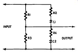
Fig. 804. Basic tone control circuit.
Since a purely resistive network does not discriminate between frequencies, it is obvious that modification of the response of an amplifier with respect to frequency cannot be done by purely resistive methods; these are restricted to control of input or output regardless of frequency. Modification of the response with respect to frequency involves the use of capacitance or inductance or both, usually with resistance, to modify the effect of the impedances of the reactive parameters. For most purposes of tone control it is theoretically immaterial whether capacitors or inductors are use(!. The practical choice is usually capacitors because they are cheaper and much less liable to pick up hum; they are also more compact. But phase change occurs when either capacitors or inductors are used, the phase change with an inductor being the reverse of that with a capacitor.
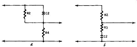
Figs. 805-a,-b. Tone control circuits: a) bass cut; b) treble cut.
Attenuation and boosting Confusion is sometimes caused by incorrect use of the term "boosting". One hears frequently of treble or bass boost but on examination it is found that that which is called boosting is nothing of the sort. To boost infers that something has been given a push, as it were. A high-pass filter is not a treble booster since it operates by cutting the bass. If, for some specified purpose, the treble must be emphasized, then it can be done only by employing an additional stage of amplification and wasting the bass that could be amplified by that stage-but no frequencies have been boosted. Genuine boosting can be achieved, of course, in some such way as replacing the resistive load of an amplifying tube by a load consisting of an inductor tuned by a capacitor.
According to the values selected, the circuit will have a maximum impedance at its resonant frequency; this impedance may have a value which gives the maximum amplification from the tube but it may not be the value which gives the minimum distortion.
The actual value of impedance and the sharpness of resonance naturally depend on the Q of the circuit, and in a radio frequency amplifier it is often desirable that the Q should be as great as possible. On the other hand a sharp resonance in an audio amplifier is usually very objectionable; the Q can be lowered by shunting the tuned circuit with a resistor.
It is generally the aim of an audio designer to construct an amplifier with as flat a response as possible so tuned L-C circuits are not used except in such specialized applications as neutralizing a dip in the response of a speaker or providing a trap filter for needle scratch, caused by some resonance in the pickup system, (always excepting, of course, L and C components in filters and attenuators). Accordingly, the tone control in an amplifier is nearly always of the untuned type and so is not boosting in the literal sense. There is, however, a loose convention that an amplifying tube in association with a high or low-pass filter is called a booster since the tube is a generator.
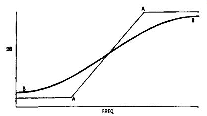
Fig. 806. Ideal and practical attenuation curves: AA) ideal characteristic;
BB) actual characteristic of an R-C filter. The slope of AA is 6 db per
octave.
The rate of attenuation in a simple high-pass or low-pass filter is 6 db per octave, two frequencies an octave apart having a frequency ratio of 2:1. If a steeper cut than this is required, then the filter must have two or more sections; each section will cut at the rate of 6 db per octave, and for a perpendicular cut in the response ...
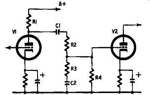
Fig, 807. Active low-pass filter provided by two tubes and associated
networks.
... an infinite number of sections would be required. Fig. 803 shows simple and two-section high-pass and low-pass filters. The first circuit of Fig. 803-a can be understood to represent the coupling capacitor and following grid resistor of an R-C coupled amplifier.
Any alteration in value of the coupling capacitor can have no effect on the actual slope of attenuation; it can merely move the attenuation higher up or lower down the frequency scale of the amplifier. An amplifying tube can separate the two sections of the filter in the second circuit. Similar considerations apply to the circuits in Fig. 803.
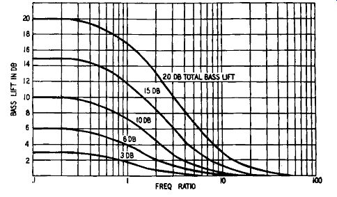
Fig. 808. Response curves of the filter shown in Fig. 807 for different
degrees of amplification.
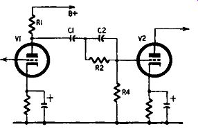
Fig. 809. Active high-pass filter provided by two tubes and associated
networks.
The basic circuit for all tone-control circuits employing resistance and capacitance is given in Fig. 804. The values of the components may vary between zero and infinity, these limits being the equivalent of short- or open-circuiting any of the components.
Applying this to the elimination of certain components produces the circuits of Fig. 805 which show bass- and treble-cut circuits. A simple rule to determine the purpose of any network is to remember that a series capacitor will not pass low frequencies if it is of small capacitance, nor will a small shunt capacitor short-circuit low frequencies. The capacitor of Fig. 805--a is in series between input and output of the filter; in Fig. 805-b it is shunted across input and output.
In view of what has already been stated as to the 6 db slope produced by a capacitor it might be thought that the circuits of Fig. 805 will give that degree of attenuation; in practice they do not.
In Fig. 806, the response AA, having a slope of 6 db per octave, is what would be obtained ideally by the circuit of Fig. 805-a. In practice what one gets is a response shown by BB, at no point of which is the gradient as steep as 6 db per octave. The circuits of Fig. 805 are of no value without associated amplifying tubes and these provide the terminal impedances of the networks. Obviously
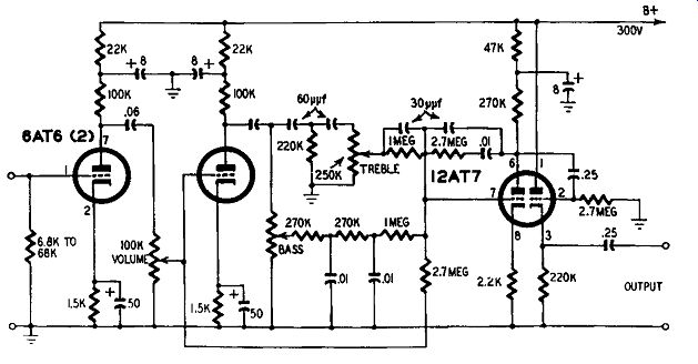
Fig. 810. Tone-control amplifier giving smooth control of bass and treble.
the terminal impedances, being part of the filter, have a bearing on its behavior, and as the terminal impedances will necessarily vary ...
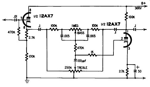
Fig. 811. Simple tone-control amplifier.
... with frequency as with the types of tubes used and their parameters, the design of the filter must take into account the types of tubes used and the conditions under which they are operated.
Fig. 807 shows two tubes and associated networks to provide an active low-pass filter. This, as has already been explained, is usually called bass boosting, but as the boost is obtained by non-amplification of higher frequencies, it is desirable to call the circuit what it is. R1 is the plate load of the first tube and is in parallel with the internal plate impedance of the tube, with the series net work R2-R3-C2, and the second tube's grid resistor R4. The value ...
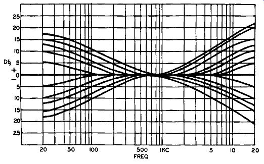
Fig. R12. Response curves of the tone-control amplifier shown in Fig.
811.
... of R1 is determined by the tube selected for the first amplifying stage; that of R4 must not exceed the grid-cathode resistance specified for the second tube.
The impedance of C2 decreases as frequency rises, so acting as a partial short circuit to ground. R4 should be many times the value of R3 (at least 20 times) otherwise it will act as a short across the circuit R3-C2. C1 is selected to give adequate bass response, as detailed in earlier sections, but may be chosen to give bass attenuation below those frequencies it is desired to pass through the filter. The reactance of C1 is assumed to be very small as compared with R4. It may happen, however, that the combined impedances of C1, R3 and C2 are so low that, being shunted across the plate load R1, they cause distortion through inadequate load on the tube; this is counteracted by inserting R2. If the first stage is required to deliver only a small output it may be omitted, but the value of R4 must not be less than twice the plate resistance of the first tube; for higher outputs and when R4 is not high enough R2 must be included. This point is mentioned because it is frequently omitted in published tone-control circuits when its presence is essential, which results in a tedious hunt for distortion that ought not to be there. R2 has the further advantage of improving the ratio between bass and treble.
The amount of boost is a direct function of the equivalent values in the circuits of Fig. 805. It will be noticed that the slope of the curves in db per octave is a function of the total boost. In Fig. 806 the point where curves AA and BB intersect is mid frequency, and this is where the slope is defined. Curve AA is shown with a slope of 6 db per octave between the limit frequencies, but the practical curve BB only reaches its maximum ...
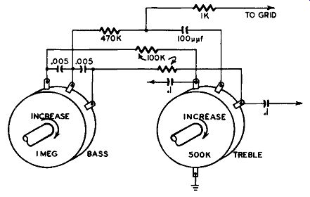
Fig. 813. Construction details of the center section of the tone-control
amplifier shown in Fig. 811.
... slope at the mid-frequency. In Fig. 808 the family of curves has the following maximum slopes:
Total bass lift (db): 3 6 10 15 20
Slope at mid-frequency
(db/octave): I 2 3 4 5
The horizontal axis of Fig. 808 is described as the frequency ratio; the curves can be moved to the left or right by altering the value of C2. The amount of bass compensation can be varied by shunting C2 with a variable resistor.
The companion circuit to Fig. 807, this time for an active high pass filter, is shown in Fig. 809, and, by suitable choice of components a set of curves can be drawn which are a reversal of those shown in Fig. 808. As before, altering the value of C2 moves the curves to the left or right; the amount of treble gain can be varied either by changing R2 or inserting a variable resistor in series with C2 and the junction of R2 and R4.
Scattered through technical handbooks and magazines are a host of circuits giving continuously or stepped variable combined bass and treble controls. These differ in complexity and behavior, although the final result is almost always satisfactory. Nothing would be gained by reproducing these various tone-control amplifiers, which is what they really are, but the writer submits Fig. 810 as a design which he has used with great satisfaction for a number of years. This gives a very smooth control of bass and treble and is particularly suitable for the proper compensation of various phonograph recording characteristics as well as improving the response of broadcast transmissions. The incorporation of a cathode-follower output enables the amplifier to be constructed as a separate unit and used fairly remotely from the main amplifier.
Another circuit, originally described by P. J. Baxendall (Wire less World, October, 1952) and further dealt with by B.T. Barber (Audio Engineering, September, 1953) is shown in Fig. 811. It has the merit of greater simplicity and a somewhat greater amount of available control. This can be assembled into a very small unit through the introduction of a combined component embracing the whole center network (Centralab's Junior Compentrol C3-300). The writer has found the circuit of Fig. 811 very convenient indeed both as to capabilities and compactness.
The response curves of Fig. 812 illustrate the wide range of control which the circuit makes available. Fig. 813 shows the construction detail of the center section of the control amplifier when the Compentrol is not used.