PEOPLE can be rather strange. We pride ourselves on being logical, and then, time after time, we fail to follow a techno logical advance to its logical conclusion. A fairly good example of this was the early development of the automobile. Remember those photographs of the first cars? They took the "surrey with the fringe on top," got old Dobbin off the front of it, cut him down in size and put him on the inside, leaving the remainder of the carriage just about as it had been before. They even called the thing a "Horseless Carriage." In those days, they didn't seem to realize that they were dealing with something that was essentially new and should be designed new from the ground up.
In many ways, the contemporary hi-fi system is about as different from the radio and radio-phonograph of a few years ago as the internal combustion engine was from old Dobbin. Possibly this is why a good many people who have been trying to put hi-fi systems into a housing equivalent to the "surrey with the fringe on top" have been dissatisfied with the results.
To carry the analogy a little further, both the automobile and the "one-horse shay" had the same original basic purpose-getting people and things from one place to another. But through development and refinement, the automobile became transformed into a completely new object that does a far better, faster and more comfortable job of transportation than would ever have been possible with the "one-horse shay." Similarly, the basic purposes of the older radios and phonographs were the same as that of present-day hi-fi-the transmission of a sound from one place to another. But here the parallel ends.
High-fidelity is the result of continuous advances in the science of electronics and ever present refinements in the art of audio reproduction. But, as in all arts, the final word has not been said.
One of the areas where considerable refinement must still occur lies in that of the furniture in which the equipment is housed.
After all, you've probably spent a good deal of time, effort and money in making a pleasant and comfortable living room, and you are therefore understandably reluctant to admit a Franken stein's monster to a permanent place in it. Before you can intelligently decide what kind of furniture you want to put into your living room to house the hi-fi set, you must first examine the system itself to see what it requires in the way of space. To exhume an old cliche, "You can't put a quart in a pint bottle." So, let's take a look at the equipment and see how big a bottle you do need.
I shall not discuss the relative merits of different kinds or makes of equipment; a tremendous amount of information of this kind is already available in magazine articles, consumer reports, books and manufacturers' specs. For our purposes, your system, no matter how big or how small it may be, breaks down into three main divisions: the first of these is a group of parts we will classify as the signal sources; the second, amplifiers, and the third, speakers.
Signal sources are pieces of equipment from which the program material running through the system originates. The various types of equipment that you might have in this category are: 1) the tuner; 2) record player; and 3) a tape machine.
Tuners
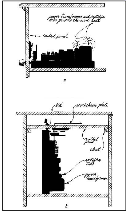
Fig. 101. There are two basic ways of mounting a tuner within a cabinet:
(a) tuner mounted horizontally; (b) tuner mounted vertically.
There are three types of tuners in common use: the FM, or frequency modulation type; AM or amplitude modulation, and AM FM, which combines the two in a single unit.
Most hi-fi units that include radio reception are equipped to cover the FM band, either in the form of a straight FM tuner or an AM-FM combination. Since FM reception is so far superior to AM, AM tuners as separate entities are relatively uncommon. Consequently, an AM tuner as an individual unit is most likely to show up on the AM side of a two-channel stereo receiver system.
In recent years, due to the widespread use of printed circuits, miniature tubes and miniaturized parts, the size of tuners has been considerably reduced over the early models. In the early days of hi-fi, it was not uncommon to find a tuner measuring 13 to 15 inches wide, 7 to 10 inches high and 10 to 12 inches deep. Any reduction in height or width of tuners simplifies cabinet installation since it reduces the amount of control panel space required by the unit. Considerable reductions, particularly in height, have been made in the physical size of tuners. Tuners are now made in such a way that heights of over 4½ inches are relatively uncommon. This has made it possible to stack tuners and amplifiers, resulting in extremely compact control panels.
Tuners tend to get warm in operation. This is normal and does no harm as long as adequate ventilation is supplied. In most cases, providing adequate ventilation for a tuner is not an elaborate procedure. Try to allow about l inch between the tuner and any other electronic part next to it in the same compartment or, if other parts are to be mounted over the tuner, try to allow approximately 3 inches. Preferably, leave the back of the cabinet compartment housing such parts open so that air can circulate in and out freely. It is also a good idea, where possible, to drill a series of holes, say 1 to 1 ½ inches in diameter in the shelf on which the tuner is mounted to allow air to circulate up from underneath.
Most manufacturers state that their tuners can be mounted either horizontally or vertically; that is, with the controls facing either front or up (Fig. 101). However, my experience indicates that horizontal mounting, where possible, is definitely preferable.
It seems to me that when I have mounted tuners vertically, they tended to burn out tubes a bit more rapidly. This apparent shortening of tube life is probably caused more by what the vertical mount does to the ventilation than by what it does to the tube orientation, since the vertical mount obviously requires that the tuner be brought up very close to the top panel, where there is very little space for air to circulate adequately. And, to make matters worse, generally the hottest parts such as the power transformer and rectifier are at the back of the chassis which in the vertical position becomes the bottom (Fig. 101-b). Their heat will therefore rise all the way up the chassis when it is placed vertically.
It makes no difference from the point of view of furniture installation whether the tuner is FM only or AM-FM except that the AM-FM tuner is generally somewhat larger than the FM only, has more tubes, generates more heat and therefore requires a bit better ventilation than the FM. It would seem to be so transparently obvious as to be unworthy of mention that a tuner and its associated control panel should be placed in the cabinet in such a fashion that the tuning dial can easily be read, but you'd be surprised how often this little consideration is ignored. Easy visibility of the dial is one of the major reasons advanced in favor of the vertical mount for a tuner. Personally, I feel the disadvantages outweigh the advantages in this case.
Record players
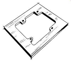
Fig. 102. For fixed installation of a record changer, a mounting board
is used. It can be obtained precut for various makes and models of changers
or can be made with templates supplied by the manufacturer.
Your second important signal source is the record playing device. It may be a record changer, a manual record player or a transcription-type turntable with a separate arm.
Unless you have
a large tape recorder, the record-playing mechanism is likely to be the largest single component in the entire system in terms of the cubic volume of space required for installation. It will therefore influence the overall dimensions of your cabinet more than any other single part. Although a number of manufacturers (both domestic and foreign) have record changers on the American market, the overall sizes are remarkably close. They will vary in height from about 7 ¾ inches overall to about 8½. In width they will range from 14½ to as much as 15 ½, and the largest variations will occur in depth, which may be from 13½ to 15½ inches.
---------------- 1 Do not confuse the transcription turntable and the manual record player. The turntable is a high-quality professional unit. The manual record player is considered by many to be more suitable than the changer, but it nevertheless cannot be classed with a true turntable.
---------------
Record changers can be installed in cabinets using a mounting board in which an irregularly shaped hole is cut (Fig. 102). The record changer is passed into this hole from above in such a fashion that the main plate, turntable, spindle and arm stand above the mounting level, while the motor and various levers and cams associated with the change mechanism hang down below (Fig. 103). Record changers are supplied with either three or four spring shock mounts through which they are bolted to the mounting board. Every model of record changer requires a different…
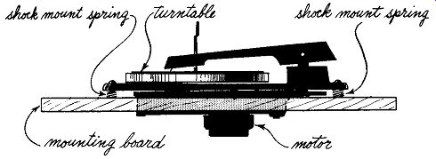
Fig. 103. Side view of a typical changer on a mounting board. Note the
spring shock mounts.
…shaped hole in the mounting board, but this constitutes no problem since every changer comes from the manufacturer accompanied by a template showing the shape of the hole required. The changer, on its mounting board, is installed in the cabinet by being set at an appropriate depth under a lid in a fixed position or attached to the top of a sliding drawer (Fig. 104). The clearances required above mounting level for record changers vary between 5¼ and 5¾ inches. I generally allow a flat 6 inches. The clearance required below varies from 2¼ to 2¾ inches. I generally allow a flat 3 inches, or a total of 9 overall.
Record changers, when not in use, must be kept covered by closing the lid or drawer, as the case may be. If they are left open, dust will accumulate on the turntable and be transferred from there to your records, causing unpleasant popping sounds as the record is played and also excessive wear on both the stylus and record.
When record players of any kind are installed in a fixed position under a lid, it is wise to allow a little extra space around the machine, if possible, so that it is easy to reach the controls, to place the stylus ~n playing position and to get records on and off the machine. In the case of a record changer placed in a drawer, be sure that you have a long enough traverse so that it will pull out far enough for convenient operation.
Beyond being sure that you've allowed enough space around the machine for convenient operation, a record changer requires no particular consideration in connection with cabinet installation. However, it must be fairly easy to remove for servicing.
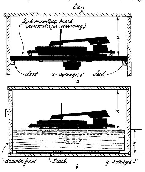
Fig. 104. Two ways in which a changer can be installed in a cabinet:
(a) mounted under lid; (b) mounted in drawer.
Turntables
The transcription turntable and arm will require more space in either length or width (or both) than a record changer or manual player. It will not usually require any more height. A turntable is a considerably more precise instrument, than a record changer in that it keeps more accurate speeds and it requires somewhat more careful installation.
Turntables are generally accompanied by a separate tone arm which holds the cartridge. This arm is often made by a manufacturer other than the one who made the turntable. It is essential in mounting an arm that the manufacturer's instructions as to the…
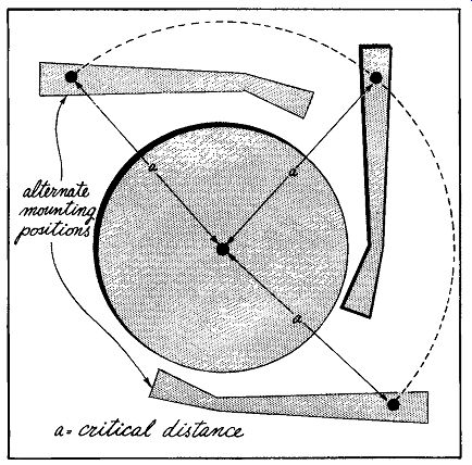
Fig. 105. When mounting a turntable and arm, the distance between the
pivot point of the arm to the center of the turntable is critical.
…distance required between the center of the spindle of the turntable and the pivot point of the arm be followed with extreme accuracy. ·where the arm is placed relative to the turntable is not usually important so long as the critical distance between the center of the spindle and the pivot point of the arm is observed (Fig. 105). Since most floors are not quite level, it is necessary to level the turntable mounting board after the cabinet has been put in its position in the room. This leveling becomes particularly important due to the fact that most turntable and arm assemblies utilize much lighter stylus pressure on the record than changers and, if the turntable is not level, the stylus and arm will not track accurately (Fig. 106).
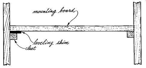
Fig. 106. When a cabinet is not level, the turntable can be adjusted
by inserting a shim between the mounting board and the cleat supporting
it.
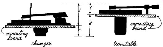
Fig. 107. Because pf their construction there is a difference in the
mounting level of changers and turntables: (a) room required for changer;
(b) depth needed for turntable. Note that the Overall depth is the same
for both.
While the overall height required for mounting a turntable and arm is no greater than that required for a changer, the heights above and below mounting level are different. Much less height is required above mounting level, and more below, than for the changer (Fig. 107). I generally average them out at 3 inches above and 6 below instead of the 3 below and 6 above that I use for the changer. The actual depth below mounting level required for a turntable may vary from 4 to 5¾ inches, and the height above from 2 to 2 ¾ inches.
When some low level magnetic cartridges are used (particularly stereo) annoying hum can be induced in the pickup by power transformers up to 18 inches away. Make sure that the turntable and amplifier (or any other equipment using a power transformer) are far enough away from each other to prevent hum pickup.
Occasionally a turntable with a particularly large motor may re quire a little more depth below mounting level than the average 6 inches, so it would do no harm for you to check the one that you have in mind to be sure that it will fit in the average space and, if not, allow the additional depth required.
The length and width requirements of a turntable and arm assembly are determined partly by the size of the turntable and by the length of the arm being used. Some of these arms have an over hang of 3 to 5 inches beyond the pivot point, so you have to be sure that you have sufficient space for this arm overhang to swing freely to allow the cartridge to traverse the entire playing area of the record (Fig. 108). A fairly good average space for turntable and arm assembly would be a surface about 18 x 22 inches. A large number of the various possible combinations will fit on this space; some will require less and a few odd ones will require more. The space requirements for these units are far more varied than for record changers, and you should check in each case to find out what your exact needs will be.
The one other remaining consideration in connection with turntables is that, since they have considerably larger motors than record changers, they require better ventilation. It is advisable to have either 2 or 3 inches of air space below the motor in the cabinet, or to open the back of the cabinet from the level of the mounting board down to allow air to enter and circulate around the motor. Some turntables have a small fan either inside or out side the motor, attached to the lower end of the drive shaft. If your motor happens to be one of this type, you can get away with a bit less space in the motor compartment. But, in general, too much space is far preferable to too little.
Tape decks and recorders
Quite a few tape mechanisms are available, both of domestic and foreign manufacture. Many are made for tape playback only, others with both record and playback functions. You may or may not have tape at the present; the chances are good that, in the fu ture, you will want it. It gives a kind of flexibility to your musical library that you can't get any other way and, of course, affords you an opportunity of recording miscellaneous material not commercially available that is of particular interest to you.
Unfortunately, however, tape machines are rather difficult to deal with in a general way as regards dimensions and cabinet mountings. They vary considerably in size, and they also differ in that some can be mounted vertically while others must be mounted horizontally. The size range runs from quite compact units that will fit in approximately the same space as a record changer, to the large, professional type units, some of which are pretty huge.
A good many tape recorders come in luggage cases, and a lot of people leave them in these cases with the idea in the back of their minds that they're going to carry the thing around a great deal to record material outside the home. It usually turns out that they don't but, by the time they find this out, they've already housed the rest of their equipment and their tape machine sits around the living room in its luggage case, becoming a bit of an eyesore.
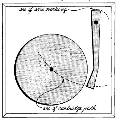
Fig. 108. Because the pivot point of the tone arm is several inches
from its end, allow room so that the arc of the overhang does not hit
the cabinet side before the cartridge arc can traverse the playing area
of a record.
One solution, if you really think you're going to carry your tape machine around very much, is to provide a space in your cabinet where you can put it, luggage case and all. If you decide to do this, the whole procedure is quite simple. All you'll have to do is measure the outside dimensions of the case and these will be the in side dimensions of the compartment you'll need. And you don’t have any installation problems except to leave holes in the compartment for leading wires to and from the rest of your system.
Many, but not all tape machines come in cases; a number are made specifically for mounting in furniture. The procedure for mounting is very similar to that for mounting a turntable. You have a mounting board set at the proper height. In most cases 2 or 3 inches above and 6 or 7 inches below mounting is plenty of room. You can cut a hole in the mounting board to the proper shape, as shown by the template supplied, drop your tape machine through the hole, and bolt or screw it in place. If you have a unit that is cased, but you are willing to admit at the outset that you really aren't going to carry it around, then the best thing to do is to take it out of the case and proceed in the same way as for an uncased unit. Your system as a whole is generally cleaner and better-looking this way, and it usually gets better ventilation.
When you start measuring the unit to find out how much space you need, don't make the mistake that is often made-of measuring it without the reels. Before you start, put on a pair of the largest reels that the machine will take, and measure your dimensions outside of those reels. Otherwise the reels will get in the way every time you try to dose the lid or drawer.
Most tape machines have a fan attached to the lower end of the drive shaft of the motor to provide air circulation. If your ma chine has more than one motor, this fan will be at the bottom of the main drive motor. If there is a panel of any kind close below the motor, try to cut a hole in the panel about the size of the fan.
This will greatly facilitate the cooling of the entire unit.
If you have a machine that mounts vertically, just leave the back off. In this way you will get excellent ventilation with no trouble at all. In general, plan to give a little more consideration to ventilation of a tape recorder than is necessary in the case of a turntable. The machine is more complicated and generally has electronic parts closely associated with the mechanical parts, thus generating more heat.
The last signal source that we will note is the audio end of your TV. Why many people insist on piping their TV sound into the hi-fi system is more than I can quite understand. Most of what you listen to on TV is speech, and it doesn't require a very high fidelity system to reproduce inte11igible speech. After all, the tele phone company reproduces an awful lot of intelligible speech through equipment with a frequency response range running from 100 to 3,000 cycles. On hi-fi, you're shooting for frequency response ranges of about 20-18,000 cycles. It seems to me that to use your hi-fi system for TV sound is a bit like shooting cannon balls at flies, but there are those who insist on doing it. If all you want to do is run your TV sound from the TV receiver, wherever it now is in the room, into your system, that, of course, does not involve any cabinet considerations. All you have to do is have an audio takeoff installed in the TV set, and run a cable over to your amp or preamp.
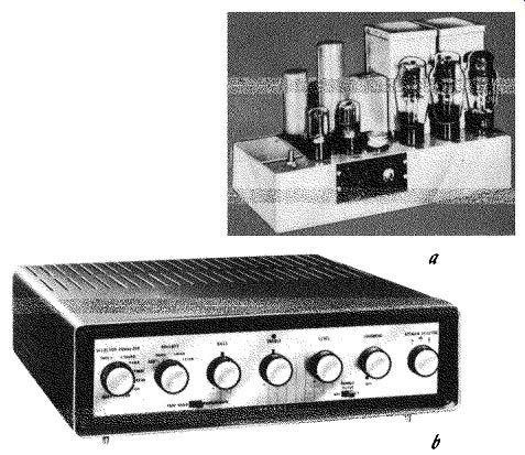
Fig. 109. Modem amplifiers of moderate power are much more compact
than their older brothers: (a) an old-style amplifier and preamp; (b)
the new flat look. (Lower photo courtesy Allied Radio.)
Where you run into cabinet considerations is when you have decided to put your TV in the same cabinet with your hi-fi system. Unless you have one of these new little portable jobs, your TV is probably a pretty large unit. It will considerably increase the over all dimensions of your cabinet not only in length, but very likely in depth. Often a system that normally requires a cabinet about 18 inches deep overall, suddenly becomes 24 inches deep when you add the TV. This is the point where you should stop and consider whether your room is big enough to take a cabinet of that size and depth. I have often seen rooms completely overpowered by the size of the cabinets that resulted from the incorporation of TV's with complete hi-fi systems. I cannot caution strongly enough against this way of doing things, except in very spacious rooms.
Amplifiers
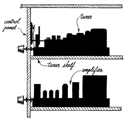
Fig. 110. Pancake type tuner and amplifier mounted horizontally in a
cabinet. Stacked mounting is one of the conveniences provided by flat
construction.
Your amplifier will generally consist of two main sections. The first is the preamplifier or control amplifier and the second is the power amplifier. Depending on size, power and type of construction, these two may be together in one unit or physically separated. Today, amplifiers of medium power (10-20 watts) are generally on one chassis while the larger, more powerful ones come in two parts or sometimes even in three (Fig. 109). Let's look at the smaller amplifiers first. In general, combination preamp-amplifiers are now being made in sizes and proportions roughly similar to those of tuners. They may be fairly wide and deep, but not very high. As with tuner construction, this type of amplifier represents a considerable departure from earlier models which had more height. This change in construction techniques tends to make both tuners and amplifiers much easier to mount in cabinets. In a slightly larger space than was formerly required by either a tuner or an amplifier, it is now possible to stack both of them, one on top of the other, making the entire equipment compartment modest in size and the control panel quite compact (Fig. 110). A large number of the smaller amplifiers can be easily accommodated on a control panel no more than 16½ inches wide by 12 inches high, with space to spare. Actually, very few of the flat amplifier chassis run more than 13½ inches wide, and a few of the smaller ones are as narrow as 9 or 10 inches in width. Heights range from 3½ to 4½ and in depths range from 9 to 12 inches.
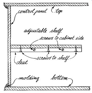
Fig. 111. Construction of a tune-amplifier compartment.
Where flat tuners and amplifiers are mounted one over the other in a compact compartment, it doesn't matter which one you put on the top. That is determined by your own taste. Installation of parts in such cases is very simple. Templates for the holes to be cut in the control panels arc supplied with each component. For whichever unit you have decided to put on the bottom, use the bottom of the compartment as the mounting level. Then, a couple of inches above that unit, so that there will be air around it, fix an internal shelf inside the compartment and behind the control panel. This gives you your mounting level for the upper unit. Cut the proper holes for both units in the control panel, as designated by the templates supplied. Place your components in position, plug them together and you're in business.
To mark the holes from the templates and make your cutouts.
first mark the level of the top of the internal shelf on the inside face of the control panel. Then take the control panel out of the cabinet. :Next, using the bottom and the shelf level as references, mark the cutouts from the templates and cut as required. In general, the control panels in cabinets designed to house high-fidelity equipment arc made removable so that this can be done.
If you design your own cabinet, be sure to include provision for making this panel removable. As far as that goes, while you're at it, make the mounting board for the record changer or the turn table removable also.
One simple way to arrange a removable control panel is to fix a frame of thin molding in the front of the compartment, then push the control panel in from behind, and screw it down to the frame from inside (Fig. 111 ). Be sure that you can get that internal shelf out, too. If the control panel is removable but the shelf is fixed, you'll obviously never get the control panel out.
This also is very easy to arrange. Merely fix the shelf to a pair of cleats, which in turn screw to the sides of the cabinet but are not glued. The whole business can then be easily removed and re placed by taking out a few screws.
Instruct your cabinetmaker specifically on these points, otherwise he will follow normal furniture-making procedure and fix these parts in place permanently when he assembles the cabinet.
There is still one other consideration. People have been known to buy hi-fi equipment and then find later that they want to change it. If you change your equipment, you can be absolutely sure that the new units will not fit into the old cutouts. You've got to take the old control panel out and replace it with another.
If your control panel is permanently fixed in place in the cabinet, instead of being removable, you'll have a rough time getting it out and you may well have to do considerable damage to the cabinet in the process.
In the case of the larger amplifiers consisting of a preamplifier and a separate power amplifier, the only part that has to come through the control panel is the preamp. These preamps are generally, if anything, smaller than the flat amplifiers discussed earlier. To install one, follow the same procedure as for the flat amplifier, except that you have a good deal less worry about ventilation of a preamp only, since it generates less heat than the combined preamp and amplifier. Once the preamp and tuner are taken care of, the only thing left to worry about is what to do with the possibly quite bulky power amplifier. Sometimes it will fit at the rear of the compartment in which you already have the other two parts. This is an excellent place for it, because it is likely to be the hottest unit you will have and, at the back of the compartment, it will be in a position to get the most air. If it hangs out the back an inch or so, that doesn't do any harm. In fact it does a little good as far as ventilation is concerned.
Don't push cabinets containing electronic equipment up tight against the wall. Set them out an inch or two so that air can readily get in and out of the compartments where the most heat is generated.
If your power amplifier is too big to fit in the same compartment with the other units, you will have to give it a separate compartment of its own somewhere else in the cabinet. But again, be sure that it is adequately ventilated. The more air it gets, the better. Leave the back off such a compartment and, if you find that you have to cut it down in size to where the amplifier is a very close fit, cut intake holes in the bottom of the compartment to improve air circulation.
Speaker enclosures At first glance, the subject of speaker enclosures seems like a gigantic and impenetrable wall comprised entirely of utter confusion. Acoustical engineers are in unanimous and happy agreement on one point and one only: to operate properly, a high-fidelity loudspeaker system must be enclosed or placed behind a baffle.
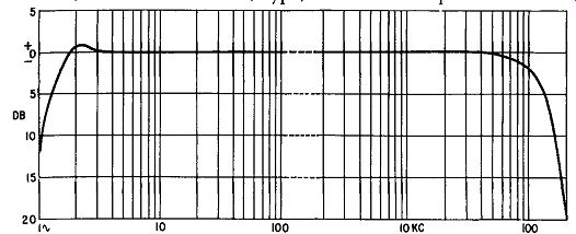
Fig. 112. Typical response curve for a high-quality amplifier. Note
the flat top.
From here on, the disagreements range from mild to positively vitriolic, as to what the size, type, form and composition should be. To avoid having my head chopped off at the ankles, I shall evade any evaluation of the various principles in current use. We will discuss types of cabinets utilizing different acoustical principles, but primarily from the point of view of the resulting external appearance.
Decide intelligently what kind of speaker cabinet you want, listen to a number of speakers in a number of different types of en closures and determine which one suits your ears the best. After all, your like or dislike of the various tonal qualities produced by different speakers enclosed in different ways is a highly personal matter. True, there is perfectly good sense, from the point of view of the engineers, in discussions of comparative specifications and frequency response curves. But, for the nontechnical person, this type of data provides, albeit precise, a fairly meaningless description of a result that either feels good or doesn't feel good to our ears. We each hear with a pair of ears that is a little bit different from the next fellow's.
You will hear a lot of talk about flatness of frequency response in the system, from some un-usably low frequency at the bottom to some other equally unusable high frequency at the top. If you're technically minded-or just plain curious-take a look at the response curve of a decent amplifier (Fig. 112). It will be pretty flat. But then take a look at the response curve of a pretty good speaker (Fig. 113). By comparison, it looks like the path of an alcoholic trying to get home from the corner saloon-it wobbles all over the place. What you may not know is that the frequency response of your ears is likely to be pretty wobbly, too. Now, if you happen to come across a speaker that dips in its response where your ears peak, and peaks where your ears dip, it's going to sound pretty flat to you-but it might sound pretty frightful to your next-door neighbor, whose hearing response is likely to be quite different from yours.
To complicate matters further, take the same speaker and house it in several different ways. You'll change its response each time you change the housing. On top of that, take the same speaker, in the same enclosure, and put it in three or four different rooms.
You'll change its response every time you change rooms.
Actually, if you want to delve into the technical aspects of speakers and their cabinets, there's a considerable amount of literature available on the subject in the form of books and articles. Also, there's a huge amount of material published by speaker manufacturers.
The infinite baffle
Now, as I have already said, engineers are agreed on one point--your speaker system should be in a housing. 'Without going into the whys, the reason for this is to improve the bass response of the speakers. There are a large number of different speaker enclosures and speaker systems on the market, but most of them will fall into one of three main categories:
1. Infinite baffle
2. Reflex baffle
3. Horn
Of these, the infinite baffle is probably the simplest and technically the most foolproof. In theory, an infinite baffle would consist of a plane surface of infinite height and infinite width with a speaker mounted through a hole in this surface. In such a situation the front radiation of the speaker would be completely isolated from the back radiation, and the air pressure or loading on the cone would be the same on both front and back. These conditions can be approximated by mounting the speaker through a hole in a wall between two rooms of roughly the same volume. In such a case the room that has the back of the speaker facing into it is, in its entirety, effectively a speaker enclosure.
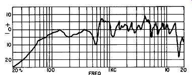
Fig. 113. Speaker response curves are quite different from those of
amplifiers. The hill-and-valley nature of a speaker's response is shown
in this typical curve.
This kind of thing has been done on occasion, but obviously it is. not a very practical approach. Therefore, the conventional infinite baffle, so called, is quite another thing. It consists simply of a box, fully enclosed on all sides, made as airtight as possible, with one hole in the front for the speaker. The only thing that's critical...
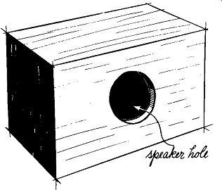
Fig.114. The conventional infinite baffle is primarily a big closed
box.
...about it is that it be large enough in cubic volume for the size speaker that you're using (Fig. 114). The relative proportions of height to width to depth seem to have very little effect as long as you somehow get the necessary cubic volume inside the enclosure.
But there's a rub. The infinite baffle, for a speaker of given diameter, is larger and more cumbersome than enclosures based on the other widely used principles.
--- There are other shortcomings inherent in infinite baffles. One of the most striking is the development of a single note bass resonance. When not properly designed the resultant bass-boom can be annoying. However, some ears find this juke-box-effect quite pleasant.
---------
The table shows the recommended cubic volumes of conventional infinite baffles for speakers of various diameters.
Speaker Volume
(inches) (cubic feet)
8 5½
10
6¾
12 8 15 10
Remember, these are recommended averages. Speakers vary quite considerably in response curves, range and cone resonance.
With some speakers, you can get away with a good deal less cubic volume than the recommended figure, particularly if it's a speaker with a very low cone resonance. In general, if you've got room enough to stick to the recommended sizes, do so. If you have space sufficient to allow you to exceed the volumes recommended, this is all to the good. If, on the other hand, you find you haven't got the space necessary for the recommended volume and have to pare it, be careful of what speaker you use. You could conceivably cheat the speaker. The speaker won't mind-but you might.
From the point of view of cabinet design, the infinite baffle, out side of its bulk, is a rather nice type of enclosure to work with be cause its relative proportions of height, width and depth are not critical3. Depending on the space you have available to allot to it, you can make it either long and low or narrow and high. You can put it on the wall, or you can put it in a corner. You can use a closet or you can build it into a skew-shaped space-as under a stairway-or some other odd-shaped niche for which you have no other use. It is entirely conceivable that, in your particular residence, you might have no place where you could put a speaker enclosure of even quite modest size if it has to be a regular parallelepiped shape, but yet you have a much larger area of irregular shape that could be used for the purpose. Some speaker manufacturers specifically recommend that their speakers be used in infinite baffles. In such a case, you would be wise to find some way of following the manufacturer's recommendations, since otherwise you will not get the sound from the speaker that the manufacturer intended and which was probably the sound that you heard demonstrated when you decided on it in the first place.
--------------
• The air-loaded enclosure, which can be considered a variety of the infinite baffle, is another matter entirely. This type of unit is designed for specific make and model speakers and its dimensions are critical. The enclosure and speaker are frequently sold as a unit. They are available in a utility finish for custom installation. The enclosure is quite small-2.5 cubic feet being a typical internal volume.
---------------
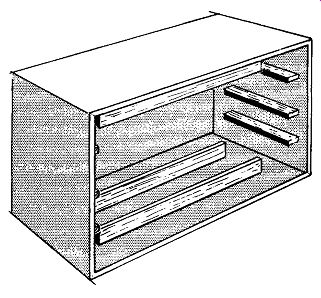
Fig. 115. The sides of a speaker enclosure are stiffened with battening
to prevent untoward resonance. They all strengthen the enclosure.
A few words of caution regarding infinite baffles are in order.
Because the infinite baffle is quite flexible as to shape and proportion, this sometimes leads people to put the speakers either too low or too high from the floor, particularly speakers that handle high frequencies. Low-frequency tones tend to disperse through the room reasonably readily, but high-frequency tones are directional, and dispersion becomes more and more difficult the higher the frequency. Wherever possible, try to get whatever speaker or speakers are handling the high end at about the same height off the floor as your ear will be when you are seated to listen. The overall result will be much more satisfactory. Due to the fact that conventional infinite baffles are pretty big boxes, the individual panels of which they are composed are pretty good sized. It is a good idea to stiffen them internally by adding battens, approximately ¾ x 1 ½ inches to 2 inches, edge-glued and screwed on the inside of the panels to aid in damping panel resonance (Fig. 115).
In the larger cabinets housing 15-inch systems or multiple 12 inch systems, it is often desirable to add cross-braces from top to bottom, side to side and front to back, made of stock as heavy as 2 x 4 inches, for the same purpose-damping panel resonances.
Lining the inside faces, top, bottom, sides and back of an infinite baffle with acoustical absorptive material such as 2-inch Fiberglas damps standing waves which will otherwise cause some quite annoying sound effects that have nothing to do with the program material you want to listen to.
Bass reflex enclosures
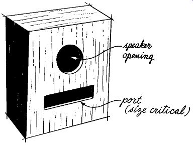
Fig. 116. The reflex baffle is a popular enclosure. The port actually
tunes the enclosure.
The next important type of speaker enclosure is known as a phase inverter or bass reflex. This type of unit is almost a sealed enclosure like the infinite baffle, except that it has an opening or port in the front, in addition to the speaker opening (Fig. 116). The purpose of this port is to utilize cabinet resonance along with speaker resonance, to extend the bass response downward and at the same time equalize it over a wider range. An advantage inherent in the phase-inverter or bass-reflex cabinet is that it allows you to use smaller dimensions for a speaker of given diameter than would be possible with an infinite baffle. A 12-inch speaker can be re-flexed in a cabinet as small as 4 cubic feet, and a 15-incher can be put in one as small as 6 or 6½ cubic feet.
In the case of the reflex baffle (as for the infinite baffle) some manufacturers specifically recommend that their speakers be used in this type of enclosure. Among the advantages claimed by those who advocate the reflex baffle are that it will damp the peak that occurs at the speaker's resonant frequency, at the same time extending the bass response of the speaker below the point that would be achieved with an infinite baffle. In addition, the speaker's efficiency is increased since the back wave is utilized as well as the front wave at low frequencies.
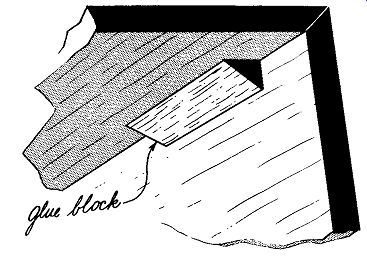
Fig. 117. Speaker enclosures have been known to come apart from vibration
and air pressure caused by a speaker working at high levels. Brace the
joints with glue blocks.
To get back to our primary concern, which is the external aspects of the cabinet, a reflex enclosure, like an infinite baffle, is quite flexible as to shape. It can be a regular parallelepiped, a corner cabinet or an irregular shape. If you use an irregular shape, you're sort of looking for trouble because you're liable to have an awful time computing the cubic volume to get the port size right. But, if you have no other choice, go ahead and do it that way but be very careful with your volume computations, or the whole thing is liable to come out sounding a bit off. Considering the necessity for accurate volume computations, the regular parallelepiped is by far the easiest shape to work with. However, it's not critical whether the shape is made long and low or high and narrow. And it doesn't make much difference whether the port is alongside the speaker hole or below, as long as the area is right and it is not too close to the speaker opening. So actually you do have a high degree of flexibility in working out the lines and pro portions of the reflex enclosure.
As with the infinite baffle, internal battering of the panels is a good idea. In this case, you're utilizing the cabinet resonance which you don't want mixed up with spurious panel resonances, if you can help it. In the reflex cabinet you don't use as much absorptive material as in the infinite baffle. Generally, absorptive material is applied to the inside of the back and then to either the top or the bottom and the right or the left side, but not both.
Both infinite and reflex baffles should be made of good, solid ¾-inch plywood, preferably with the joints reinforced internally with glue blocks (Fig. 117). Both baffle-boards and backs must be firmly screwed in place with screws spaced not more than 6 inches apart all the way around. Grille cloth should be as acoustically transparent as possible, otherwise you will attenuate the highs. The best materials for this purpose are woven of monofilament plastic yarn. Several companies specialize in the manufacture of cloths specifically for this purpose. Such cloth should be readily available from your components dealer. One rule-of-thumb test for the acoustical transparency of a piece of proposed cloth is to hold it up to the light in an otherwise darkened room and see how trans parent it is (Fig. 118). The reason for darkening the room is so that the color of the cloth will not affect your judgment.
Horns
The other type of cabinet of major importance, the horns, tend to get rather complicated. In fact, before even starting to describe them, I feel that I cannot caution you too strongly against at tempting to do the acoustical design of a horn yourself. This is not a job for an amateur. Even if you have enough acoustical engineering knowledge to design a horn, the chances are that you do not have the extensive and expensive instrumentation necessary to test what you're doing. If you want a horn and don't like the appearance of the ones you've seen, stick to the internal specifications of the one you like and change the outside appearance to suit yourself. If you take a cabinet of fixed dimensions, you can change its exterior appearance by varying external details. By adding, subtracting or changing moldings, legs, grille cloth, bases, etc., you can get immense flexibility in external appearance with out changing internal specifications one bit. But stop right there.
Don't try to change dimensions or proportions.
It is almost impossible to describe the design of horns in simple terms. The whole subject very soon becomes unwieldy. Horns can be classified in one way according to the type of curve upon which the flair of the horn is based. The curve most often used is an exponential one. However, another type of curve, the catenoid, has also been used fairly extensively.
A horn type speaker cabinet should not properly be called an enclosure, because a true horn operates as an extension and additional part of the speaker. Therefore, the speaker and its associated horn must be considered as a single integral unit. For this to happen the speaker must be specifically designed for the horn, or vice versa. Therefore, if you intend to use a horn type speaker system, be sure to use the right speaker in the horn you've picked or, alternately, the right horn for the speaker you have.
In addition to the three major types of speaker enclosures al ready mentioned, a number of other principles have been utilized for forming speaker enclosures. I shall not attempt to deal with them in any detail, but refer you to existing literature.
One device used strictly for reproducing basses and requiring separate arrangements for mid-range and treble is called an air coupler. These tend to be rather bulky and, from our point of view, rather limited as to the flexibility of proportion, making them a little difficult to design around.
You may very well come across types of enclosures not mentioned-it is impossible in a limited space to try to cover them all.
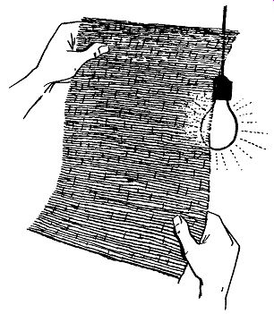
Fig. 118. The grille cloth must be acoustically transparent. One test
is to hold a piece up to a light. If you can see through it, chances
are that you can hear through it.
But no matter which you like and want to adopt, just be sure to check the possible effect of changes in size and proportion before you decide to make any such alterations. It is no great effort to inquire and a good deal better to do so than to suffer needlessly with unsatisfactory results.
• Do not confuse the air coupler with the air loaded low-efficiency enclosure. The latter units are small and extremely compact.
Stereo equipment considerations
Because there has been so much hoopla about stereo recently, no discussion of components in relation to furniture could be considered complete without mentioning the questions and problems stereo can raise.
Tuners
Although methods are being developed to broadcast stereo by FM multiplexing, as of this writing the only generally available stereo broadcasts are AM-FM; that is one channel is on AM, the other on FM. To receive and reproduce such broadcasts in stereo you need either an AM-FM tuner that can tune each band separately and has separate outputs for each band, or you'll need two entirely separate tuners, one for each band.
Stereo AM-FM tuners are available, and, while they are some times slightly larger than their non-stereo counterparts, if you have allowed adequate space for a monophonic AM-FM tuner, you won't have trouble getting a stereo unit to fit the same space.
Visibility of tuning dials may be more of a problem with stereo--you'll have two of them to tune instead of one-but, you ought to be able to see a tuning dial reasonably readily anyhow.
Ventilation is just as important to a stereo tuner as to any other. Stereo equipment won't run any cooler; on the other hand, it will not run much hotter either. Venting adequate for a straight AM-FM tuner is not likely to stifle a stereo unit.
If, for any reason, you are committed to keeping a non-stereo tuner, but still want stereo, then you may have a bit of trouble.
You have to get another tuner, and the second one must be treated with just as much courtesy and consideration as the first.
Record changers
Here we find a very happy situation. There is no difference at all in the physical size of a record changer, be it mono or stereo.
Be a bit more careful about the mechanics of mounting the changer, however. If the shock mounts are very springy, as they often are, put in a bit of steel wool to damp them. Be rather more careful to level the changer when it is to be used for stereo.
Remember, in stereo you are getting information from both sides of the record groove so you don't want to start off with the stylus tending to lean more toward one side than the other.
Turntable and arm Here again, from the point of view of the space required for housing in furniture, there is no difference between a mono phonic table and arm and a stereo unit. When playing stereo records, the stylus pressure must be as well centered as possible in the record groove. All considerations previously discussed relating to turntables and arms still hold true.
Tape machines
The extent to which stereo will affect the housing of your tape machine depends largely on the type of machine. This does not mean the make, but rather what it is intended to do. Some tape machines are set up to record monophonically only, but will play back either mono or stereo. Others will perform both recording and playback functions in either mono or stereo.
The units that play stereo but will record only mono differ in physical size very little, if at all, from their strictly monophonic equivalents. They, therefore, introduce no problems. However, the machine that will both record and play back stereo will, of necessity, be somewhat bulkier than its simpler mono brother.
This is primarily because of the unavoidable addition of a second complete record preamp. In machines designed so that the electronic parts are mounted in one integral unit with the mechanical parts (the tape transport), the additional space may be taken in any direction, length, width, depth or any combination of these. As a result, the only solution is to measure the make you want to use, and revise as necessary the space you have allotted to tape in your cabinet plans.
If, however, your tape equipment is designed with the electronic parts completely separate from the tape transport, the transport space will be unaffected by a stereo conversion. But the preamp space will be nearly doubled, because now you must have two of them.
Preamps and Amplifiers
For stereo, as for mono, amplifiers arc sometimes designed with the preamplifiers on the same chassis, and other times separately. High-powered amplifiers will generally be separate from the preamps while the ones boasting, say, 10 to 20 watts per channel, are likely to combine both functions on one chassis.
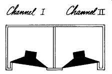
Fig. 119. The simplest stereo setup, but the least desirable acoustically,
is to have both speaker systems in a compartmented enclosure.
This is actually quite a trick, if you will just stop to think about it. Two independent amplifiers plus two independent pre amps have been piled on a single chassis, and in the process they have been kept down to remarkably manageable size. The average stereo combination preamplifier-amplifier delivering up to 20 watts per channel will measure 15 to 16 inches wide, 4½ to 5 inches high and 10 to 12 inches deep. This is very compact considering what is included in the package! Yes, it's bigger than a monophonic amplifier of comparable power per channel, but it is nowhere near twice as big.
The preamp will approximate the size of the complete amp preamps we've been discussing. You may be able to pare an inch or two from the width or the depth, but the height won't come down much. The main difference in size between the mono and the stereo preamp will usually show up in the depth.
Speakers
Actually you have four alternatives to choose from in setting up stereo speakers. The first, and least desirable for reasons that will be dealt with in the next section, is to mount two separate speaker systems at either end of a single enclosure that is partitioned down the middle to divide it into two entirely separate compartments (Fig. 119). By least desirable is meant least desirable acoustically. From the furniture point of view, this is by far the simplest method.
The second method is to use two identical speaker systems in two identical enclosures (Fig. 120). This method is generally the best because the speakers can be placed at whatever distance and angle from each other that is best. The obvious disadvantage is that, first, you've got to have a second box, and also you must find space somewhere for it.
The third method is a good compromise when there just isn't space to put two complete speaker systems in the room.
For one channel set up a complete speaker system as you would for mono, but cut the woofer off at 250 to 350 cycles, the lower the better. Don't let it get up into the mid-range. Use a separate speaker or speakers for mid-range and high-frequency speakers of this system only and put them in a small box for the second channel (Fig. 121). Since the stereo effect is achieved primarily in the mid- and high-ranges, and since the speaker systems are separated in these ranges, things will work out well.
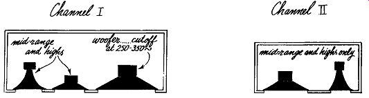
Fig. 121. Stereo setup using different speaker systems.
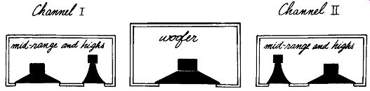
Fig. 122. Putting the woofer in the center gets rid of the apparent
dead spot in the middle.
If you like cabinets and in addition have a huge room, the fourth alternative is for you. Put your woofer in one cabinet in the middle and set up two mid-range and high-frequency systems in two separate cabinets spaced out on either side (Fig. 122).