In almost every discussion of tubes and their peculiarities, the subject of tube testers is bound to be raised sooner or later. Indeed, there is probably no more universally misused or misunderstood piece of equipment in the field today than the modern tube tester. In order to try to dispel some of the mystery, or what at times amounts to downright superstition, with regard to these devices, much of this section will be devoted to an explanation of their basic characteristics and capabilities.
One of the principal reasons for the wide divergence of opinion regarding the merits of tube testers stems from the many individual motives behind tube testing. There are at least three, and perhaps four, distinctly different motivations behind those who want to test tubes. Tube tester manufacturers are fully aware of this, and they design their many models in an attempt to satisfy these various aims. When used for the express purpose for which they were designed, most of these instruments perform useful and necessary functions. It is certainly not the fault of the manufacturers that many users of their instruments fail to understand their real purposes or limitations.
EARLY TUBE TESTERS
The original purpose of tube testers was to provide tube sellers with a means for making on-the-spot proof of tube operability. Since tubes have been sold to all sorts of do it-yourselfers right from the earliest days of radio, they were sold on a no-exchange basis, and it was necessary to show the customer that the tube was working when he purchased it. For this purpose, early tube cartons were made in such a manner that the prongs could be inserted into a tester socket without removing the tube from its factory-fresh carton. Proving that a tube was good merely meant that it had an intact filament and that it was cap able of emission.
For this type of service, the instrument had to be extremely simple. It was often used by salesgirls or other nontechnical people, and all they wanted was a "good-bad" indication. Such checkers tested all tubes as diodes. About the only adjustments were the filament voltage selector and the meter shunt, or "English" dial. This same type of instrument, with very few modifications, is still being used today in some of the so-called "quick checkers" and drugstore do-it-yourself checkers. There are even some portable models which can be carried into the home to perform this same "good-bad" test where the customer can see it being done.
As the business of servicing electronic equipment be came larger, the need for a better instrument that could help the technician in diagnosing defective units became apparent. Such an instrument needed greater flexibility than the simple device just described. It needed individual connections made to the different tube elements, as well as some sort of a qualitative measure of the tube's performance. This gave rise to the multiswitch units that measured something called "dynamic mutual conductance." These instruments are present today in large numbers, and constitute the largest single type of tester used in the industry. They are not as fast as the simplest type, but they are not as crude either, so what is lost in speed is made up for in the relatively greater meaning of the information they provide.
A third fundamental need for tube testing is found in the more advanced service and maintenance establishments, and in schools, laboratories, and factories, where the emphasis is more on measuring tube defects and in making a more significant quality comparison. Instruments for such usage have to be somewhat more flexible than either of the other two types. They must apply individual voltages to each element in the tube, and usually allow for individual adjustment of these voltages, or at least some of them. They will also provide a measurement which is closely correlated with true transconductance.
Finally, we have the need of the laboratory or the large user of tubes who wishes to measure tubes in terms that are standard throughout the industry. For this purpose, the tube tester must be extremely flexible. It is necessary that each electrode in any tube be separately supplied and separately monitored, both for voltage as well as for current. It is necessary that the driving voltage be adjustable and monitored. The output indicator must be independent of the DC current flowing in the plate circuit, and it must read in terms that are standard and repeatable from one instrument to the next.
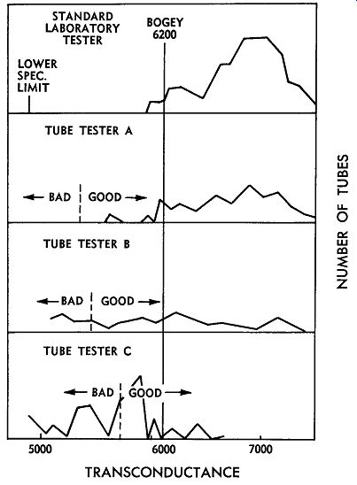
Fig. 8-1. Comparison of results obtained when a number of tubes were tested
in three commercial tube testers and in a standard laboratory tester.
From the foregoing, it should be apparent that the various needs for the different kind of tube checkers precludes any possibility of there being a universal instrument. No one instrument can fulfill all these requirements. The simple fast-check device is not capable of measuring tube characteristics with any degree of accuracy, other than to indicate those that are "dead." On the other hand, the complex tube tester which is capable of measuring qualitatively, requires special skill and knowledge on the part of the operator. Furthermore, operation and evaluation is necessarily too slow and much too elaborate for it to be used as a portable instrument. So we come to the inevitable conclusion that a tube tester, in order to be practical, has to be designed with some compromises. It is thus questionable as to whether or not these devices are capable of providing all the information needed to predict the probable usefulness of tubes used in a given piece of apparatus.
Evidence of this is given in Fig. 8-1, which shows the result of testing 100 tubes in three different commercial tube checkers and comparing the results with those obtained from testing the same tubes in standard laboratory equipment. It will be seen that instrument "A" shows reasonably good correlation. This is an instrument which applies appropriate voltages to each element of the tube under test. It is a top-quality service-type instrument.
The instrument designated as tester "B" is a somewhat simpler unit. It uses a metering circuit wherein the DC plate current of the tube under test plays an important part in the actual reading. This is shown in the much wider spread of its readings. Note that although 95 percent of all the tubes were actually over the bogey or published value for transconductance, this tester read over half of them as being below this value.
The final instrument is of the quick-test variety which connects all tubes as if they were triodes. The lack of correlation here is all too apparent, inasmuch as the readings are completely unrelated to transconductance. Not only did most of the tubes "fail" on this tester, but some of them, when retested in the laboratory instrument, had lost much of their transconductance. This was found to have been the result of the excessive current drawn by the quick-tester. Tubes are operated as triodes in this tester, and raw AC voltage is applied to all elements, including the grid. In relatively high transconductance tubes, the grid is very close to the cathode. Heavy rectification current, caused by driving the grid positive, results in excessive heating of the grid wires. This causes the grid rods to warp and critical spacings to become upset, ac counting for the loss of transconductance discovered during the comparative reading tests.
CLASSIFICATION OF TUBE TESTERS
We have been discussing the general classes of tube testers in a somewhat remote manner. Actually, this isn't necessary because there are EIA standards which define the various classifications of tube testers very completely.
This allows the individual purchasing one of these devices to know just what he is getting for his money. Although the availability of these standards has not been widely publicized, they can be obtained by anyone who is interested enough to write to the manufacturer of the instrument in question, asking him in what classification his instrument falls.

Fig. 8-2. Four basic circuits used in tube testers, as specified by EIA standards.
The EIA standards for tube testers recognize only four basic circuits. Fig. 8-2 shows these in their simplest form, and are identified as Groups I, II, III, and IV. It should be explained that various mechanical and electrical features will distinguish one model from others in the same group. Such variations as push buttons, punched cards or prewired panels do not in any way change the ultimate effectiveness of the instrument. They can only affect its convenience. Likewise, no distinction is made regarding the tolerances or the accuracy of the various instruments in a given group. Such things as filament voltage regulation are important quality considerations the user should explore before investing his money. For example, he should try inserting a tube with a heavy heater current in the tester and then reading the actual applied filament voltage. Does 6.3 volts turn out to be 4.7 volts? Would you check a new car, or a used one for that matter, with kerosene in the gas tank? Then why try to test a tube at any voltage other than the one at which it was designed to work? Let's examine the four basic types of tube tester circuits and see just exactly what they are and what they can and cannot be expected to do. Tube testers in Group I are defined as "a device incorporating a circuit in which all available electrodes except cathode are connected together and an AC voltage is applied through a DC indicator between the interconnected electrodes and cathode." This is a common emission checker or "dynamic emission" checker where the tube is used as a rectifier to provide its own DC current. Such testers usually apply the same potential to all tubes, merely changing the value of the meter shunt to keep it from going off scale on the higher conductance types. Usually, no consideration is given to the fact that true emission testing should be performed at a different voltage for each tube type. Placing just any voltage across a tube, and drawing all the emission current the cathode will supply, is a sure way to gas up many tubes and to warp grids or cathodes in others.
Tube engineers know that every cathode has a maximum safe current limit. This is based on the area of the cathode, and a specific constant applies for any given type of cathode construction. This constant is expressed in terms of the current per square centimeter of cathode area. If this limit is exceeded, damage to the cathode surface will certainly follow. It may not be immediately apparent; in fact, it probably won't be. But it will shorten tube life just as sure as racing a cold motor will shorten its life.
Group II tube checkers are defined as "a device incorporating a circuit in which separate AC voltages are applied between grid and cathode and between other elements, individually or collectively, and cathode. A DC indicator is connected in series with the plate." Such devices make a simple AC amplification test, which is only vaguely related to true transconductance.
Because these instruments use a DC indicator in the plate circuit, they are heavily influenced by the actual DC plate current of the tube under test. In other words, two tubes having similar trans-conductances but different plate currents will differ widely in their readings. This would be of small concern were it not for the fact that the tube having the higher plate current will read as the better quality tube. It will read higher on the "good-bad" scale, or on the transconductance scale, if one is provided. Two things may happen in this case. First, if the tube is used in a circuit where the effective plate load is high, it will not be able to draw the higher plate current; so in reality, its transconductance will be lower than actually measured during the test. Its performance, as actually measured in the equipment, will thus be inferior to the tube which gave a lower "good" reading on the meter. Second, if the tube is used in a circuit where the load resistance is low enough to permit the higher plate current to flow, it will run hotter than the second tube and thus will not last as long.
This is an example of the weakness of this type of tester to check tube "quality." Actually, it is possible for the tester to pick the wrong tube as being the "best" one, either from the standpoint of initial performance or of useful life. It is the one most common situation encountered when using an instrument in which plate current, and not signal current, is used in obtaining a measurement.
Another point to consider regarding instruments in Group II has to do with their method of applying a grid signal. A common signal is usually applied to all tubes regardless of their normal bias requirements, sharpness of cutoff, or anything else. This results in many tubes being overdriven into their positive grid regions. When this happens, the grids conduct, thereby loading down the signal source and effectively reducing the amplitude of the drive. This results in lowered plate current and a lower reading on the meter, which tends to place a premium on remote cutoff tubes. Tubes having poorly aligned grids can actually rate much better in this type of tester than those that are mechanically perfect. Since misaligned grids may also contribute to lowered transconductance, these are really the poorer quality tubes; yet, they may read best on such a tube checker.
These are two examples of why most tube engineers will agree that you can't measure tube quality with a checker classified under Group II standards. Yet, there is probably the opinion among most users of tube testers that tube engineers frown on them because they call too many of his "good" tubes "bad." This may be true, but it is just as true that no instrument can err on one side of the ledger all of the time. These devices are often indiscriminate. They are, on occasion, capable of calling "bad" tubes "good"! Group III tube checkers are defined as "a device incorporating a circuit wherein separate grid signal and bias voltages are applied with the indicator responsive only to the grid-signal-produced component of the output current." Here at last we are beginning to deal with a measuring device. Instruments in this class provide individual bias and signal sources so that the tube can be operated in a manner similar to that in which it will be used. Grids are not driven into conduction, and the indicator is not dominated by the DC plate current. Such an instrument may be said to read transconductance, or something very close to it. Because of practical considerations, the signal voltage amplitude may not be exactly known and the output indicator does not have zero impedance, as it should have, but these are very minor deviations from the ideal.
Provided reasonably good voltage regulation is built into the instrument, it is capable of making comparative checks on tubes, using transconductance as the measure of quality.
The only argument that can be brought up in connection with such an instrument is the fundamental one regarding the significance of transconductance itself. Where the application is one which involves Class A amplification of a sine wave signal, there can be no question but what trans conductance is a good figure of merit. There are limitations to its use as a direct indication of individual tube merit, as pointed out in the previous discussion of correlation. But having granted its general usefulness as a measure of the gain characteristics of a tube, we then have to ask the logical question, "In how many typical applications are tubes used as Class-A amplifiers of sinusoidal signals?" The answer is something less than 10 percent, which means that even the finest instrument avail able for reading transconductance is reading a characteristic which can be correlated with only about one out of every ten applications.
What of all the other applications where some other characteristic, such as zero-bias plate current, pulse emission, cutoff, or power output are most significant? Can transconductance be used in any way to indicate whether or not a tube has these other essential characteristics? Only in one very limited sense. If a tube is dead and has no transconductance, it will have none of these other characteristics either. That we can say with certainty-but the opposite is not true. Because a tube has normal, or greater or less than normal, transconductance can in no way be interpreted as an indication of how it will perform in a pulse-operated circuit. Therefore, we must conclude that a tube tester, no matter how accurate it may be, can give us information which is only of very limited value in estimating just how well a tube will perform in its ultimate application.
Group IV testers will not be discussed except to point out that these are the laboratory type instruments used by tube manufacturers and others interested in making standard measurements in a standard manner. Their ac curacies are unquestioned and are usually periodically calibrated against the National Bureau of Standards.
Nevertheless, they will not perform any miracles. They can only read tube characteristics, such as transconductance, plate resistance, or amplification factor. They can make no valid predictions about tube performance in many kinds of applications. For these purposes, special tests are added to these instruments, including pulse generators, scopes, and various forms of high frequency reactance measuring apparatus. In spite of all this, it is almost impossible to estimate a tube's performance from readings alone. It must eventually be tested in the equipment for which it is designed.
SHORTS AND GAS TESTS
What about the use of tube testers in estimating the amount of degradation a tube has suffered in service? Can they be used to tell when a tube should be replaced? This involves the other circuits often found in a tube tester, intended to show whether the tube is shorted or gassy. The problem here is one of degree, and is less easily answered than the one involving transconductance. Trans conductance is a well-defined, mathematically-expressible voltage and current relationship which can be reproduced anywhere, anytime, by anyone. But what is a short circuit? You undoubtedly thought you knew until you tried to define it in terms of resistance. What will we call it? Is it a circuit having zero ohms, 10 ohms, 100 ohms, or 10,000,000 ohms? There are short-test circuits in some tube checkers that read "short" when the resistance between two terminals is 10 megohms. This is not a short circuit! This is very high resistance leakage and, consequently, it is extremely doubtful that it will have any effect on most normal circuits. A tester which utilizes a meter to indicate the true value of the short is much more helpful, since readings can be compared with engineering specifications.
All tubes have some leakage between elements, even when they are new, and this leakage increases with life.
But it usually has to fall far below a megohm before it has any significance. The point is that these leakages are not something that you can set arbitrary limits on. Take, for example, the very real case of heater-to-cathode leakage. Heaters are insulated from themselves and from the cathode sleeve into which they fit by a coating of aluminum oxide. This insulation must operate at something like 800°C, and still offer millions of ohms of resistance to the flow of current. This resistance naturally decreases as the amount of area increases (a simple application of Ohm's law-the more parallel resistance paths you have, the lower will be the net resistance between the two points which the paths connect). In low-powered tubes, the cathode and heater areas are small. Thus, the amount of surface exposed to leakage is also small. But high-powered tubes must have larger cathodes and more heater folds, so there is more area exposed to leakage. Logically, therefore, heater-to-cathode leakage in the high-powered tubes should be greater than in the smaller, low-powered types. This is shown in Fig. 8-3, which is a chart of heater power versus the normal leakage of a number of well-known tube types. The range is from a minimum of five microamperes to a maximum of 100 microamperes. How can there be a single test for leakage for all of these tubes? If you set the limit at 100 microamperes, you will pass a lot of tubes that should be rejected. If you set it at some point less than 100 micro amperes, you will reject many good tubes as "shorted." Aside from the foregoing ambiguities, there is the possibility of short tests causing tube damage. The manner in which these circuits generally work necessitates the use of a rather high voltage. This high potential, in being applied across the tube elements under test conditions, can produce "shorts" where none previously existed. It may do this by electrostatically attracting particles of cathode coating, causing microscopic bridges from grid to cathode, or causing the fusing together of microscopic particles of metal on the mica insulators to form solid connecting paths between other elements. However it is accomplished, repeated "short" testing of otherwise good tubes in a typical tube tester may result in some of the tubes reading "short" after sufficient tests have been performed.
Let's take a look at the so-called "gas" test circuits in some of these testers. We say "so-called" because, except in rare instances, they do not measure gas. They measure a grid current, but the question is which one and how much? These tests are based on the assumption that any grid current is a sign of a bad tube. This, of course, is not true; some circuits depend on one of the several possible grid currents in order to function properly. Eliminating all tubes that show any signs of grid current conduction without regard to which one or how much is like throwing the baby out with the bath water.

Fig. 8-3. A chart of heater power versus the normal leakage of a number of
well-known tube types.
So what have we learned? Except in the small percentage of cases where transconductance can be used as an indicator, tube testers do not measure anything that can be truly related to tube quality. And it is quite obvious that no tester can predict how well tubes will perform in a given circuit-not even the $10,000 instruments used by tube manufacturers! It takes a tube engineer with many years of experience to interpret information provided by such instruments.
What good, then, are tube testers which are more modestly priced? Well, even the crudest test will provide certain indications of discontinuity or abnormality. For example, if 20 tubes of a given type were dropped into a bucket of water, and only one of them sunk while the others floated, it is reasonable to assume that the one that sunk is bad. This does not necessarily mean, however, that the other 19 tubes are good! They have passed only this one test, and it is conceivable that other tests would eliminate a few more tubes which would not conform to a pattern set by the others. Of course, if only 10 tubes float while the other 10 sink, the test has no validity whatsoever-except to prove that a specific type of tube may, or may not, float.
Obviously, the above is grossly exaggerated, but similar reasoning can be applied to tube testers. On the basis of one or more tests, a suspected tube either conforms to a predetermined norm or it doesn't. The greater the number of significant tests made, the greater are the chances of proving a tube good or bad.
Tube testers, therefore, are particularly helpful in pro viding indications of abnormality. Direct substitution for a suspected tube is the best test of all, but even this is still not entirely conclusive. Not having a replacement tube at hand, use of a tube tester can provide indications as to whether or not a tube could be causing the trouble.
At least, if the tester shows a tube to be good, tests of other circuit components are in order; if the tester shows it to be bad, a replacement should be obtained and tried before spending time on other component tests.
Thus, the value of a tube tester really depends upon the user. It is up to him to know what is being measured and how to interpret the results. Further, by remembering that the indications of tube testers are not always conclusive, he will use his instrument judiciously-either to supplement other tests or confirm suspicions, or to provide indications that will guide him in making further tests.
MAINTENANCE PRACTICES
Electronic maintenance is a big job today in many phases of our industrial society. There are installations where thousands of tubes are involved and where the annual bill for maintenance and replacement is very substantial. There are competent engineers and technical people involved in the problem of keeping this equipment running with a minimum of expense-and even more important, with a minimum amount of "down" time. Such individuals have often asked for information on the various methods used in formal maintenance programs, their relative merits, and, if possible, for the one best method of obtaining the maximum benefit from men as well as equipment. The closing paragraphs of this section will attempt to answer these inquiries.
One of the oldest methods of performing routine maintenance of electronic equipment has been to set up a pro gram of planned replacement. Under this plan, tubes are removed after some arbitrary period of time, regardless of their condition, and replaced with new ones. This system has one very serious drawback; it completely ignores the laws governing failure patterns. The most unreliable period in a tube's life is the first one hundred hours of usage. (Fig. 1-1 in Section I illustrates this classic truth.) Therefore, by completely re-tubing the apparatus at regular intervals, the period of unreliability is perpetuated, and unpredictable failures will be more sudden and more numerous than would normally be expected.
Arbitrary wholesale replacement is therefore not recommended except in very rare instances dealing with certain known short life tubes. Even in such instances, there are better methods, which will be described a little later.
Another favorite maintenance procedure is to periodically remove all tubes for test and replace those found to have some measurable defect. This practice is undesirable from an extended tube life point of view. In the first place, it involves handling a lot of tubes, which means that some will inevitably become damaged through pin breakage, glass strains due to hasty insertions, and by being dropped or bumped. Some of these damages will go unnoticed, and the tubes will be put back into service, only to give trouble later. Then there are the facts established earlier; namely, that certain tube checkers don't provide indications which correlate with end usage, and that certain tests themselves may make a defective tube out of one that was satisfactory-or they may only make it a potential failure. So this procedure is not recommended either, first of all because it is costly, and secondly because it gives little assurance of reliability.
A third method, which may be regarded as almost no method at all, is to wait until something stops functioning before ferreting out and replacing the defective tube.
While this system has the advantage of simplicity and the assurance of maximum usage of the tubes, it lacks any element of prevention. Therefore, it cannot be recommended except in cases where duplicate standby equipment is always available. When this is the case, it may be the most efficient method of operation.
A minor modification of the above method, one which offers a more reasonable degree of preventive maintenance, involves periodic testing of the entire apparatus for some functional characteristic. If some over-all response-such as power output, gain, or signal-to-noise ratio-can be measured without disturbing any functioning part, evidence of deterioration can usually be spotted and an analysis of its cause begun before a major failure takes place.
If the entire unit cannot be so tested, then perhaps sections of it can. When performing this kind of a test, it is very helpful if the line voltage can be dropped a measured amount and the change in the significant characteristic noted. Among the useful techniques for sectional testing of much apparatus is the square wave or pulse technique.
A pulse of short duty cycle will often disclose information which can be correlated with specific elements within a given piece of equipment.
In a highly sophisticated maintenance program, it will be found advisable to have some system for double checking of all tube failures. This should be done by some individual other than the one who rejected them in the first place. A very large percentage of tubes that fail in one specific application may be perfectly satisfactory in some other application. Sometimes they will be found to operate quite satisfactorily in their original application, having been rejected in error.
It is advisable to have some method of marking such "reissued" tubes so that when they are rejected a second time, they can be disposed of forthwith. While at first it may appear to be taking an unwarranted risk to reuse a tube which has been previously rejected, experience has shown that, with a little judgment, such a program can usually cut annual tube replacement costs by as much as 30 percent without increasing down time a bit. It should be pointed out, however, that the use of reissued tubes is recommended only where accurate and detailed records can be kept; thus, the practice lends itself more readily to equipment used in industrial and military applications than for home entertainment units such as radio and tele vision receivers.
Finally, there is the matter of keeping adequate records--again, particularly with regard to industrial and military equipment. This is perhaps the most important part of a good preventive maintenance program. A record should be maintained of every tube replacement. Every socket in every piece of apparatus should have a record card. Each time a piece of equipment is serviced, a record should be made of the tube type, socket number, supplier's name, and the technician doing the work. Although maintaining this record may appear laborious and unnecessary, it will pay for itself many times if kept up to date.
Studies prove that most failures are predictable and preventable, if you have adequate records to show you the trends. Some circuits will prove to be much tougher on certain tubes than others. Learning why may prevent further failures. Some tube types may prove quite unreliable when compared to others. Designing these out of the equipment, or changing their operating conditions, may reduce their failure rate. Some supplier's types may not be as reliable as others. Records will prove this, and permit you to make a better choice of supplier. Studies based on good records will almost always show methods of reducing failure problems and obtaining better combined equipment and tube life. Like accidents--most tube failures don't just happen, they are caused--and records can point to the causes.