ONE of the most important things to learn about measurements in general is the distinction between absolute and comparative criteria. In audio, for some measurements it is important to obtain a degree of precision in absolute terms. For example, sup pose you want to know how much power output an amplifier produces. The formula for power output is volts times amperes equals watts. If an instrument is used with a series of markings across the scale which are not calibrated accurately in electrical units, any calculation of power must be indefinite.
If a voltmeter reads 10 volts, when the actual voltage is 9.5, and the ammeter reads 5 amperes when the current is really only 4.7, the calculated power is 10 x 5 = 50 watts while the actual power is only 9.5 x 4.7 = 44.65 watts.
For this reason it is important to know the exact voltage and current delivered by the amplifier. However, when measuring other aspects of the performance of an amplifier, precision of this kind is not needed. An example of this is frequency response, which is an expression of the relative output level at various frequencies.
Instrument limitations
If an input of 0.5 volt produces an output of 10 volts and the circuit is arranged so that the same meter is used for both measurements, then it is relatively unimportant (when determining frequency response) whether the input is exactly 0.5 volt. If it is 0.4 volt, then the output will be 8 volts, but the ratio between the two measurements remains at 20 to 1.
[...] readings when connected to the odd-shaped waveform at the out put because of the different kinds of rectification used.
The difference in readings can sometimes be observed before it is realized that the output is distorted. This difference supplies the clue that the waveforms of the amplifier should be examined. Obviously what is being measured must be seen to determine whether the waveform is the sine wave it is thought to be.

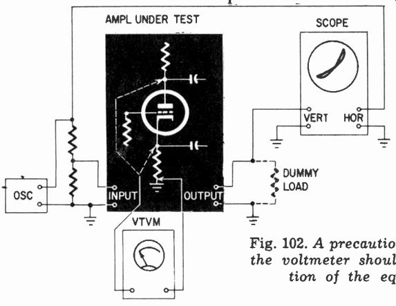
Fig. 102. A precautionary measure. Connecting the voltmeter should not disturb
the operation of the equipment under test.
Loading
Sometimes the ac voltage measured at the cathode of a split-load phase inverter (or the grid of the tube it feeds, as the case may be) will appear to be much more than that measured at the plate (or the grid of the following tube). From this measurement it can be erroneously concluded that the phase inverter is faulty in some way. In point of fact, the difference in reading is due to the different loading effect of the voltmeter on the two circuits.
But you can't measure the voltage at these points without applying the voltmeter or some other measuring instrument. How is one to know whether the connection affects the voltage reading? In this example, a simple method of checking is to put a scope or voltmeter (or both) across the output of the amplifier. If connection of the voltmeter to any test point affects the reading, it will also affect the signal from that point on throughout the amplifier. The technique, then, is to connect a scope to the output terminals of the amplifier with the voltmeter applied alternately to the plate and cathode of the phase inverter (Fig. 102). Watch what happens on the scope. Probably the scope will remain steady when the voltmeter is connected to the cathode, but a considerable change in waveform will occur when it is applied, to the plate.
Spurious effects
Loading, however, is not the only way in which the measuring instrument can invalidate the measurement. The capacitance of the connecting leads can produce enough extra capacitive coupling from one point in the amplifier to another to make it become unstable. This again means that the reading on the voltmeter is completely misleading.

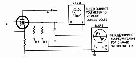
Fig. 103. Using a voltmeter to check that connecting a scope does not disturb
the circuit.

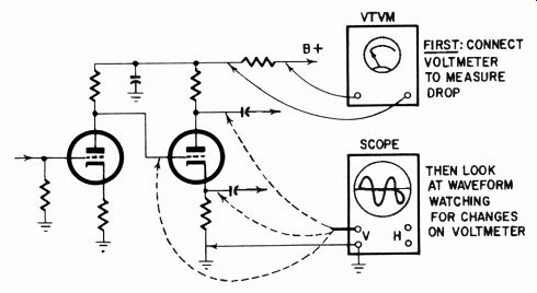
Fig. 104. Another method of using a voltmeter to check whether a scope disturbs
the circuit.
Sometimes the loading effect of the voltmeter does not alter the output voltage, but it can still invalidate the reading. For example, when the amplifier is equipped with a large degree of negative feedback the amplifier input will automatically be adjusted so that the output remains the same. The wave may change slightly (which can be observed on a scope) or it may only flicker.
Such a change can be detected with a dc meter connected to a high-voltage supply point (the screen of a pentode) which may be adversely loaded in its plate circuit when a scope is applied (Fig. 103) or by measurement of the voltage drop across a series feed resistor in the decoupling circuits of the B-plus supply (Fig. 104). If connecting a scope or voltmeter at some point causes any change in the supply voltage or current, it is evident that the operating condition of the amplifier is disturbed by the connection.
What, as well as how much

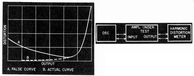
Fig. 105. Mistaken identity about what one is measuring can lead to misleading
results.
What has been said in this section can be summarized in just one sentence. Check what you are measuring as well as how much. The scope must be a complement to measuring techniques.
A run on the distortion characteristics of an amplifier may show that distortion progressively reduces down to the half-power point. Below this point, according to the readings on the distortion meter, the distortion seems to come up as the level is reduced further (Fig. 105). Of course, there are amplifiers in which this really happens. Most probably the distortion meter is not measuring distortion components of the input, but some stray component such as hum. Use of a scope in conjunction with the distortion meter avoids an error of this kind.
Filters can be used to eliminate the hum component so that, in theory, all that remains in the distortion meter residue are the harmonics. Nevertheless a scope must still be used since hum can be introduced through the ground return system in such a way that the filter will not eliminate it.
Some faults in making audio measurements arise from using complicated equipment. It isn't always advantageous, except for repetitive tests under well-established conditions, to use the most complicated or elaborate test equipment you can get. Sometimes this can invalidate the results through faulty ground techniques. For laboratory measurements it is sometimes easier to use simpler and less expensive equipment to avoid ground loops and other spurious effects.