STEREO HAS PUT two speaker systems in our homes. Increasingly, it is also raising the question of why not more than two.
Already it's a fairly common practice to pipe music into various rooms of the house by means of ancillary loudspeakers connected to the stereo amplifier or receiver that drives the main (left and right channel) system. Additionally, proponents of a "center channel" are advising the serious listener to install in his regular listening room a third loud speaker between the left and right sound sources, in an attempt to create the "wall of sound" illusion (or to fill "the hole in the middle"). Yet another group of enthusiasts urges the use of multiple pairs of loudspeakers in the same listening area to achieve reverberatory "surround" effects which approximate the acoustic ambience of a concert hall.
In short, ideas are burgeoning-but before you translate any of them into action, be sure you up date your thinking in terms of the special aspects of solid-state amplifiers. In the past, references to multiple speaker installation invariably included hookup diagrams showing the separate 4-, 8-, and 16-ohm speaker terminals found on amplifiers that used tubes and output transformers. Today's solid state amplifier or receiver, on the other hand, typically has just one pair of speaker terminals per channel-unlabeled as to impedance, at that. Connecting an unlimited number of speakers in parallel across any amplifier's speaker terminals invites disaster. With solid-state units, excessive loading can destroy the output transistors (or, at best, cause speaker line fuses to blow or circuit breaker to chatter). Obviously, the subject of multi-speaker hook ups needs re-examination.
When considering speakers for secondary locations (e.g., den, kitchen, or bedroom), the question naturally arises: need they cost as much as those in the main listening room? They can, of course; but inasmuch as listening in these secondary areas will generally be a casual experience, more modestly priced speakers may serve the purpose. If, however, the proposed arrangement includes the possibility of operating only the secondary pair of speakers (with the main stereo pair turned off), choose extension speakers whose power-handling capacity is large enough to absorb all the energy that your main stereo amplifier may feed them.
Extension Speakers--Some Music Wherever You Go--Consider too the efficiency of the secondary loud speakers: how loud will they sound for a given amplifier's power output? Current loudspeakers on the market include efficiency ratings that vary from be low 1% to higher than 10%-a variation to be found among expensive systems as well as lower-cost models. Ideally, the efficiency of the secondary system should be approximately equal to that of the primary system, thus obviating the need to rush to the main volume control to make readjustments every time the sound is switched from one system to the other.
Should you have acquired secondary speakers of widely differing efficiency from the main set, you can, however, adjust their sound level by means of L-pads wired to them. Such pads should be selected to match the impedance of the speaker each will control. The general method of interconnecting an L-pad is shown in Fig. 1; detailed instructions usually are provided by the manufacturer. Examples of such pads include 'the Switchcraft Part No. 651 (for 8-ohm speakers) and No. 651-S (for 16-ohm speakers). These are equipped with standard wall plates and can be mounted in standard outlet boxes, much as an electrical outlet or switch. Similar products are offered by Lafayette; and a new series of level controls employing autotransformer action has been introduced by Jensen in power ratings of 10 watts and a nominal impedance of 8 ohms. One of the models in this series is the LT-810 level control, which provides attenuation in 3-dB steps up to 27 dB, plus an "off" position.
The switching and wiring arrangement shown in Fig. 2 is both simple and effective. It permits you to connect two sets of speakers, and select either system A, system B, or systems A and B simultaneously. Except for the pad on system B, many re cent amplifiers and receivers have such a facility as a built-in feature. If yours does not, you can make the hookup yourself, but first observe certain pre cautions.
1. Determine the lowest load impedance which may be placed across a channel of your amplifier or receiver without endangering the output transistors. For most units, this will be 4 ohms. If in doubt, check the instruction manual or query the manufacturer or dealer.
2. Determine the impedance of your primary speaker systems.
3. With this value in mind, select secondary speakers having an impedance which will permit you to employ the hookups of Figs. 2, 3, 4, or 5, de pending upon your set of circumstances.
4. For the hookups in Figs. 2, 3, or 4, purchase an inexpensive three-position switch such as the Mallory 3223 J (double-pole, three-position rotary switch). For the hookup in Fig. 5, choose a switch like the Mallory 3243 J (four-pole, three-position rotary switch). Note that one of the four poles avail able would then not be used--I couldn't find a three-pole, three-position switch in the catalogues.
From one standpoint, solid-state amplifiers offer an advantage over tubed units in multiple speaker hookups. Generally, a solid-state amplifier will de liver its greatest power when connected to its lowest permissible load. For instance, an amplifier capable of delivering, say, 30 watts per channel into an 8-ohm load may be expected to deliver 40 or more watts when loaded with a 4-ohm impedance.
Thus when additional speakers are connected across the output terminals, thereby reducing the net load presented to the amplifier (8 ohms in parallel with 8 ohms equals 4 ohms, etc.), more power will be available to drive the extra loudspeakers.
As mentioned above, this approach must not be carried to extremes, since there is a minimum load impedance below which operation of the output stages of the solid-state amplifier may fail, some times destroying the transistors themselves in the process. That is why Figs. 3 and 4 include series resistors. In Fig. 3, the combined impedance of an 8-ohm and 4-ohm loudspeaker would be approximately 2.7 ohms, were it not for the additional resistor inserted in series with the 4-ohm speaker when both systems are to operate simultaneously.
In Fig. 4, the net impedance of two 8-ohm speakers in parallel would be 4 ohms, or half the safe 8-ohm value, were it not for the addition of the 8-ohm series resistors in the circuit when both speakers are to play.
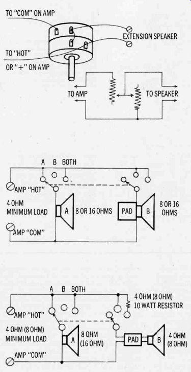
----------- Fig. 1. Wiring diagram and equivalent schematic of an L-pad
used as a level control for an added loud speaker.
Fig. 2. Switching circuit for local (A) and remote (B) speakers, per channel, where both speakers are at least 8-ohms impedance, and amplifier can sustain a load as low as 4 ohms. Switch used is a two-pole, three-position type (see text).
Fig. 3. Switching circuit for local (A) and remote (B) speakers, per channel, where primary speaker is of 8-ohms impedance, and secondary speaker is of 4 ohms. Amplifier requires 4-ohm load or greater.
Read values in parentheses together for alternate situation in which this diagram applies.
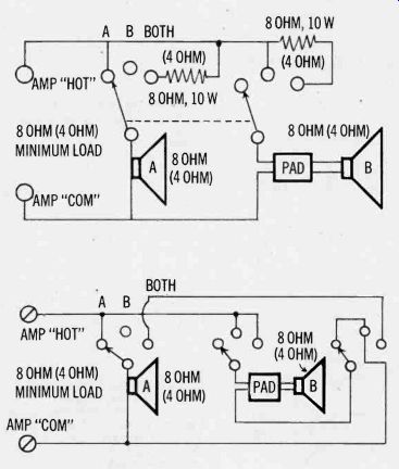
------- Fig. 4. Switching circuit for local (A) and remote (B) speakers,
per channel, where each speaker impedance is lowest value permitted for
the output of the amplifier being used. Read values in parentheses together
for alternate setup in which diagram applies.
Fig. 5. This alternate setup to that shown in Fig. 4 eliminates the power resistors but requires a more elaborate switch. Note that in extreme clockwise position of switch, speakers are in series (rather than in parallel), thus presenting a doubled load impedance to the amplifier output.
Many purists will object to the insertion of series resistors as shown in Fig. 4, arguing that such modifications will lower the normally high damping factor associated with quality solid-state amplifiers. In other words, the speaker so encumbered will "look back" into a driving impedance of 4 or 8 ohms-plus, instead of into the fraction of an ohm internal impedance present at the speaker terminals of most quality solid-state amplifiers. Such an alteration of driving conditions very often reduces the transient response capabilities of the system (sharply percussive attacks become "muddied"). For this reason, Fig. 5 is presented as an alternative, even though it demands a somewhat more complex switching arrangement. Switchcraft's Model 670 Stereo Selector Switch is ideally suited to the hookups of Figs. 2, 3, and 4, containing two of the circuits shown (enough for both stereo channels of your system). If this product is to be used, however, make certain that the manufacturer of your amplifier permits "common" terminal connection of the return lead of speakers of left and right channels.
Some amplifier circuits are not designed to permit such common connection, in which case two separate switches such as those shown in Figs. 2, 3, and 4 would have to be used-one for left channel selection, the other for right channel.
If you are currently planning a complete stereo system installation and do not yet own any loudspeakers, there is some "impedance planning" you can do at the outset if you plan to incorporate two or more pairs of systems. Suppose, for example, that you will ultimately want four pairs of loud speakers, and that there may even be occasions when all four systems will be in use at one time.
Such a situation is not at all farfetched, for you might discover the benefits of "surround" speakers in your main listening area (a second pair of "enhancing" speakers mounted behind the listener, and attenuated somewhat with respect to the primary speakers by means of suitable L-pads). In addition, you might want a pair of inexpensive speakers in your den or recreation room and a fourth pair in a bedroom.
Based upon the connection principles already discussed, such a situation is best met by the use of 16-ohm loudspeakers, since connection in parallel of four such loudspeakers (per channel) would yield a net impedance of 4 ohms, a safe lower limit for most stereo amplifiers. In choosing such a high impedance for your speakers, however, bear in mind that your amplifier will produce its least maximum power when feeding only one pair. It is therefore important to choose an amplifier whose power rating at 16, ohms is adequate in terms of your main listening area and your personal loud ness preferences. To date, most manufacturers of amplifiers quote power ratings at 8 ohms or at 4 ohms. If queried, however, reputable dealers and manufacturers will translate these figures into 16-ohm power ratings.
Correct phasing of the added speakers is as important as it was for the original left- and right-channel systems. Where secondary pairs are used in other locations, the new pair need be phased only with respect to itself. Where a pair of "surround" speakers are used in the main listening area, they must be phased not only with respect to each other but with respect to the original left- and right-channel speakers as well.
Many loudspeakers are now marked for polarity (a plus sign, or a red dot, or the impedance rating number next to one of the terminals denotes connection to the "hot" or "high" terminal of the amplifier output). If your speakers are so coded, simply follow these indications for all parallel wiring.
If no polarity is indicated on your speakers, deter mine phase by first connecting the new pair of speakers in an arbitrary fashion and listening to a monophonic program source intently. Note the presence or absence of sound seeming to emanate from between the new pair of speakers. If uncertain, reverse the connections to the terminals on one speaker only. Whichever connection yields the strongest bass response and the most defined "center" sound is the proper connection for in-phase operation of the new system.
Center Speakers More Music Where You Are
The so-called center channel approach towards achieving an enhanced stereo effect has undergone alternating periods of popularity and disfavor. De rived from the basic two channels of stereo by a process of mixing, the center channel was originally advanced as a technique for overcoming exaggerated separation (the "hole in the middle"). The center channel was also found to enhance stereo solidity and to help create a wall of sound.
By center channel I do not mean the "mixed-bass" technique used by some manufacturers of stereo consoles or package sets. In this compromise approach, all low frequencies (whether from left- or right-channel program) are mixed together and fed to a single woofer or bass speaker, usually mounted in the center of the cabinet. Left and right speakers then consist merely of inexpensive midrange and/ or high frequency loudspeakers which are not called upon to deliver any bass at all and can there fore be fairly small-sized units. Although proponents of mixed bass maintain that frequency separation is not essential at low frequencies, in controlled listening tests I and others have repeatedly disproved that premise.
In speaking of the center channel, I am assuming a basic system in which two normal wide-range speaker systems comprise the left and right channels. A center speaker is fed a judicious amount of left-and-right combined information merely in or der to "fill in" and enhance the over-all stereo effect. Too little center channel contribution will re main unnoticed, while too much will detract from the needed separation effects inherent in stereo re production. Quantity of center channel audio needs to be carefully set by means of an L-pad.
In the days of vacuum tubes and more particularly of output transformers, it was relatively easy to create a third channel output from a stereo amplifier. A bit of rewiring of the 4-, 8-, and 16-ohm speaker terminals was all that was required. With today's solid-state amplifiers (equipped with only a "hot" and "common" terminal per channel), direct derivation of a third channel suitable for driving a speaker is not possible unless the manufacturer of the amplifier has made specific provision for this feature.
To create a mixed channel signal source with the newer amplifiers it may be necessary to use a third power amplifier in conjunction with the resistive mixing circuit shown in Fig. 6. Since the extra amplifier is only a mono power amplifier (no controls are necessary), many inexpensive (under $100) solid-state amplifiers, including even public ad dress types, or even a long discarded tube amplifier, will do very well for the purpose. Furthermore, since you will not be relying upon this amplifier for anything but a "fill in" function, its power-handling capacity need not be anywhere near that of your main stereo amplifier. Experiments have shown that in an average installation, with reason able separation of left and right speakers, power fed to the center channel should be about 10 dB be low that fed to the side channels. Ten dB represents a power difference of ten to one-which means that if your stereo amplifier is capable of delivering, say, 20 watts per channel, you will probably want to feed not much more than two watts of audio power from the extra center amplifier to the center speaker (assuming this third speaker has about the same efficiency as the other two). If this third amplifier has its own input level control, you can even dispense with the control shown in Fig. 6, since level setting--a one-time operation--can be accomplished by means of this auxiliary amplifier's own level control.

Fig. 6. Wiring diagram and equivalent schematic for mixing left and right
signals to get a "center fill" to feed to an auxiliary amplifier
and speaker. If auxiliary amplifier has volume control, eliminate the 1
megohm control and substitute a fixed 1-megohm resistor, wired in as shown
by the dotted line on the schematic.
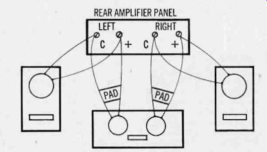
Fig. 7. Assuming your amplifier can handle the net load impedance presented
by this arrangement, a center fill sound source can be set up by mounting
two speakers in one enclosure and wiring them as shown. This hookup does
not re quire a third amplifying channel but does call for L-pads wired to
the center speakers.
If the thought of another piece of electronic equipment discourages your third channel aspirations, there is one other alternative, even with solid state amplifiers. Try mounting two inexpensive six-or eight-inch loudspeakers in a single speaker en closure. Parallel one of them to the right channel amplifier output and the other to the left channel amplifier output, using L- or T-pads as shown in Fig. 7. Since both of these additional loudspeakers are in such close proximity to each other and mounted in the same enclosure, an acoustic rather than an electronic mixing of left and right channels will take place and an effective "third channel" fill will result.
Level setting of third channel output is really the key to success of all third channel endeavors. Do not make the mistake of running the third channel at too high a level as this will tend to reduce the stereo illusion. Correct level set can be described as that level which maintains full stereo effect but also significantly improves the desired illusion of a total wall of sound.
As I have implied, there is no need to purchase a third channel speaker capable of bass response down to 50 or 40 Hz. It is presumed that your initial setup provides sufficient bass and loudness. The real criterion for a center channel speaker is that it be as distortion free as possible over its rather limited frequency range. Even this requirement may be modified, for the third speaker will be contributing only about 5 to 10% of the total sound in the room. Thus, even in the extreme case of a center speaker's having 20% distortion of its own, the net, harmonic distortion contributed to the total sound will be only 1 or 2%.
With all this "paralleling" of loudspeakers-for any of the above applications-there is one more precaution that should be observed. We have been speaking of the impedance of loudspeakers as a hard and fast number of ohms. The truth is that the impedance of a loudspeaker is a rather nominal figure. Usually, a manufacturer of loudspeakers will state impedance at a single frequency, say 400 Hz.
In many cases, the measured impedance will vary above and below the nominal value, often by a wide margin, at frequencies other than 400 Hz. As a rule, impedance runs higher at the very high frequencies, dips somewhat in the middle range, rises sharply at the resonant frequency of the speaker, and falls sharply at frequencies below resonance.
Applied to older vacuum tube amplifiers, these excursions in impedance merely meant a reduction in optimum power transfer from amplifier to speaker.
In solid-state amplifiers, the consequences may be more serious. If the impedance of a loudspeaker at a particular frequency dips sharply below its nominal value, it may be so low as to exceed the safe lower limit of the amplifier and excessive output transistor current may flow, ultimately damaging the output circuitry of the amplifier. Normally, the dip in impedance of most loudspeakers is not so great as to cause damage. Assume, for example, that a loudspeaker's nominal impedance of 8 ohms actually drops to 5 ohms at a frequency just below resonance. Since most amplifiers can be safely operated with a 4-ohm load, no problem arises. Now, connect two such speakers in parallel. The combined nominal impedance will be 4 ohms-ordinarily safe. However, at the sub-resonant frequency where each loudspeaker exhibits an impedance of only 5 ohms, the combined parallel impedance will be 2.5 ohms-which may fall below the safe limit for many solid-state units. Fortunately, very little program material contains an excessive amount of sub-resonant frequency material; and when it does occur, it is usually short-lived. Still, the impedance characteristic of a loudspeaker (or of paralleled loudspeakers) should not be ignored altogether.
Many manufacturers, aware of this potential hazard, have begun publishing curves of impedance rather than stating the impedance simply at a single frequency. Such a curve would look about like that shown in Fig. 8. More significantly, some manufacturers are tightening their specifications and designs to insure that the impedance of their loudspeakers never goes below the stated nominal impedance. This trend bodes well for the future health of our output transistors and their associated circuitry.
Your amplifier was designed to drive at least two pairs of loudspeakers and perhaps more. By taking advantage of its built-in capability (either by adding speakers in other locations or by enhancing the sound in your main listening area), you will be utilizing your equipment for all it's worth and increasing your own listening pleasure for a relatively small additional investment.
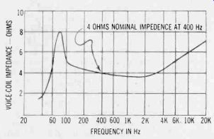
Fig. 8. Impedance curve of a loudspeaker taken over its full range shows
how load varies with frequency.
-----------
(High Fidelity, 1976)
Also see:
CUSTOM TAILORED SOUND--Special equalizers and how they improve speaker sound; the experience of ''tuning" a room.
BUYER'S GUIDE TO SPEAKER SYSTEMS--A complete listing of available models from various manufacturers giving important design and performance features, sizes, prices.