A "Low-End" Receiver that's Far More
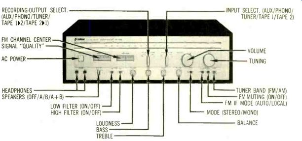
Yamaha Model CR-640 stereo FM/AM receiver, in simulated wood-grain cabinet. Dimensions: 20 by 6 1/2 inches (front), 15 1/4 inches deep plus clearance for controls and connections. AC convenience outlets: 1 switched (200 watts max.), 2 unswitched (200 watts max. total). Price $410.
Warranty: "limited," three years parts and labor. Manufacturer: Nippon Gakki Co., Ltd., Japan; U.S. distributor: Yamaha International Corp., P.O. Box 6600, Buena Park, Calif. 90620.
One of Yamaha's more radical ideas is that the basic specifications of the lowest-priced product in its line should match those of its more expensive ones. The premium components may offer more features or power, but the bandwidth and distortion specifications of the new CR-640 receiver are precisely the same as those of the top-of-the-line CR-2040. Each claims 0.02% THD from 20 Hz to 20 kHz; each has the same damping factor, the same sensitivity, and pretty much the same frequency response and signal-to-noise ratios. And although the higher-priced receivers' tuner sections afford somewhat better stereo sensitivity, slightly lower distortion, and improved ability to reject spurious noise, there are no gross differences in tuner performance.
The Yamaha CR-640 is what we have come to call a modestly priced receiver. It is rated at 40 watts (16 dBW) per channel-certainly no Charles Atlas but probably adequate for the vast majority of installations. It meets its power spec with a generous margin of safety both dynamically and on a continuous-power basis. Clipping does not occur until the output is 1/4 dB greater than spec into 8 ohms, and 1 dB more is available when driving 4-ohm loads.
Total harmonic distortion is virtually nonexistent at both the 0-dBW (1-watt) and 16-dBW (40-watt) output levels. (Note that this is "true" harmonic distortion, not the total-harmonic-distortion-plus-noise figures that we have used in the past. In this case it consists mostly of second and third harmonics, with just a hint of fourth at full power and 20 Hz.) Low-frequency damping factor is more than sufficient for any system; the gauge of the speaker wire will probably be the limiting factor.
The phono preamp encompasses the entire band from 20 Hz to 20 kHz with virtually perfect flatness and virtually no distortion. Mid-frequency overload is more than adequate; while the circuitry has somewhat less headroom at high frequencies, it is unlikely to be taxed by the signal on any commercial record. Phono noise level is low, sensitivity adequately high. The input impedance is not "classic"--it cannot be modeled by an ideal parallel combination of resistance and capacitance. Perhaps as a result, the phono cartridge we used did not produce the best response we have heard from it. But differences in this respect are subtle; use of another cartridge might have altered our opinion.
The frequency response from the high-level inputs remains utterly flat from below 10 Hz to the upper limits of audibility. It can be modified by switching in the sharp low filter (whose cutoff frequency is sensibly chosen at 24 Hz) or the high filter, which is less effective. For additional tonal modification, the shelving tone controls provide symmetric boost and cut of sufficient magnitude to please even tone-control-happy listeners-which we are not.
The independent dual selector switches are a welcome surprise-at least to us. One selects the program for listening; the other picks that to be recorded. You not only may dub between two tape decks, in either direction, while listening to FM or whatever--a common provision on high-tab receivers though infrequent in this model's price class-but can record from any source at all while listening to the same or any other source. Greater flexibility than that defies imagination. Measurements made on the tape-recording-output circuitry indicate that it is compatible with audiophile decks.


-------------------------
Reading the Numbers: An Update
You will find a number of changes in this issue when you look at the test data. Some represent new measurements; some involve new ways of looking at old ones-either in terms of the way a measurement is made on the test bench or in how we report the lab findings in our pages. All, we believe, will be useful to our readers, whether they are technically inclined or music lovers in search of better sound systems.
Conflicting criteria are, in several respects, a way of life in the equipment testing program of a magazine such as ours.
We would like to be as complete as possible in our documentation: yet too much information can easily be, for the nontechnical reader, even more confusing (and therefore even less useful) than too little. We would like to keep our ways of measuring and reporting utterly consistent so that comparisons between products may be as direct and unequivocal as possible; new and potentially more revealing test techniques are always coming to hand, however, while some of the old ones tend to lose their meaning as the problems they once documented are solved. There are, in addition, conflicts within the technical community itself about the comparative value and meaning of many tests; between the extremes of the tests whose virtues are familiarity and ease of measurement rather than precise revelation of audible quality, and those almost faddist approaches that fascinate briefly with the promise of saying all that need be said but that prove on cooler consideration to speak less than plainly, lie a host of opportunities for disagreement.
The current changes reflect these conflicts. You will find that many of the measurements-particularly for separate channels in areas where performance is very consistent between channels in today's equipment-have been dropped in favor of data that we have not presented at all in the past. And there are changes in the way some of the remaining measurements are made, with varying effects on the comparability of numbers. You will find that we are increasingly adamant about avoiding data that represent electronic achievements rather than sonic quality.
In FM tuner sections, for example, our intermodulation measurements have been made in mono only and have followed the IHF spec in looking only for the first-order distortion products-the "difference tone." Other spurious products within the audio band can be even higher in level, however, and we herewith begin reporting the total of these products (as measured in the mono mode), which we believe to be a more accurate indication of signal quality. These total numbers can be several times as high as the conventional measurements and therefore do not bear comparison with the IM distortion in past reports or on spec sheets. We also are adding what the IHF calls a stereo IM measurement. In reality, it documents intermodulation between a signal tone and the stereo pilot tone at 19 kHz, so we will call it "stereo pilot inter-modulation." Formerly, this sort of intermodulation contributed significantly to what we called (with admitted inexactitude) "10-kHz harmonic distortion," which lumped together a variety of high-frequency and ultrasonic "garbage" components as measured by a conventional THD + N distortion analyzer. In effect, we have singled out the most significant of these components so that the reported figure will better reflect audible performance. At the same time, we have altered the test frequencies for THD + N to conform to the IHF spec-100 Hz, 1 kHz, and 6 kHz-and simplified the test results by reporting on only one channel in stereo.
An important addition is the figure for THD + N at 50 dB of stereo quieting (the sensitivity rating point) as an index of how "clean" the audio will be when signal strength is barely enough to keep noise reasonably low. (The other THD +N measurements are made at considerably higher signal strengths.) A 'perfect" score would be about 0.3% since that is the percentage equivalent of the noise component in the THD + N when the noise is at-50 dB. And we have added a figure for muting threshold so you can judge at what performance level you will have to forgo the muting feature.
In the amplifier data, we are continuing to drive both channels simultaneously in the high-power tests to put maximum stress on the circuitry, though we report on only one. The major change is in our approach to distortion, where we are altering both measurement techniques and reporting practice.
Within the last year or two, increasing quantities of experimental evidence have shown that, given flat frequency response and reasonably low steady-state distortion, the subtle differences that the "experts" (self-styled or otherwise) have found between amplifiers are not attributable to the amplifiers themselves and that the more carefully controlled the experiment, the more unequivocal its demonstration of this fact. There are differences, however. Some are attributable to the way in which a given design may mate with other equipment connected to its input or output stages; some (transient intermodulation is the most talked of) are attributable to other than steady-state effects; some seem to be limited to the ear of the individual beholder. In any event, we can find no unassailable reason to assume that the current insistence on ever-lower steady-state (conventional THD or IM) measurements has any real sonic meaning. Nor, since they ultimately document the same basic nonlinearities, do we see any reason to continue separate THD and IM measurements, which are largely redundant with current equipment.
In graphs and data, beginning in this issue, we are ignoring as negligible any distortion below 0.01%. Probably the threshold of perception is very much higher, but this admittedly arbitrary cutoff will allow us to include any data of importance without getting into the realm where distortion numbers become dubious in the measuring as well as useless in the listening. Many manufacturers, we are sure, will continue to insist on their accomplishments in that area; we can only reply, as we have in the past, that we are interested in sonic quality--not electronic virtuosity as such.
We will continue to use both THD and IM measurements as
investigative techniques, though the precise format in which we couch the numbers probably will be subject to experiment over the next few months until we are convinced we are expressing the results with maximum intelligibility and usefulness. Since the results will not give us the conventional inter-modulation curves from which to judge maximum power capability into various resistive loads (the only unique capability of the IM curves in our past format), we will show clipping points with the three standard resistive loads-4, 8, and 16 ohms-instead.
At the input end, we are adding a measurement of phono cartridge loading. Following the IHF amplifier standard, we will determine what values of resistance and capacitance are presented by the phono input and report them as an aid to those readers looking for an ideal pickup/preamp match.
(See Edward J. Foster's article in this issue.) Where the input impedance is complex, implying different resistance and capacitance values at different frequencies and therefore problematic matching, we will show only the 1-kHz resistive value.
Tape equipment reports now provide a lot more beneficial information than heretofore. Diversified Science Laboratories, where the decks are measured for us, has developed methods for measuring meter ballistics so that our comments on this crucial area can be more precise. It also has begun measuring the midrange overload point (3% distortion) with each of the tapes used in testing the deck. This-in combination with the meter data-provides information about effective dynamic range (as opposed to S/N ratio with respect to a fixed standard recording level) and best use of the deck. To help get a fix on the overload properties of the design, we have added a figure for the mike-input clipping point.
The S/N ratio figures themselves-which now, also, are given for all the reference tapes-are A-weighted. The CBS curve, which we have been using, is a more elegant approximation of actual noise audibility; tests have shown, however, that the numbers delivered by the simpler and much more widely accepted A-weighting curve are very closely related to the CBS results. In addition, they are consistent with those measured in amps and preamps, employing the same technique. While the numbers will be reasonably consistent with those we have been publishing, you should be aware that differences of a few dB might result if a given product were to be measured both ways.
One of the reasons for our documentation of deck behavior with more than one tape is the change, in cassette equipment, from ferric to chrome or chrome-equivalent tapes as the basic standard for record/play measurements. When we began testing these decks, ferric tapes were, indeed, standard; now-at least for the quality performance that justifies their inclusion in our test reports-chrome is the standard. In a few instances, ferri-chromes deliver even better performance, and decks capable of using the metal alloy tapes will be the subject of reports later this year. So, as an aid in comparing current results with past reports and in grasping the tape's role in deck performance, key data are given for all tapes. And, aware that interchannel consistency has improved markedly in recent years, we have dropped measurements for the second channel of stereo decks in all areas except frequency response, where differences between channels can be quite revealing.
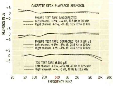
One final major change is illustrated in the accompanying graph. We always have tested cassette playback response with the Philips test tape, since Philips is the inventor (and therefore arbiter) of the format. But for several years, and by general agreement within the industry, the vast majority of decks have been "nonstandard" in one respect: They have used a 3,180-microsecond bass equalization curve to avoid the low-frequency distortion that could result from the more exaggerated pre-emphasis of the original Philips standard. A regular feature of our deck reports therefore has been a verbal "translation" of the data derived with the Philips tape into its equivalent response with the de facto 3,180-microsecond standard. We now are using TDK test tapes that are recorded to this standard and need no translation.
The three pairs of curves were made on a single deck. The top pair appears as it would have in past reports-the data read directly from the output meter. The second pair represents the translation-the effective response on which we would comment in the text of the report. The third is a direct reading from the TDK tape. Note that the test frequencies are different: The Philips tape goes about one-third octave lower, the TDK one-third octave higher. And while the shapes of the TDK and corrected Philips curves agree reasonably well, the match is not perfect. The problems of producing and working with test tapes being what they are, exact agreement is virtually impossible; the differences may be taken as an index of the degree of accuracy to be expected in such tests.
In particular, a gradual high-frequency rolloff is discernible in the TDK results (and repeated on other decks with this tape). This, like the bass "boost" in the Philips results, will require interpretation, but the new curves have the distinct advantage of allowing comparisons between decks at higher frequencies than before-a more critical range than the deep bass where we are dispensing with some data.
CASSETTE DECK PLAYBACK RESPONSE
PHILIPS TEST TAPE (UNCORRECTED) Left channel: +21,-Va dR 31.5 Hz to 10 kHz
Right channel: +31,-Va dB, 31.5 Hz to 10 kHz
------------
PHILIPS TEST TAPE, CORRECTED FOR 3.180 µS
Left channel: +11,-31 dB, 31.5 Hz to 10 kHz Right channel: +u,-11/4 dB, 31.5 Hz to 10 kHz TDK TEST TAPE 6.180 µS) Left channel: +11/4,-21 dB, 40 Hz to 12.5 kHz Right channel: +W,-5 dB, 40 Hz to 12.5 kHz 20 50 100 200 500 1K 2K 5K 10K 20K FREQUENCY IN HZ
----------p42
-------------
Yamaha CR-640 Receiver Tuner Section Capture ratio 11/4 dB Alternate channel selectivity THD + N at 100 Hz at 1 kHz at 6 kHz stereo
0.29%
0.088%
0.15% stereo*
0.45%°
0.20%
0.26%° 2'/z dB° 46'/x dB 60Y4 dB* mono
0.27%
0.066%
0.13% IM distortion (mono) 0.068%
Stereo pilot intermodulation AM suppression Pilot (19 kHz) suppression Subcarrier (38 kHz) suppression S/N ratios (at 65 dBf)
stereo mono 68'/4 dB 80 dB
0.080%°
0.098%
0.247% 761/r dB 60 dB
>85 dB 69 dB 80 dB' Muting threshold 23'1 dBf mono°
0.27%°
0.098%
0.16%°
*Asterisked data were measured in the DX (long-distance)
mode; all others were measured in the local mode.
Amplifier Section
Manufacturer's rated power 16 dBW (40 watts)/ch.
Power output at clipping (both channels driven)
Into 8 ohms 17 3/8 dBW (52 1/2 watts)/ch.
into 4 ohms 18 1/4 dBW (68 watts)/ch.
into 16 ohms 15 1/4 dBW (34 watts)/ch.
Dynamic headroom (at 1 kHz) 1 dB
Frequency response +0,-% dB, <10 Hz to 21.3 kHz
+ 0,-3 dB, <10 Hz to 93.5 kHz
Input characteristics (re 0 dBW; noise A-weighted)
Sensitivity S/N ratio phono 0.405 mV 77 dB aux, tape 19.3 mV 85 dB
RIAA equalization +-34 dB, 20 Hz to 20 kHz
Phono overload (clipping) 192 mV at 1 kHz
Phono impedance 50K ohms at 1 kHz (complex)
Harmonic distortion (THD; 20 Hz to 20 kHz) at 16 dBW (40 watts) output at 0 dBW (1 watt) output
<0.014%
<0.012%
Damping factor at 50 Hz 99
-------------
A second goody not usually found even on expensive receivers is the separate loudness control. Note that we say "control," not "switch." Theoretically, the degree of loudness compensation should vary with the listening level: The greater the reduction from "real" sonic levels, the greater the compensation. In the Yamaha CR-640, you first turn up the LOUDNESS all the way and set the volume control to the highest listening level you'd be likely to want-which will, of course, depend on your taste, the efficiency of your speakers, and the acoustics and size of your room. For subsequent level adjustments, turn down the LOUDNESS, which boosts the lows and, to a smaller extent, the extreme highs relative to the midband to maintain a natural-sounding balance. To our ears, the balance is plausible indeed. We don't usually wax eloquent about such circuitry, but this control strikes us as considerably more useful than the run-of-the-mill variety.
Yamaha's tuner design emphasizes simplicity of operation, and some audiophiles may find that it actually does too much for them. The tuner can operate in two IF modes (surprising at this price): "DX" and "LOCAL." The DX mode-short-wave jargon for distant transmission-is the more selective of the two. LOCAL, as the name implies, is for strong-signal reception. In normal operation, the tuner automatically chooses DX whenever the signal level is low.
Lab data show the DX mode to be 3 to 4 dB more sensitive than LOCAL. Response and S/N ratios are virtually identical.
Capture ratio and distortion are, predictably, better in the wideband LOCAL mode. The DX mode both reduces IF bandwidth and blends the two stereo channels to decrease background noise. In the CR-640, this blending affects the entire band-rather than the high-frequency region alone, as in most BLEND switches-and chops the channel separation to a uniform 8 dB. (In LOCAL, it is better than 40 dB over the important part of the spectrum.) We can follow Yamaha's logic part way: The DX mode is most useful when receiving weak stereo broadcasts, and since they are likely to be noisy-some channel blending will make them more listenable. This does not allow, however, for occasions when one wants the added selectivity of the narrow bandwidth (to reject an interfering station on a nearby channel) even though the signal strength is relatively high and the blend therefore unnecessary. We could put up with the slightly higher DX distortion (it's still very low), but in such a circumstance we would prefer not to give up stereo (or even the near-stereo of a conventional BLEND) in favor of this blend's near-mono. Although the mode button can force the CR-640 into LOCAL, it cannot "select" DX; the only alternate setting (AuTO) automatically goes into DX operation when the signal strength is low and chooses LOCAL on strong stations.
This degree of automation does reduce one's options.
That aside, we find the tuner section very good indeed. Distortion is low, response excellent. AM suppression (a new measurement) is first-rate. That, together with the good cap-ture ratio, bodes well for good reception under multipath conditions-whose control is aided by an excellent SIGNAL QUALITY meter that indicates multipath by fluctuation of its pointer.
The sensitivity of this meter in displaying both the tuning point of maximum signal strength and the antenna heading of minimum multipath is much better than average. The tuning meter is highly sensitive and calibrated (quite accurately) to indicate how far off channel you are tuned. Couple that with a highly accurate dial calibration over most of the band, and it's easy to tell just which station is being received.
On good stations, the CR-640 affords excellent reception; on weak stereo stations, the noise reduction afforded by the DX/blend combination is very effective in improving listen-ability. On very weak stations, we prefer to defeat the muting to prevent the station from sputtering back and forth across its threshold; here, of course, mono reception also is in order.
All this adds up to a lot more than we could logically expect of the low man on Yamaha's receiver-line totem pole-even in view of the company's minimum-performance-standard policy. The tuner section is several cuts above the conventional.
The phono preamp is eminently quiet, and we are highly impressed with the flexibility of the rest of the preamplifier section. We find the loudness control highly satisfactory, the tone controls and low filter L.p to their tasks. And the independent selector switches will bring joy to the hearts of tape recordists.
From what we've seen, the Yamaha CR-640 is unique in its price range.
Also see:
Technics Model SU-001 stereo preamplifier (review, Jun. 1979)