One of the principle circuits used in measurement today is the Bridge, yet it is by no means new. K. T. Wilson explains.
ONE OF THE FUNNY (peculiar) things about electronics is the way so many of the circuits that we use turn out to have been invented long before electronics, as we know it, started. How much effect, do you think, would the work of an electrical engineer who lived between 1802 and 1875 have on modern electronics circuits? He died more than a hundred years ago yet Sir Charles Wheatstone gave his name to one of the most important measuring circuits which we use. What's more import ant, the principle that he used has lead to a huge variety of measuring circuits being devised, all of which are still in use.
WHEATSTONE
The Wheatstone bridge s, of course, the circuit for which Sir Charles is remembered--let's jog our memories a bit on this one. Suppose we have two resistors in series, R1 and R2, and E volts across the two, then across R2, the voltage is E x R2 / R1 +R2.
For example, if the resistors are 3k3 and 6k8 across 9 V, then the voltage across the 3k3 is 9 x 3.3 / 3.3+6.8 which is 2.94 V. Prove it? Dead easy, using a bit of Ohm-sweet Ohm! (Fig. 1)
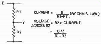
Fig. 1. The potential divider.
Now suppose that we have two of these circuits, potential dividers we call them, one with R1 and R2, the other with two other resistors R3 and R4. Connect them both to the same supply voltage and build a bridge across. A bridge? Yes, a resistor connected across the joins, as shown in Fig. 2--it bridges across between the potential dividers. Problem--how much current flows through this resistor? Well, if you take any old values of resistors, it's quite a difficult problem, one that will give sleepless nights even to most experts. It's easy to solve by a useful fiddle called Thevenin's Theorem, but very tedious by any other methods.
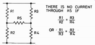
Fig. 2. The bridge circuit.
There is, however, one set of resistance values for which this puzzle clicks into place very easily. These are the values for which the current across the bridge resistor is zero, nil, nothing at all. That condition comes about when the other four resistors in the circuit have values which give R1/R2= R3 / R4. If, for example, R1 is 1k and R2 is 100R, giving a 10:1 ratio, then the ratio R3 / R4 must also be 10:1 if no current is to roll across the bridge. If R4 = 3k3, for example, then R3 must be 33k to give that 101 ratio.
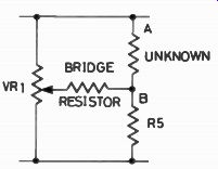
Fig. 3. Using the bridge circuit for measurement.
BALANCING YOUR BRIDGES
Now Wheatstone didn’t come across this by accident. He was working as a consultant for the Post Office, who wanted a method of measuring the resistance of telegraph lines. How do we use Wheatstone's circuit to measure resistance? Easy, just make one of the pairs of resistors a variable. Suppose we redraw the circuit of Fig. 2 so that it appears as Fig. 3, with RV1 a linear potentiometer. The makers of these pots will obligingly supply dials which read the ratio of the resistances each side of the slider, from 0.1 through 1 (middle of the track) to 10. Now to measure a resistance value, all we have to do is to connect the unknown resistance at A and B, either way round, adjust the pot until no current flows across the bridge and read he dial of the pot. In this condition with no current flowing across the bridge, we say that the bridge is balanced. The amount of the unknown resistance between A and B is equal to the value of As multiplied by the potentiometer ratio. For example, if As =10k, and the potentiometer ratio is 0.33, then the unknown resistance must be 10k X 0.33=3k3.
DETECTING THE BALANCE
Easy enough, but how do we tell when there's no current flowing across the bridge resistor? One simple way is to replace the bridge resistor by a current meter, preferably a centre-zero type, and watch it. We can use any old current meter as long as it's reasonably sensitive. It doesn't have to be a precision instrument, it doesn't have to have any scale, as long as that zero position is marked. Meters, even low quality meters, are expensive items, though, so a better scheme is to use electronic methods. There's no reason why we should have to use DC to operate the bridge, so if we use AC at some convenient frequency, say 400 Hz, then we can make use of audio amplifiers to detect the balance. Why choose 400 Hz? Well we want a frequency which is high enough to be easily amplified, with smallish values of coupling capacitors, well above the frequency of mains hum, but low enough so that we don't run into trouble with signal leaking away through stray capacitance. In addition, if we want to use earphones or a loudspeaker to detect when we've reached the balance point, 400 Hz is a frequency to which the human ear is particularly sensitive.
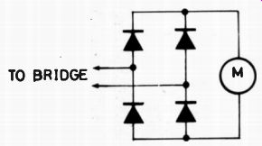
Fig. 4. A rectifier/ meter arrangement for reading balance on an AC
bridge. This is useful only if an amplifier is used between the bridge
output and the detector, because the forward voltage of the diodes will
limit the sensitivity of the detector.
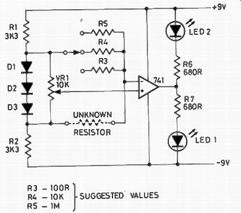
Fig. 5. A sensitive DC bridge using an op amp and LEDs for balance indication.
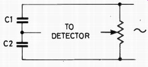
Fig. 6. The De Sauty bridge circuit.
We can use an ordinary voltage amplifier, provided we remember that the input connections have to be to the resistors of the bridge and not to a common earth connection. This way, any AC voltage difference between the two ends of the bridge is amplified and can be detected by an earphone, loudspeaker, or rectifier/ meter combination as shown in Fig. 4. Even more useful is the arrangement called a differential amplifier which, as the name suggests, amplifies the voltage difference between the two ends of the bridge. We can use an operational amplifier for this job, but we have to remember that the operational amplifier has to be correctly biased. If we use AC for the bridge that's easy, but if we want to avoid using a built-in signal generator and make use of the fact that an op amp like the 741 is fully DC coupled, then we run into a slight complication.
We must make sure that the voltage across the whole bridge circuit is small, and that it lies about midway between voltage and earth. The reason is that the inputs to the 741 have to around this mid-voltage, the circuit simply won't work if the inputs are near supply voltage or zero voltage because the circuits inside the IC aren't correctly biased then. Fig. 5 shows a useful bridge circuit which uses DC, with a 741 and a pair of LEDs to indicate balance. With the arrangement shown, LED1 will light if the potentiometer setting is too high, and LED2 will light up if the potentiometer setting is too low.
When the setting is just right and the bridge balanced, both LEDs will glow.
LESSER KNOWN BRIDGE
Mr. Wheatstone's bridge therefore is a quick and simple method of making resistance measurements without using costly meters--provided we have some standard value resistors that we can use as R4 (in Fig. 2). If we can switch in different values of R4, then the measuring range of the bridge can be very great.
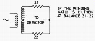
Fig. 7. Transformer-arm bridge principle.
The usefulness of the bridge idea doesn't end there, though, because dozens of people took up the principle of the bridge from where Wheatstone left off. Cast your eyes over Fig. 6, which is a bridge circuit called the De Sauty bridge after its inventor. In this particular version, the two fixed resistors of the Wheatstone bridge are replaced by capacitors, but the ratio potentiometer is unchanged. It won't work on DC, of course, but any sort of AC supply, sine wave, square wave, over a wide range of frequencies, will operate the bridge. As usual, RV1 is operated until the signal output from the amplifier is as low as possible, then the ratio is read from the potentiometer dial. The value of the unknown capacitance is found by multiplying the ratio value by the capacitance of the standard, C1. Sharp-eyed readers will have noticed that this capacitor is not in the same place in the circuit of the bridge as the unknown resistors was in the Wheatstone bridge. That's because capacitors don't behave like resistors--the greater the value of capacitance, the less it hinders the flow of current. Many commercial bridge designs use a bridge which is a combination of the Wheatstone and the De Sauty so that both capacitor and resistor values can be measured with the same instrument.
That's just scratching the surface as far as bridges are concerned. Among the dozens of bridge circuits we can count the Owen bridge, for finding the inductance and the resistance of a coil. This is a type of bridge which is a bit more awkward to use, because there are two adjustments that are needed for balance and they both have to be correct for balance. One, of course, is for inductance and the other for resistance. This two-adjustment business is usually found when inductors are measured and it also has to be used when we take measurements on capacitors which may be leaky, such as electrolytics.
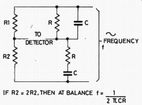
Fig. 8. The Wien bridge circuit.
Looking at just a few more examples of what Charles Wheatstone started, there is the Maxwell bridge for inductance, the Hey bridge for large inductors, the Schering bridge for capacitors, and the Felici bridge for measuring the mutual inductance of transformer windings.
BRIDGE RECTIFIERS
Oddly enough, one of the bridge circuits that is most used these days in commercial bridges has no special name. It's the transformer bridge, and the principle is shown in Fig. 7. The transformer is specially wound, with the secondary windings perfectly matched and balanced to earth so that the signals, at audio frequency, are perfectly in antiphase. For zero output from the AC detector, the two impedances (resistors, inductors or capacitors) must be exactly identical. To use this system as it stands, of course, we would have to be able to balance any unknown with an exactly equal standard, so what is done is to make the transformer ratio variable, by winding the transformer in the same way as we wind a potentiometer, with a sliding contact. We can then go back to the familiar method of having a standard and a ratio once again. This alas, is not a bridge for the constructor because of the need for a very specially wound transformer.
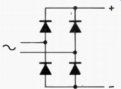
Fig. 9. Modern method of drawing the full-wave 'bridge' rectifier circuit.
Just for a glimpse of a different sort of application, there's the Wien bridge, which has the interesting characteristic that it is balanced at one frequency only.
This is the bridge circuit that is used in so many audio oscillator circuits, in the form shown in Fig. 8. The feedback is exactly in phase only for the frequency:
f = 1 / 2 pi RC
... so that this is the frequency of oscillation.
Just to round off, there is the arrangement of rectifier diodes that we know as a bridge rectifier. It's certainly the same shape as a bridge circuit, but it's hardly in the same league as the real bridges, whose aim is to have zero current passing across the bridge. We wouldn't be happy about a "bridge" rectifier if no current crossed the bridge, because that's the load, just where we want the current! It's not a true bridge circuit, in fact, despite the shape, because current is not free to flow in the two arms, since the diodes in each arm are connected to prevent current flowing right through the arm. Perhaps we shall avoid confusion in future by drawing this full-wave rectifier circuit in the modern form (Fig. 9) rather than in the traditional diamond shape.
(adapted from: Hobby Electronics magazine, Mar. 1979)
Also see: An Introduction to Electronics Test Gear