THE project editor and chief designer Ray Marston takes another look at the hobby scene.
THERE ARE GOOD BOOKS ...
EVERY ELECTRONICS HOBBYIST should make a point of building up a decent collection of electronics reference books. Ideally, you should have at least one really good book that explains the basic principles of electronics, another that outlines the principles of 'advanced' electronics, and one more that gives electronics tables, colour codes, IC outlines, and other pure 'reference' data, etc. The following is our recommended short list.
'Foundations of Wireless and Electronics' by M. G. Scroggie, is probably the best introductory text to electronics ever published. It explains the basic principles of electronics in such a clear manner that even a complete layman can understand it. The subject material of the book spans elementary principles of electricity to fairly advanced electronics.
'Foundations was first published in 1936, and is now in its ninth edition. The book has sold some 265 000 copies, which shows how good it is. The latest edition runs to 521 pages, and costs (mult by 1.4 for dollar) £ 4.45. It is published by Newnes-Butterworth.
Our next recommendation is for 'Electronics --It's Easy'. This is an ETI publication (ETI is the big brother of HE, if you didn't know), and spans the information range of basic principles of electricity to advanced electronics.
It makes an excellent companion to "Foundations--Electronics, It's Easy" was originally published as a 3-volume ETI 'special'. Volume 1 is now out of print, but the whole three volumes are presently being re issued as one single book. Release date should be late August, and price about (mult by 1.4 for dollar) £ 3.
Our final recommendation is for 'Newnes Radio and Electronics Engineer's Pocket Book', 1 5th Edition. This is an excellent pocket-sized (you'll need a magnifying glass to read it) reference book of tables, formulae, IC outlines, data, and basic electronic circuits. The book has been compiled by the staff of ETI, is published by Newnes-Butterworth, and is well worth having.
AND THERE ARE AWFUL BOOKS
As a professional book-worm, I'm obliged to read a great many electronics books. Most are pretty mundane, a tiny minority (like those mentioned above) are very good, and a fair number are, frankly, awful. A couple of weeks back, I read what must rate as the most awful electronics book of all. It's called 'Build Your Own Working Robot', is written by an American named D. L. Heiserman, and is published by Foulsham-Tab. It's well worth looking at, simply because it IS so awful, it must be regarded as a classic of its kind.
The first fourteen chapters of the Robot book describe how to build, for a mere few hundred pounds, a device called BUSTER, which is more or less capable of emulating the actions of one of those cheap (about (mult by 1.4 for dollar) £5) Hong Kong toy cars that change direction whenever they crash into a wall, which is all very amusing if you like that kind of thing. The book really takes off, however, in chapter 15, which has the title HUNGER INTERFACE.
The HUNGER INTERFACE is, to put it as kindly as possible, interesting. Briefly, what happens is that when 'Buster's' 12 volt battery supply falls below 10 volts a pulsed 3 kHz signal is transmitted from its loud speaker, and this signal activates a kind of giant lighthouse (stop laughing at the back there) that is built into one corner of 'Buster's' private room (apparently, 'Buster' is prone to permanent starvation if he moves out of this room).
Buster automatically charges at this lighthouse, like a bull at a red rag, whenever it switches on, and ends up impaling himself on a battery recharging circuit. All very clever.
The lighthouse actually consists of a flashing strobe lamp stuck on top of a five foot pole. At the base of the pole is what is described as a 'nest', which includes (amongst miscellaneous bits of wood and a mirror) a battery charger and a couple of massive metal probes, which get rammed up poor old Buster's charging socket whenever he suffers a slight electron deficiency. In front of the 'nest' are two 8-foot lengths of wooden guide rail, which encompass an area of 32 square feet and, working on the 'pea in a funnel' principle, ensure that Buster gets steered into his nest for a re-charge when ever the need arises. So how's that for American technological know-how? The final chapter of the book describes how to convert Buster into a white-line follower. Which just about sums up the true value of the project that has cost hundreds of pounds to build and sixteen chapters to describe.
To be fair, whatever this Robot book lacks in sophistication of design of its main project is more than compensated for by its author's originality in the use of strange circuit symbols and notations, his sheer guts in presenting photo's of his constructional efforts, and his (thankfully) utter uniqueness of writing style.
As was said earlier, we thoroughly recommend 'Build Your Own Working Robot' as THE most awful book. You simply must read it. Our congratulations to its author, and to the staff of the Ohio Institute of Technology in Columbus, who helped engineer, build, and debug the super white-line follower known as Buster.
RELAY TIMER CIRCUITS
The real 'guts' of Hobby Electronics is the actual building of, rather than reading about, electronic circuits. One of the most useful circuits that the hobbyist can build is the relay timer. It consists of a relay and a few electronic components, configured in such a way that the relay switches on when you press a START button, and then switches off again automatically after a pre-set time delay. The time delay may vary from seconds to days, and the relay contacts can be used to activate such diverse objects as photographic enlarger lamps, porch lights, battery chargers, and tape recorders, etc.
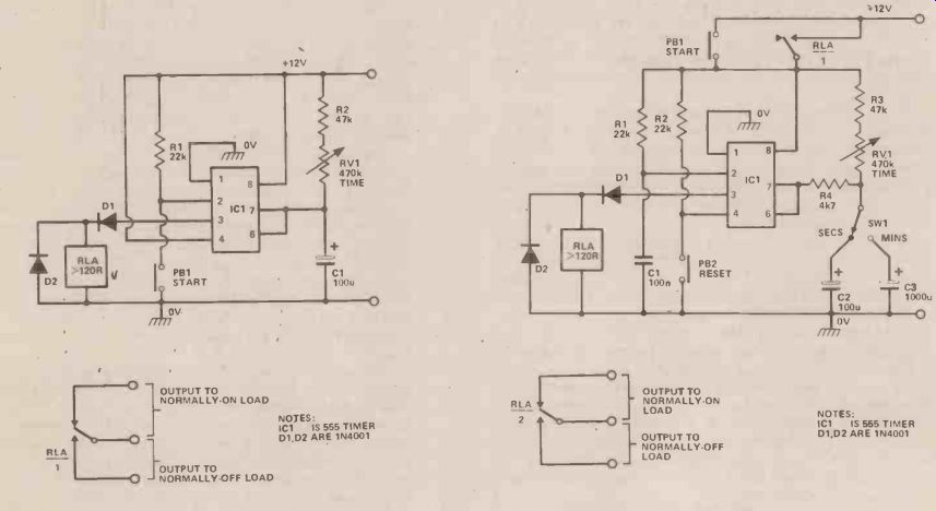
Fig. 1. A simple 6-second to 60-second timer circuit. Fig. 2. A 2 range
6-60 second and 1-10 minute timer circuit.
Figure 1 shows the practical circuit of a simple 6-second to 60-second timer. The design is based on a type-555 timer IC, wired in the monostable or one-shot mode. The circuit starts a timing cycle when push-button START switch PB1 is momentarily operated. Relay RLA immediately turns on, and C1 starts to charge towards the positive rail via R2 and RV1. Eventually, after a delay determined by the RV1 setting, C1 rises to 2/3rds of the supply rail voltage, at which point the IC changes state, the relay turns off, and the timing cycle is complete. External devices can be turned on or off via the relay contacts.
WEAKNESSES
A weakness of the basic Figure 1 circuit is that it permanently draws current from the supply rails, even when the relay is off. Figure 2 shows a 2-range timer circuit that does not suffer from this defect, and which covers the timing range of 6-seconds to 10-minutes. The circuit operates as follows:
When START switch PB1 is momentarily closed a START pulse is fed to pin 2 of the IC via R1 and C1, and the relay turns on. Contacts RLA /1 then change over and maintain the power connections to the circuit even when PB1 is released. The circuit then runs through a timing cycle similar to that already described, but with the period determined by either C2 or C3, until eventually the relay turns off, at which point contacts RLA / 1 revert to their original state and break the supply connections to the circuit. The timing cycle is then complete. Note that this circuit can be turned off part way through its timing cycle by operating RESET switch PB2.
Conventional electrolytic capacitors have very wide tolerances (typically -50% to +100%), and suffer from relatively large and unpredictable leakage currents.
Consequently, simple circuits of the types shown in Figs 1 and 2 can not be relied upon to give accurate timing periods, or to give periods that significantly exceed fifteen minutes or so. Figs 3 and 4 show two high-accuracy long-period timer circuits that do not rely on the use of electrolytics for their timing operations.
FREE RUNNING
In both of these circuits, IC1 is wired as a free-running astable multivibrator. In the Fig 3 circuit the astable frequency is divided down by IC2, a 14-stage binary counter, so that the relay turns on as soon as PB1 is, momentarily closed, and turns off on the arrival of the 8192nd astable pulse, thereby giving total timing periods in the range of 1 to 100 minutes.
The Fig 4 circuit is basically similar to that of Fig 3, except that an additional decade-divider stage is used in position 3 of SW1, thus giving a maximum division ratio of 81 920, and making maximum timing periods up to 20 hours available from the unit.. This circuit is of particular value in giving time-controlled turn-off of battery chargers, etc.
Note in the four timer circuits given that the relay used can be any 12-volt type with a coil resistance greater than about 120 ohms. The relay used in the Fig 2 to Fig 4 circuits should have two or more sets-of change-over contacts.
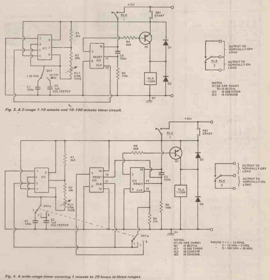
Fig. 3. A 2-range 1-10 minute and 10-100 minute timer circuit.
Fig. 4. A wide-range timer covering 1 minute to 20 hours in three ranges.
(adapted from: Hobby Electronics magazine, Sept. 1979)
Also see:
Thyristors: The Great Gate Story