How to Twiddle Your Electricity Bills
If you're a BRIGHT spark, you will be able to astound your friends with your DIMness simply by building the HE DIMMER.
THE HE DIMMER IS a self-contained unit, fitting into a standard flush, wall-mounting light switch, which can easily replace your ordinary switch.
The printed circuit board was designed so that it fits into an MK rocker type switch although with modifications it should fit any similar sized switch plate.
Design features of the circuit include preset RV1 to allow for component tolerances and individual preferences of light levels, radio frequency interference suppression and an on board fuse to protect the circuit should anything go wrong (and according to Murphy's Law it normally does). Otherwise the circuit is a fairly standard triac/diac power controller which can be used to dim up to 2 kilowatts of bulb power--a fair amount by any standards.
CONSTRUCTION
Fit the PCB to the switch plate (with the switch bits removed) first, before any parts are soldered on, as various holes have to be drilled for screws etc. and this is best done without obstruction.
Once this has been done the parts can be inserted.
Make extra sure there are no solder bridges across the tracks.
The triac is the only polarised component which, of course, must be inserted correctly. If you obtain the same device as ours, the TRI 400-8, then it can simply be lined up the same way as in the overlay i.e., with the heat sink tab closest to the coil L1. If you can't obtain the same triac type, then virtually any type can be used as long as you fit the 3 connections G, MT1 and MT2 in the correct places.
Incidentally, the triac is rated at 8 amps, which is about 2 kW of power. At this rating a fair sized heat sink will be necessary, bolted to the triac. However, at bulb ratings up to 200 watts (adequate for house lighting) no heatsink is necessary.
The coil L1 is not critical and therefore easily made by hand. To construct, Scramble wind 100 turns of 32 s.w.g. insulated copper wire around a 1/2 inch diameter former as in figure 1 (we used the barrel of a pen which was about the right size). Put a spot of glue on the coil of wire and leave it to dry. When dry, slide the coil off the former and fit it to the PCB. Remember to scrape off about half an inch of insulation with wire wool or emery cloth, so that a good soldered connection can be made.
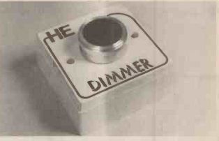
- The HE Dimmer in its wall mounting box. For safety we
recommend using a plastic, flush mounting box.
When the unit is complete it only remains to fit it in the wall and adjust it as described in the section on setting up. Only two connections are necessary --the same two that connect to the back of the existing switch plate and its doesn't matter which way round they are. However, certain safety precautions must be adhered to. If your wall has a metal backing box behind the switch then make sure that nothing on the circuit board touches the box --it may even be necessary to remove it and insert a plastic box in its place.
The PCB has mains voltages on it and for this reason we advise that the board is to be either sprayed or painted with lacquer (nail varnish will do if you have any!???). This will give a degree of protection against shock--which can be fatal.
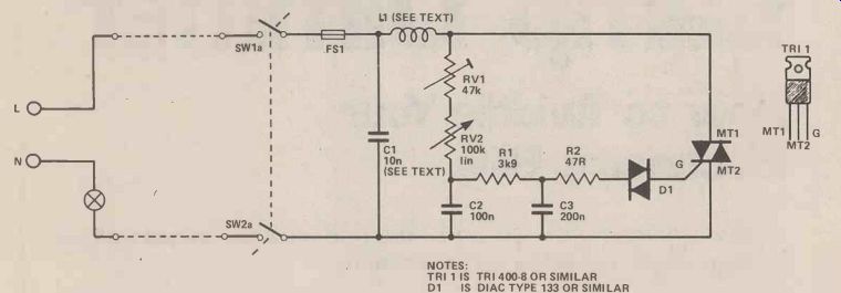
--- Fig. 1. Circuit diagram of the HE Dimmer, for details of the coil
L1 refer to the text and drawing.
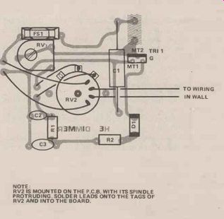
Fig. 2. Overlay diagram for the HE Dimmer, note the position and orientation
of the Diac and Triac, especially if using unspecified devices. NOTE:
RV2 IS MOUNTED ON THE P.C.B. WITH ITS SPINDLE PROTRUDING. SOLDER LEADS ONTO
THE TAGS OF RV2 AND INTO THE BOARD.
SETTING UP
The setting up procedure is simply a matter of adjusting the preset RV1, with RV2 in the low position until the required level of light, in this position, is found. Some people might prefer the main control RV2, to vary from zero to full brightness, but it is probably better to adjust RV1 so that the bulb is just visibly on when the main control is at minimum. This means that it can be visually checked simply by the appearance of the bulb, whether or not the device is off.
Be very careful when adjusting RV1--do NOT use a metal trimmer. Use a plastic one and keep your fingers clear of anything on the PCB whilst connected in circuit.
----------
How it Works
The heart of the project is the triac, which is simply an electronic switch which can be turned on by a small pulse of about 5 volts applied to its gate, G. The switch will stay on permanently, until the applied voltage becomes zero, which with mains A.C. occurs at the end of every half cycle, i.e., 100 times a second.
The triac is switched on every half cycle at a predetermined time during the wave. The trigger or gate pulse can be altered to occur between the beginning and end of each half cycle, the average length of time which the triac is on can be lengthened and shortened, thus altering the average amount .of power applied to the bulb, therefore the brightness of the bulb.
The component which produces the trigger is diac D1. A diac only ,allows current through it when the voltage across it exceeds its triggering voltage (about 32 volts).
All that remains is to vary the position in the cycle when this triggering of the diac at 32 volts occurs. This is done with the RV1, RV2, C2 time delay circuit. Altering RV1 and RV2 alters the time constant of the circuit (i.e., the time it takes for the capacitor to charge up to the applied voltage) which alters the phase and therefore the point at which the diac triggers, with respect to the voltage applied to the bulb. Varying the potentiometers therefore, alters the average power applied to the bulb.
Because the voltage applied to the bulb is a bit spiky, radio frequency interference tends to occur and to suppress this, coil L1 and capacitor C1 are included.
----------------
Buylines
The MK rocker type switch plate should be obtainable at any good electrical hardware stockist.
Make sure capacitor C1 is a 300V AC type (or greater), mixed-dielectric capacitors or polypropylene capacitors being normally the only varieties to be so All components should be readily available.
---------

Fig. 3. PCB foil pattern for the Dimmer, take extra care if you make your
own PCB to avoid any stray whiskers of copper creating short circuits, mains
is dangerous stuff to play around with.
---------
Front panel of the dimmer, experience has shown that a large knob is easier to adjust.
---------
Inside the HE Dimmer, refer to the table for fuse ratings when using high wattage lamps, when adjusting the pot RV1 make sure you use an insulated screwdriver.
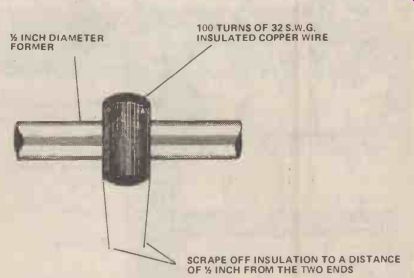
Fig. 4. Details of coil L1, try to keep the coil as neat as possible to
avoid any short circuits.
----------
Parts List
RESISTORS (All 1/4W, 5%)
R1 3K9
R2 47R
POTENTIOMETERS
RV1 RV2
CAPACITORS
C1 C2 ,C3
47K Preset 100K LIN with DPST Switch
10n Mixed Dielectric or Polypropylene 300V AC
100n Polyester
220n Polyester
SEMICONDUCTORS
D1 Diac (Type 133 or similar)
TRI 1 Triac (TRI 400-8 or similar)
MISCELLANEOUS
L1 Coil, 100 turns (see text)
FS1 + Holder
Rocker type switch plate
P.C.B.
Knob to suit
-------------
(adapted from: Hobby Electronics magazine, Sept. 1979)
Also see:
Thyristors: The Great Gate Story