Just in case the R/C modelers have felt neglected in the past few months we've got Bill Berkinshaw, one of the country's leading experts, to review the current radio control scene and some of the technology behind the latest equipment.
CONTROL OVER DISTANT EVENTS and activities has always been a source of fascination to mankind, many early weapons such as sling shots, bows and arrows and even the gun were manifestations of this phenomena. Couple this tendency with another natural trait of model making, or image creating and in psychologists terms radio control modeling is an absolute natural.
For many years the Leonardo da Vincis, Stephensons and Cayleys of this world have produced models to prove inventions, only to have to face the problems of operating them without damage and under a degree of control. Many early experiments in the field of aviation attempted to tether and thus control their creations with varying degrees of success. But thanks to modern electronic techniques a degree of precise controllability from a remote situation undreamt of even 20 years ago, is a reality for anyone with the interest, and to be fair, the finance to embrace it. Not that radio control of models or full size cars, aircraft or boats is anything like that new. My father for instance held a license to operate a spark transmitter for remote control of models in the early 1930's, and full size aircraft such as the D. H. Tiger Moth were flown during WWII under radio control.
---- Many modelers now use support trays to operate their transmitters
in. This transmitter is a four function type --two dual axis control sticks
are fitted.
HOW DOES IT WORK?
A typical radio control system consists of a transmitter, receiver and a number of servos depending on the number of individual items to be operated. Generally the actuation of the controls is by a joystick, either single or dual axis, in the transmitter. Most modern equipment is described as "proportional' that is to say a small control stick movement results in a small servo movement --a large control stick movement a large servo movement etc., the servo moving directly in sympathy with the control stick.
The electronics that make it all happen are not very highly sophisticated as modern electronics go, but nonetheless a great deal of careful design work has to go into the system in order that it should work reliably, be light in weight, and of course not cost too much. No electronic knowledge is necessary to operate radio control, only the ability to read instructions and plug in plugs. Most systems are described as Digital Proportional with encoding and de-coding of the signal largely carried out with computer type ICs. A typical transmitter would comprise of an encoding section where a clock generator e.g., 555 type IC clocks round the various potentiometers coupled to the control sticks. The output from this encoder is then fed, in the form of a chain of pulses of length varying between 1 and 2 mS (milliseconds) plus a larger synchronization pulse, through a mixer stage and the resulting modulated RF signal fed through various filters to the transmitter aerial.
The RF modulation can be of two basic types, Amplitude or Frequency. Many manufacturers are currently changing over from AM to FM systems for as far as Radio Control is concerned the Frequency Modulation systems tend to exhibit better interference rejection characteristics. This is particularly important at present for the high sunspot activity level, and high illegal CB activity level, are combining to make interference a very real problem for 27 MHz radio control operation. Transmitters are all crystal controlled, most have a plug-in crystal facility, the modelers have an agreed list of 'spot' frequencies within the allocated 27 MHz band. Most modern systems will operate quite happily on 25 KHz channel spacing, many of the latest systems will operate on 10 KHz channel spacing.
Normally though 12 spot frequencies only are used ranging from 26.960-27.280 MHz.
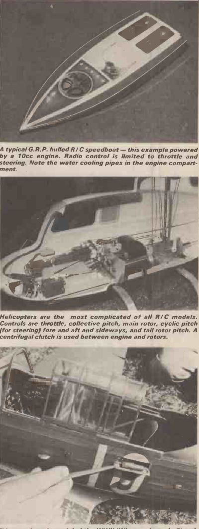
--------- A typical G.R.P. hulled R / C speedboat --this example powered
by a 10 cc engine. Radio control is limited to throttle and steering.
Note the water cooling pipes in the engine compartment.
-----------Helicopters are the most complicated of all R / C models. Controls are throttle, collective pitch, main rotor, cyclic pitch (for steering) fore and aft and sideways, and tail rotor pitch. A centrifugal clutch is used between engine and rotors.
-------This superb scale model of the WWII 'Wirraway' was built and flown by twice National Champion David Vaughan. Note the fire extinguisher and detailed instrument panel --and it flies well too!
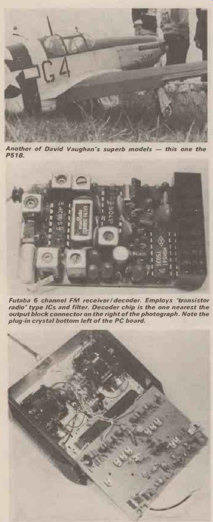
------- Another of David Vaughan's superb models --this one the P51B.
------- Futaba 6 channel FM receiver / decoder. Employs 'transistor radio' type ICs and filter. Decoder chip is the one nearest the output block connector on the right of the photograph. Note the plug-in crystal bottom left of the PC board.
------- Futaba 6 function FM transmitter. Encoding section is a train of half shots' in this case on the section of board nearest the case body. The keen eyed will perhaps spot the varicap diode adjacent to the crystal and the trimmer for adjusting centre frequency. The length of screened cable would normally connect to the aerial and has been removed for photographic purposes.
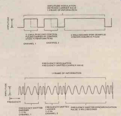
AM OR FM?
The amplitude modulation systems are very simply 'switched carrier wave' transmitters --the carrier-wave being switched on and off in pulses of varying length as dictated by the control stick positions (see Fig. 1) of course for a fair proportion of the time there is no transmission at all and during this time the Automatic Gain Control of the receiver (AGC) tends to open right up and even with correctly damped AGC the receiver is still wide open to any spurious signals around.
An identical means of encoding is used for the Frequency Modulated system but as there is no 'off' time in the data transmission the receiver is at no time 'open' for interference. Modulation is achieved quite simply by employing a capacitatively coupled crystal with a Varicap diode in series, and as the voltage across the varicap is altered the crystal frequency is swung. A deviation of around 1.5 KHz is sufficient and more would not really be desirable as the available bandwidth as specified earlier is only in the order of 10KHz and allowance has to be made for unwanted sideband transmissions when settling on any deviation level as of course sideband deviates just as much as the centre frequency.
Comparatively simple filtering of the RF output is used, mainly concentrating on removing 13.5 MHz (fundamental frequency of crystal) and 54 MHz (second harmonic) components, but care has to be taken in design for the systems are frequently used with mis-matched i.e., retracted aerials etc. for not all modelers, indeed very few are electronics experts.
RECEIVERS
Radio control receivers are comparatively simple, not because sophistication is undesirable, but because use of the equipment in models demands that it be light in weight and small in size. Typical radio control receivers weigh in the region of 1.5 ozs and around 2 in square and ¼-in deep. In common with the transmitter, plug-in crystals for easy channel changing are featured. Design follows conventional superhet procedure with double tuned front end, oscillator mixer stage, IF strip, amplification stage then the decoder. Usually this is of CMOS type as any saving in current consumption is worthwhile, and the very low current levels in CMOS ICs represent a very big saving. Discrete component or even TTL logic decoders are now virtually unheard of; 4000 series CMOS types are the norm.
The decoder outputs are fed to a series of servos, these are electro-mechanical devices which receive pulses in turn from the decoder which are images of the pulses encoded by the transmitter. A reference pulse is produced by the servo amplifier which is compared with the pulse received from the decoder. If a difference, either positive or negative is detected then the servo motor is turned on driving the control surface and a feed back potentiometer until the reference pulse, altered by the feedback potentiometer, and the decoded output pulse are equal, whereupon the servo stops. Information updates are fed to the servos from the decoder at the rate of approximately 30 times per second.
Overall accuracy of the system is highly dependent on servo design, not least on the accuracy of the servo feedback potentiometer where much detailed design work has been done to improve upon the resolution and linearity of the servo. Latest of these developments is the use of 'geared-up' feed back potentiometers as use of a larger portion of pot track tends to minimize the effect of minor deviations in resistance from point to point along the track. Of course, similar problems are present right at the very beginning of the chain, at the control stick itself, where potentiometers are also used. It is fair to say that the majority of failures and problems in radio control equipment occur in the electro-mechanical area rather than the electronic.
POWER
Power for both transmitter and receiver can be either from dry cells (alkaline type preferred) or from re chargeable Nickel Cadium cells. The latter are by far the most suitable as they are able to cope with occasional high current requirements, have greater capacity and can of course be recharged indefinitely. From the economic viewpoint alone Ni-Cads are much to be preferred for if any regular use of the equipment is anticipated, continual replacement costs of dry-cells will soon outweigh the cost of Ni-Cads. Transmitter operating voltage varies from make to make but is usually 9.6 volts sometimes 12 V. (either 8 or 10, 12 V Ni Cads). Receiver/servo voltage is almost universally 4.8 volts (4 x 1.2 volt Ni-Cads). Cell capacity is usually 500mAh (milliamp per hour) providing a system operating time of 3-4 hours.
HOW FAR, HOW HIGH?
IT is fair to say that all modern R/C equipment has more operating range than the normal operator will ever need. The Home Office regulations governing the licensing of R /C transmitters restrict output to a maximum of 1 watt, a level which few transmitters genuinely achieve. This output level is sufficient for the modeler to be able to control his model as far away or as high up as he can see it. It is obvious that if you can't see it, you can't control it, therefore providing the range is sufficient for control of the largest model at the limits of visual range, then all is well; usually about 3/4 mile is the maximum needed.
Range is of course not just dependent on transmitter output but also on receiver sensitivity, which despite the incorporation of good AGC is itself a compromise between overloading at close ranges and lack of sensitivity at extreme ranges. A low output transmitter coupled to a very sensitive and selective receiver is perhaps the optimum but receiver electronics come expensive so the reverse situation is more common place. FM systems do score in this respect as they do not employ AGC instead a limiting device is employed and the receiver is able to be much more sensitive without fear of swamping when operated close to the transmitter.
WHAT CAN BE DONE WITH IT?
Fly, drive, sail or just open your garage door from a distance--there is really no limit to the range of models or devices that can be operated by radio control. Take advantage of the precision and reliability to control superb working replicas of full size aircraft or boats or concentrate on the more sporting side of R/C activities.
All over the country every weekend competitions are held for aircraft boats and cars ranging from the concours D'Elegance type to thrilling racing with high speed models. Most users are however purely interested in the dual relaxations of building and operating models. Few are interested in the technical details of the circuitry of their equipment but simply take advantage of the 'plug it together, switch on and use' aspect. Very few ever attempt any sort of servicing and tuning, particularly those who use the equipment in model aircraft, prefer ring to use the qualified expertise of service agents.
Faults are rare in modern equipment, and if they do occur, are usually as a result of the environment in which the equipment is used. High frequency vibration from high revving two stroke engines, shocks from heavy landings and collisions, moisture from boat use, dirt, are all hazards which the equipment withstands with remarkable reliability. Few uninitiated electronics enthusiasts appreciate the high level of performance that R/C aircraft modelers in particular demand. Most of the models in which the equipment is installed are worth several hundreds of pounds and a momentary malfunction, a click or hiss as heard over a hi-fi loud-speaker can spell total disaster to the R/C aircraft modeler whose model may be flying at less than 10ft above the ground at speeds of up to 150 mph, yet the owner of the equipment will expect 100% reliability for several years of life under the arduous conditions already described.
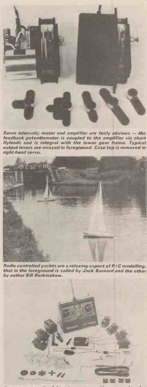
------ Servo internals; motor and amplifier are fairly obvious
--the feedback potentiometer is coupled to the amplifier via short fly-leads
and is integral with the lower gear frame. Typical output levers are
arrayed in foreground. Case top is removed in right-hand servo.
-------- Radio controlled yachts are a relaxing aspect of R/C modeling, that in the foreground is sailed by Jack Barnard and the other by author Bill Berkinshaw.
----- Typical good quality 6 function system with a comprehensive array of accessories including mains voltage charger for receiver and transmitter batteries, alternative capacity receiver batteries and alternative frequency crystal pairs.
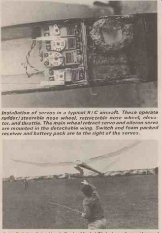
------- Installation of servos in a typical R / C aircraft. These operate
rudder / steerable nose wheel, retractable nose wheel, elevator, and
throttle. The main wheel retract servo and aileron servo are mounted in the
detachable wing. Switch and foam packed receiver and battery pack are to the
right of the servos.
--------John Ralph, of the North Berks Model Club, launches a thermal soaring glider. The model is towed aloft, as are full size gliders by a line, and then after release float around seeking thermal up-currents to extend their duration.
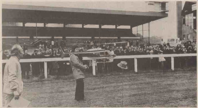
--------V. Nordigen about to lift the hat from a stake with a Jet Ranger
helicopter. Expert pilots can guide models such as this with almost uncanny
precision.
FUNCTIONS
For model control at its simplest 2 function equipment is the usual. Aircraft can be flown, cars driven or boats floated with only a steering control but few modelers use less than 2 controls. A simple aircraft can be operated by a steering control (either a rudder or ailerons on the wing) and elevators. Some modelers use an engine throttle to control height gain or loss. Cars normally do not need more than two controls, steering and combined throttle and brake (a centrifugal clutch is generally employed). Boats use steering and throttle controls. More complicated aircraft can use a basic four function system, elevators, ailerons, rudder and throttle, plus such items as retractable undercarriage, flaps brakes, bomb dropping etc. Servos are either of a rotary type output or linear and are coupled up to the various controls by simple wire pushrods and a variety of commercially available plastic horns, cranks etc.
Operating a model by R /C is not anything like as easy as it appears. It is generally fair to say that if the job is difficult to do directly, that is to say 'sitting in it', then to do it remotely by R /C is doubly difficult. The 'Seat of the pants' feel is removed and that otherwise remarkable instrument the human eye is really not very precise at all when it comes to accurately judging distance or altitudes, particularly when the model can be up to half a mile away. It is fairly safe to attempt to drive a car or boat unaided, provided neither are too fast and space is large enough, but to attempt to fly an R /C aircraft without expert help at hand is almost certain to end in disaster.
The newcomer to R /C flying will almost certainly not only have his own inexperience to hamper him, but also an untried model and a new engine as well. Most hobby dealers are able to introduce prospective R/C modelers to like minded enthusiasts in their area.
BUILD YOUR OWN
Home built R/C equipment only accounts for a very small percentage of that in use, largely because the R/C modeler is interested in the flying, driving or boating more than in the building, and also not many have the confidence in their own ability to risk a valuable model to what in their minds might be equipment of dubious reliability. Their fears are to a certain extent unfounded, for there are excellent kits available and just recently excellent designs published. Electronics Today International have recently published details of an AM system whilst Radio Control Models and Electronics have published an FM system., Both publications are experienced in publishing articles of this type and both are almost guaranteed fool-proof provided the instructions are strictly adhered to. Of course the big attraction is the amount of money to be saved which can be quite, considerable--possibly up to 50%.
Beware of designing your own equipment. I will accept that most people confident enough to embark on a self design project will probably end up with a system that works but at what cost to fellow modelers'. Badly aligned and poorly designed filter networks on transmitters may not affect your model but what of the other users of the R/C frequency allocations? I would suggest that a minimum of test equipment for the home R/C designer would be a spectrum analyzer, digital counter and oscilloscope in order that the transmitter can be adequately checked for sideband emissions.
TRY IT YOURSELF
There are now some 70,000 plus licensed users of Radio Control equipment in 'the UK all participating in a immensely satisfying and creative hobby. There are a host of model clubs in all areas of the country where any would-be members will receive a warm welcome. If you are interested in seeing R/C models in action either visit your local model shops and enquire /look in the yellow pages) or write to one of the national governing bodies for details of nearest local clubs. Do enclose a SAE to those societies though, and don't forget that a license is needed. This can be obtained by anyone--no age limits or test, from the Home Office Radio Regulations Department, Waterloo Bridge House, Waterloo Road, London SE1. The cost is (mult by 1.4 for dollar) £ 2.80 for 5 years so it cannot be described as expensive.
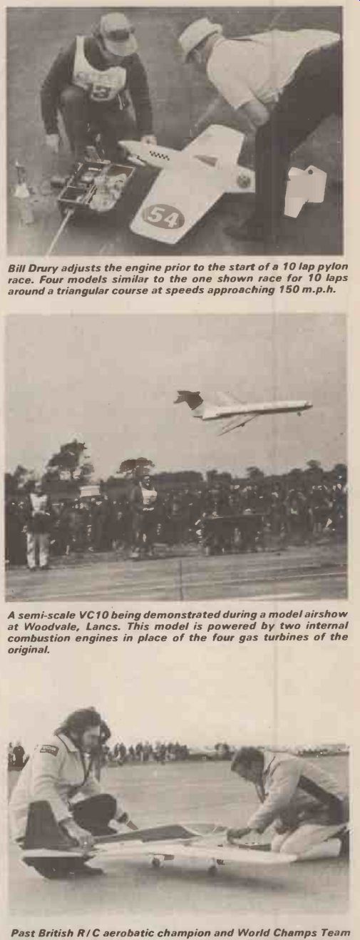
-------- Bill Drury adjusts the engine prior to the start of a 10 lap
pylon race. Four models similar to the one shown race for 10 laps around
a triangular course at speeds approaching 150 m.p.h.
----- A semi-scale VC10 being demonstrated during a model air-show at Woodvale, Lancs. This model is powered by two internal combustion engines in place of the four gas turbines of the original.
----- Past British R/C aerobatic champion and World Champs Team Member Mick Birch starts up the engine in his own design Capricorn model prior to a flight at the British National Champs.
---------
(adapted from: Hobby Electronics magazine, Sept. 1979)
Also see:
Thyristors: The Great Gate Story