Repel insects, upset small furry animals and confuse your cat with HE's Ultraswitch.
INVISIBLE RAYS have always exerted a considerable fascination on man down the ages. Isaac Newton watched apples falling under their influence and Uri Geller bent spoons with them (or did he?) This project falls somewhere between these two extremes of the sublime and the ridiculous. It uses ultrasound; a high frequency sound, well above the range of human hearing to control a relay. By selecting a suitable type you can control your TV, Hi-Fi or bedside light at the touch of a button or as you will see later, with a snap of the fingers.
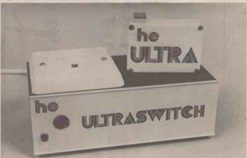
----- Completed units make an attractive and efficient pair.
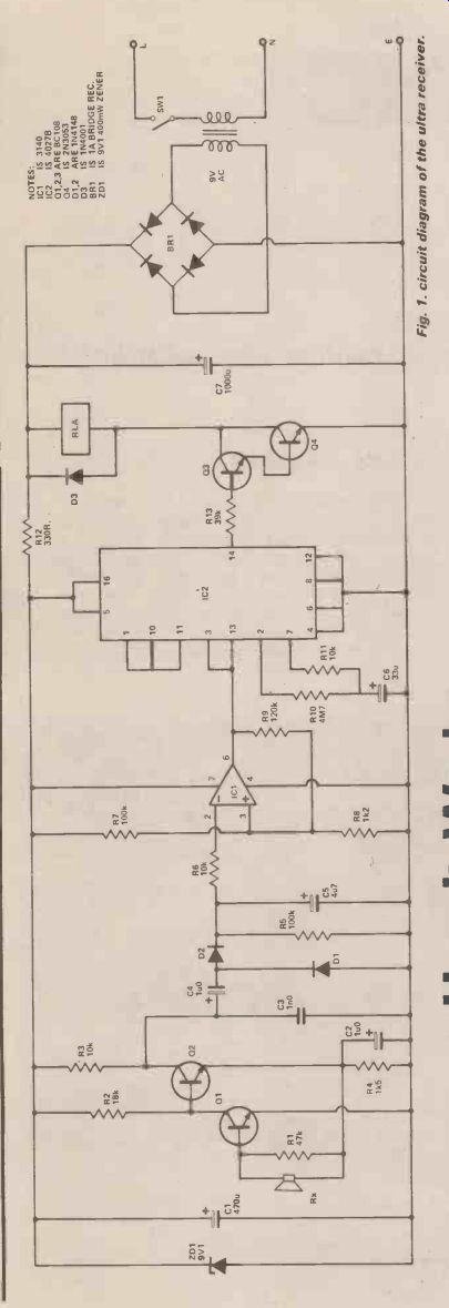
Fig. 1. Circuit diagram of the ultra receiver.
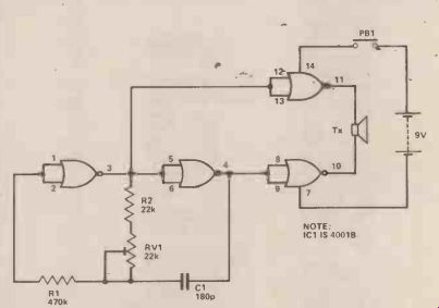
Fig. 2. Circuit diagram of the ultra transmitter.
-------------
How It Works
Transmitter
The transmitter consists of a straightforward CMOS oscillator driving the transducer via two complementary buffer stages. R2 and RV1 together comprise the timing resistance and C1 is the timing capacitor.
Receiver
The ultrasonic signal is amplified by Q1, Q2 a direct coupled amplifier and appears at Q2 collector. C3 is a decoupling capacitor to suppress spurious RF oscillation. The amplified signal charges C5 via C4, D1, D2 and the voltage across C5 is compared with a reference provided by R7, R8 and controls the output of 1C1. R9 provides some positive feedback to produce a degree of hysteresis and speed up the transition time.
The output of IC1 clocks IC2. This is a JK flip-flop whose output toggles, i.e. changes state with each clock pulse. The bistable is disabled for a period determined by R10, C6 to avoid erratic operation. The output of the bistable appears at pin 14 of IC2 and controls super-alpha-pair Q3, Q4 which drive the relay. R12, ZD1 and C11 provide a smooth, stabilized power supply for the amplifier and CMOS circuitry whilst C7 is the main power supply smoothing capacitor.
-----------
-----------
Parts List
-----------
NOISE ANNOYS
The unit is silent in operation. As the ultrasonic carrier beam consists of very high frequency (40 kHz) waves, special transducers have to be used as ordinary microphones and loudspeakers are very inefficient at this frequency. These transducers are just like crystal microphones and earphones except that they are de signed to be resonant, i.e., very sensitive at a particular frequency. The receiver and transmitter units have different characteristics and best results will be obtained if the correct device is used in each application.
They are usually identified with a suffix 'R' for receiver or 'T" for transmitter marked on the case.
Range obtained will depend to an extent on the sensitivity of the particular transducers used but it is also considerably affected by the conditions under which the unit is operated. Ultrasonic waves are quite directional and can be bounced from hard surfaces like walls and, ceilings so that greater range will be achieved in a sparsely furnished room or a corridor and satisfactory operation can often be obtained with the transmitter pointing away from the receiver. Our unit gave a maximum effective range of about twenty feet.
CONSTRUCTION AND USE
Any method of construction may be used although our PCBs are recommended and no special precautions are necessary. However, if you use your unit to control a mains operated device ensure that the mains is kept safely isolated from the control circuitry and use a relay whose contacts are rated for the job.
We mounted our 'Ultraswitch' in an earthed metal case. No special care was taken to protect the transducer from mechanical shock and the unit worked quite reliably.
The transmitter was housed in a small vero-box.
Ensure that the transmitter tuning control is easily accessible. It should be adjusted for maximum range.
There are no other adjustments to make.
Ultrasonic waves are present in many 'natural' sounds and you will find that the switch will operate at varying range in response to jangling keys, crumpling paper and even, at close range, a snap of the fingers. A novel trick is to operate the unit with a handclap.
Remember to use a suitable relay for your application and make all connections safe. Then press that button and turn on.
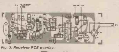
Fig. 3. Receiver PCB overlay.
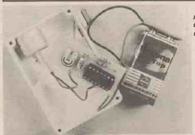
--------Internal view of the ultra transmitter.
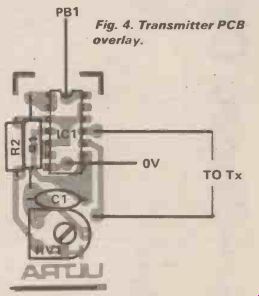
--------Fig. 4. Transmitter PCB overlay.
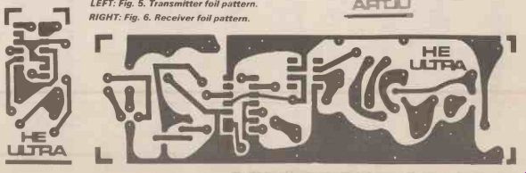
-------LEFT: Fig. 5. Transmitter foil pattern. RIGHT: Fig. 6. Receiver
foil pattern.
---------
Parts List
TRANSMITTER
RESISTORS
R1 R2
RV1 22k min horiz. preset
CAPACITORS
C1 180p polystyrene
SEMICONDUCTORS
IC1 4001B
MISCELLANEOUS
Tx Ultrasonic transmitter transducer. PB1 SPST push-button PCB.
RECEIVER
RESISTORS
R1 R2 R3, 6, 11 R4 R5, 7 R8 R9 R10 (all 1/4W, 5%) 47k 18k 10k 1k5 100k 1k2 120k 4M7
R12 R13
CAPACITORS
330R 39k
C1 C2, 4 C3 C5 C6 C7
SEMICONDUCTORS
IC1 IC2 Q1, 2,3 Q4 D1, 2 D3 BR1 ZD1 470 µ elect.
1 µ tant.
In polystyrene
047 tant.
u 33 tant.
1,000µ elect.
3140 4027B BC108 2N3053 1N4148 1N4001 1A
Bridge Rec.
9V1 400 mW zener
MISCELLANEOUS
Rx Ultrasonic receiver transducer.
Transformer
9V AC 200mA.
SW1 SPST switch. RLA 12V relay to suit.
P.C.B. Mains neon indicator.
Approximate cost (mult by 1.4 for dollar) £ 1 5.
-------------
Buylines
The control circuit for this project was housed in an attractive case (model No. K12) produced by Lektrokit Ltd., Sutton Industrial Park, London Road, Earley, Reading, Berks RG6 1AZ. Tel. (0734) 66916/7.
The Ultrasonic Transducers (type RL400BP) are available from:-Arrow Electronics Ltd., Leader House, Coptfold Road, Brentwood, Essex CM14 4BN.
Price for one pair is (mult by 1.4 for dollar) £4.50 inc. VAT. Postage add 40p.
---------
(adapted from: Hobby Electronics magazine, Sept. 1979)
Also see:
Thyristors: The Great Gate Story