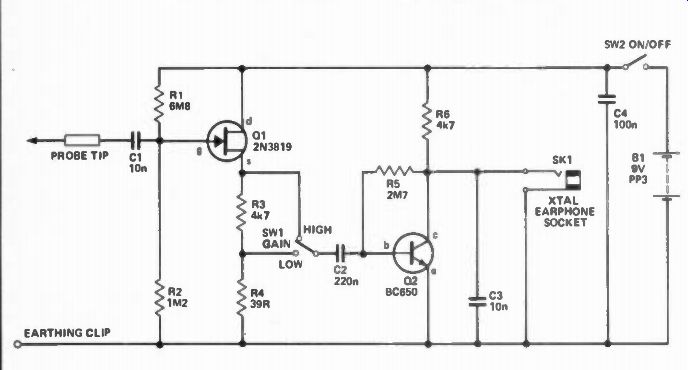
A SIGNAL TRACER for audio work consists of an audio amplifier driving an earphone or loudspeaker, so that small signals can be detected at various points in the circuit. It is a simple refinement, however, to include an AM detector, which will allow signals in the RF (Radio Frequency) and IF (Intermediate Frequency) stages of medium-wave radios to be traced. The circuit shown in Figure 1 is easy to con struct and suitable for audio, RF and IF signal tracing
The circuit is divided into two stages. The first stage uses Q1 as a source follower, providing no voltage gain but a high input impedance (about 1 Megohm) to prevent loading of the circuit being tested. The second stage supplies all the voltage gain (more than 40 dB) by using Q2 in a common emitter configuration. Q2 is biased near to cut-off by R5 and R6, so that it provides a crude form of rectification, as well as gain. Capacitor C3 acts as an RF filter and, in conjunction with the distortion from Q2, produces AM demodulation.
The input signal to Q2 normally comes directly from Q1 via C2, but when a high level input is present, SW1 can be set to the low' position; this avoids overloading by sending the signal through an attenuator network, R3, R4.
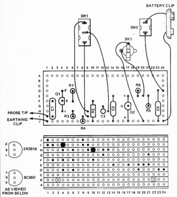
Figure 2 shows the component layout on a piece of Veroboard (24 x 10). The device is housed in a small plastic case, so that it can be hand held, and is connected to the circuit under test via a long M3 bolt (file the tip to a point) with a crocodile clip (on the end of a wire) used for the earth.
The best technique for tracing a signal through a radio is to start at a point, in the signal path, near the first gain stage and work along the signal path towards the output. When you reach a point where the signal 'vanishes' you have roughly located the fault. For example, if there is a signal present at the base of a transistor but not at its collector (or emitter, if it's an emitter follower), then the fault is probably in the transistor or the components around it.
-------------
Parts List
RESISTORS
R1 6M8
R2 1M2
R3,R6 4k7
R4 39R
R5 2M7
CAPACITORS
C1 ,C3 10n polyester
C2 22Cn polyester
C4 100n polyester
SEMICONDUCTORS
Q1 2N3819 FET
Q2 BC650 NPN silicon transistor
-----------------
(adapted from: Hobby Electronics magazine, Apr. 1982)
Also see:
DIY Project--Digital Capacitance Meter
SCALING the Hi-Fi HEIGHTS Part 4