AMAZON multi-meters discounts AMAZON oscilloscope discounts
In this Section, we will examine the various forms of electronic construction. The actual type of construction, of course, depends on the particular piece of equipment. For example, if a project is only in the developmental stage, a technique known as "breadboarding" will be used in its construction. This type of construction permits the easy connection and disconnection of the projected circuit components to help the experimenter determine the proper components for the best circuit performance.
On the other hand, if the correct values of the circuit are known, a more permanent type of construction, such as chassis or etched-circuit is employed.
THE METAL CHASSIS
(A) Chassis and components.
(B) Flat chassis.
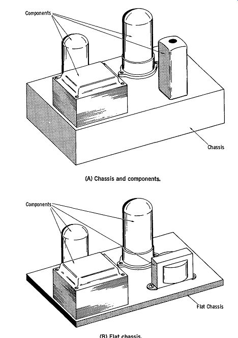
Fig. 1. Metal chassis.
Perhaps the most conventional of all types of electronic construction makes use of the metal chassis. The circuit components-tubes, transformers, potentiometers, etc.-are mounted on the top surfaces of the chassis as shown in Fig. l-J.A. Connections among the various components are made on the underside of the chassis. Sockets are used to make connections to the tube elements.
Metal chassis are available to the home project builder in a number of sizes and shapes. Typical chassis sizes of this particular type range from 4" X 6" X 3" to 13" X 17" X 3". They are available in steel or aluminum (which is much easier to cut and drill with the hand tools commonly found in the home workshop) . A flat chassis is shown in Fig.1-1B.
(A) Pictorial representation of a punch.
Made by Greenlee Tool Co.
(B) Round punch.
Made by Greenlee Tool Co.
(C) Square punch.

Fig. 2. Chassis punches.
Metal Chassis Preparation
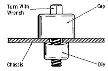
Fig. 3. Operation of a chassis punch.
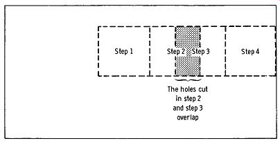
Fig. 4. Successive holes with square chassis punch.
The metal chassis used in commercially produced electronic equipment is machine punched for the required holes for components. This method is not practical for the average home project constructor, but there are inexpensive hand tools that will make the job relatively easy.
For cutting out large holes, such as those required for tube sockets, the simplest approach is to use punches, as shown in Fig. 2. In operation, a hole is first drilled in the chassis. Next, the punch's drive screw is inserted through the hole with its attached cap (see Fig. 3), and the drive screw is tightened with a wrench. This draws the tap up through the chassis, neatly cutting a clean burr-free hole.
There are chassis punches that can cut out round, square, "D", double "D", and keyhole openings. Punch sizes range from ½ inch to 3 inches for the round punches ; ½ inch to 1 inch for the square punches ; 1 1/8 inch to 1 5/8 inch for the "D" punches; 1 1/4 inches to 1 5/8 inches for double "D", and 1 inch to 1 inches for the keynote punches.
The square punch can make either square or rectangular holes. Successive punches are made until the desired hole size is obtained (see Fig. 4). While chassis punches are convenient, they are limited in that a separate punch is required for each hole size.
The circle cutter makes possible the cutting of any desired size hole within its diameter limitation. There are cutters available which will make holes from ½ to 5 inches or more in diameter.
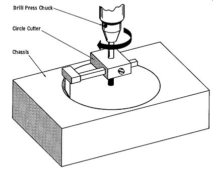
Fig. 5. Operation of a circle cutter.
As shown in Fig. 5, the shank of the cutter is placed in the chuck of a drill press or hand drill (preferably the former). The distance between the pilot drill and cutter is set for one-half the diameter (radius) of the desired hole.
As the cutter is rotated by the drill, the cutting arm rotates, driving the cutting tip gradually through the chassis metal.
Compared to the chassis punch, the circle cutter has the advantage in that it can be easily adjusted to cut more than just one hole size. Smaller chassis holes (½ inch or less) are easily cut with twist drills.
When the circle cutter is used, the hand power drill or drill press should be operated at a relatively low speed 1200 rpm or less. Excessive speed will cause excessive heating, with faster wear of the cutting blade. It is a good idea to lubricate the cutting edge of the blade, perhaps with Vaseline. Finally, be certain that the cutting blade adjusting set screw is securely tightened so that the cutting blade will not loosen and be thrown (due to centrifugal force) when the cutter is turning.
A handy gadget which makes the cutting of odd-size holes in a chassis easy, is a nibbling tool. Fig. 6A is a picture of the nibbling tool, while Fig. 6B illustrates a few of the shapes that the nibbler tool is capable of cutting.
The nibbling tool will cut up to ½ -inch aluminum, copper, or plastic.
(A) Nibbling tool. (B) Nibbling tool cutting capability.
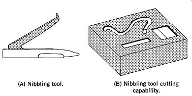
Fig. 6. Nibbling tool and capability.
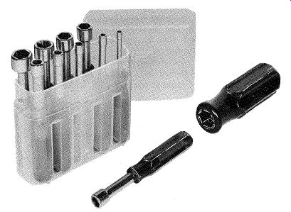
Fig. 7. Nut driver set.
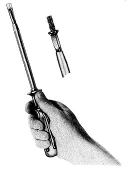
Fig. 8. Screw holding screwdriver.
MISCELLANEOUS TOOLS
Aside from the basic tools described previously, there are a number of tools available which, while not essential, make projects much easier and can save considerable time.
Fig. 7 shows a set of nut drivers that are very handy for tightening nuts in hard-to-reach places where the use of pliers or conventional wrenches is impossible. These nut drivers are available in socket sizes ranging from 3/16 inch to ¾ inch. Color-coding the handles of socket wrenches ac cording to the socket size, makes it easy to select at a glance the desired socket size.
Nut drivers are available in various lengths, including regular, which is 6-inches long; extra long, which is 9 inches in length; and stubby, which is 3¼ inches long.
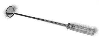
Fig. 9. Inspection mirror.
Screw-holding screwdrivers are invaluable for placing screws in hard-to-reach spots that are too cramped for setting the screw in place by fingers or a pair of pliers.
Fig. 8 shows a typical screw-holding screwdriver.
An inspection mirror (Fig. 9) may be obtained with either a plastic or metal handle, and is a real asset in the inspection of "blind spots," such as the underside of tube socket lugs, terminal strips, etc.
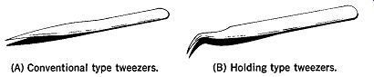
Fig. 10 shows two types of tweezers that can be very helpful in handling
small parts. The tweezers shown in Fig. lOB are of the holding type
that lightly grasp the object. (A) Conventional type tweezers. (B) Holding
type tweezers.
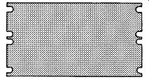
Fig. 11. Relay rack panel.
RACK AND PANEL
This type of construction, which was originated by the telephone companies, is often employed by radio amateurs when they build their gear. Rack and panel construction permits neat vertical "stacking" of a number of electronic subassemblies. The radio amateur finds this type of construction handy for mounting such subassemblies as a speech amplifier, modulator, power supply, driver, and final rf amplifier.
The standard relay rack width is 19 inches. Panel heights range from 1.75 inches to 21 inches. Fig. 11 shows a typical rack panel. Note that the edges of the panel are notched to allow for mounting screws.
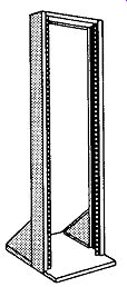
Fig. 12. Open relay rack.
Rack panels are available in either steel or aluminum. Panel thickness may be either 1/8 inch or 3/16. inch.
Fig. 12 shows a typical open relay rack without panels. This type of relay rack is useful when ready access to components is desired.
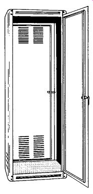
Fig. 13. Enclosed relay rack.
Fig. 13 illustrates an enclosed relay rack, which gives maximum protection to components.
Miscellaneous Enclosures A number of other types of enclosures are available to the constructor. For example, Fig. 14 shows a two-piece enclosure commonly called a "minibox." This is useful for enclosing projects ranging from small preamplifiers to test equipment.
Utility cabinets, such as shown in Fig. 15, are handy for enclosing test equipment, etc.
Amplifier foundations (Fig. 16) are also available.
Note the perforated top which provides adequate ventilation for circuit tubes and components.
Meter cases, such as those in Fig. 17 permit the easy mounting of panel meters. This method of meter housing protects the rather delicate meter movement.
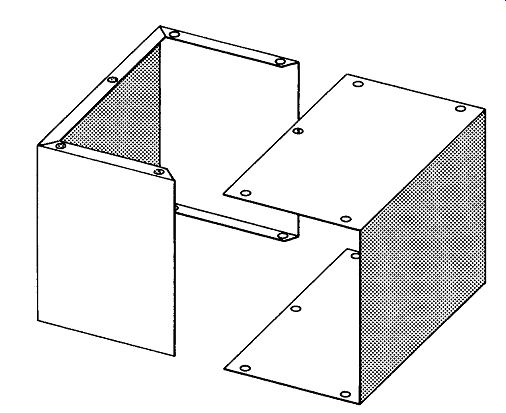
Fig. 14. "Minibox" enclosure.
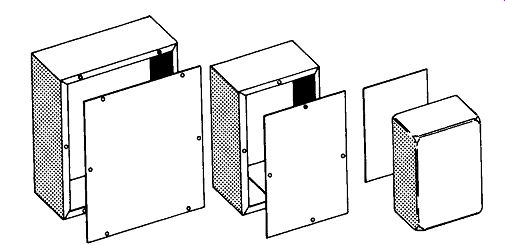
Fig. 15. Utility cabinets.
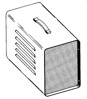
Fig. 18. Portable utility case.
Copper Conductor
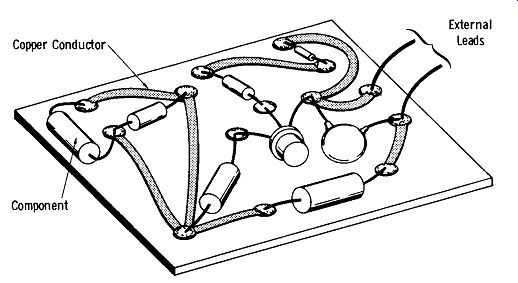
Fig. 19. Etched circuit board.
Portable utility cases (Fig. 18) are useful in constructing portable pieces of electronic test equipment.
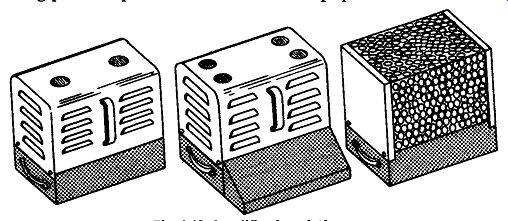
Fig. 16. Amplifier foundations.
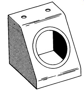
Fig. 17. Meter case.
ETCHED CIRCUITS
This is a relatively new type of electronic construction.
In the etched-circuit technique, copper foil is bonded to one side of a piece of thin insulating material, such as phenolic board or fiberglass. Predetermined portions of the copper foil are etched away, leaving areas of copper that serve as conducting paths between components mounted on the board.
The basic idea of this is shown in Fig. 19.
The etched circuit, sometimes called a "printed circuit," offers several advantages over the more conventional point to-point wiring. First, it is more economical because a large number of printed-circuit boards may be rapidly etched from a master photographic negative. Second, the etched "wiring" can provide more compact circuit packaging than conventional wiring techniques. Etched circuits can often provide greater electrical stability than conventional wiring, particularly where high-frequency circuits are concerned.
The home experimenter can work readily with etched circuits due to the availability of etched-circuit board stock and etching chemicals.
There are two basic approaches that may be used to prepare etched circuits. Perhaps the simplest involves the use of a special masking tape to mark out the portions of the copper that form the circuit "wiring" from the etching solution.
The second method involves a photographic negative which is used in conjunction with a special photosensitive etching-resist chemical. This procedure is somewhat more involved than the tape method and is not too practical for a single etched circuit.
ELECTRONIC CIRCUIT ENCAPSULATION
Circuit encapsulation is a process in which an electronic circuit is encased in an insulating material to completely seal it against the effects of the surrounding environment.
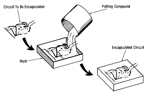
Fig. 20. Encapsulated circuit.
Fig. 20 illustrates the basic idea of circuit encapsulation. The circuit to be encapsulated is placed in a suitable mold. Next, the encapsulating solution is poured into the mold until it completely surrounds the circuit components.
After allowing the encapsulating compound to harden, the complete assembly is removed from the mold. Leads that go to external connections are left outside the encapsulation.
Also see: Basics of Electricity and Electronics with Projects
AMAZON multi-meters discounts AMAZON oscilloscope discounts