AMAZON multi-meters discounts AMAZON oscilloscope discounts
In this Section, we will take a look at the essential tools that you will need to construct electronic equipment; then we will cover those tools which, while not necessarily essential, can make many of the tasks much simpler, easier, and faster.
Also covered in this Section will be the proper procedure for laying out a metal chassis in preparation for drilling and punching. As in any task, knowing the proper procedure will not only make the job much easier; it will result in a finished project that will work well, and of which you will be proud.
THE BASIC TOOL KIT
The basic tools essential in working with electronic equipment are: (a) pliers.
(b) screwdriver.
(c) wire stripper.
( d) soldering iron or gun.
( e) wrenches.
(f) socket punches.
(g) files.
The basic plier group consists of:
(a) electrician's side cutting pliers.
(b) diagonal cutters ("dykes").
(c) long-nose pliers.
(d) tongue and groove pliers.
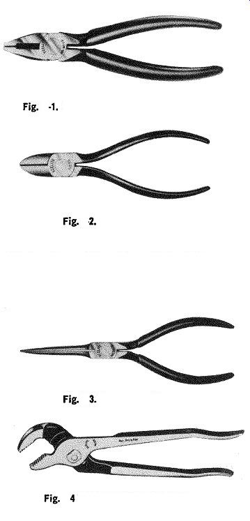
Fig. 1. Electrician's side-cutting pliers.
Fig. 2. Diagonal cutters.
Fig. 3. Long-nose pliers.
Fig. 4 Tongue and groove pliers.
Electrician's side-cutting pliers (Fig. 1) are a general purpose type of pliers that finds a myriad of uses, including holding, tightening, crimping, and cutting. This type of pliers may be used to cut small bolts and machine screws.
Diagonal cutters (Fig. 2) are used to snip hookup wire, component leads, etc., to the proper length. This type of pliers is available in a wide variety of sizes to suit all needs.
When using diagonal cutters, it is important that they not be used as bolt or screw cutters, as this will severely damage both their cutting edges and hinge points.
Long-nose pliers are used to hold small objects and for crimping. As shown in Fig. 3, their construction permits their use in cramped quarters.
Tongue and groove pliers are useful due to their adjust ability to a wide variety of jaw opening sizes. This type of pliers (Fig. 4) is used primarily for tightening joints, bolts, etc.
A good set of screwdrivers is mandatory. The required screwdrivers are:
(a) large standard screwdriver.
(b) small standard screwdriver.
(c) large Phillips head.
(d) small Phillips head.
It is important to use the right screwdriver for each application. For example, do not try to tighten a Phillips head screw with a small standard screwdriver. A screw driver should not be used as a wedge or chisel either. The former will most likely wear the slots in the Phillips-head screw being tightened, and the latter will quickly ruin a good screwdriver blade. It is also important that the proper Phillips-head screwdriver be used for the particular Phillips-head screw. A too large or too small screwdriver will cause excessive screw head wear.
Although it is a relatively minor item, a wire stripper is well worth its small expense. Fig. 5 shows two commonly available types of wire strippers. The one shown in Fig. 5A is an inexpensive type which is adjustable to wire sizes from No. 10 gauge to No. 22 gauge.
The stripper shown in Fig. 5B is a more elaborate version which holds the wire firmly as it is being stripped.
Also, this type of stripper can be adjusted to strip a specific length of insulation from the wire.
(A) Inexpensive wire strippers.
(8) Automatic wire strippers.
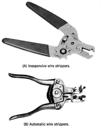
Fig 5. Wire strippers.
Aside from its convenience, a wire stripper prevents nicking of the wire, which often occurs when a knife is used.
Made by Wen Products, Inc.
(A) Soldering gun.
Made by Unger Electric Tools (B) Soldering iron.
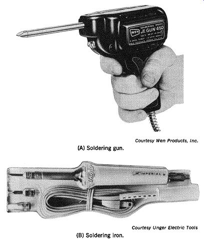
Fig. 6. Soldering gun and soldering iron.
SOLDERING TOOLS
To do an adequate job of electronic circuit wiring, it is important to choose the proper soldering iron or gun. Fig. 6A shows a soldering gun, and Fig. 6B shows a soldering iron.
The decision to use a soldering iron or gun depends on several factors. Because the soldering gun provides rapid heating, it can be used on a job, then promptly tucked away without any danger of a tip retaining heat and causing an unexpected burn or possible fire.
On the other hand, the tip of the soldering gun continues heating as long as its trigger switch is depressed.
This means that it is difficult to obtain precise control over the tip temperature. Also, the tinning on the tip may be burned away if the trigger switch is held down too long.
Due to the danger of excessive tip temperatures, a soldering gun is generally not recommended for use on printed circuit work. An excessive tip temperature can lift the foil from the base. Also, excessive tip temperature can burn the delicate connections found in miniaturized electronic equipment.
Soldering irons are available in a wide range of tip sizes and wattage ratings. As to tip size, the 3/i6-inch designed tip is satisfactory for most electronics wiring. Standard tip sizes range from %-inch to 1 1/4-inch.
Wattage ratings of soldering irons correspond to the tip size-the larger the tip, the higher the wattage rating.
In general, a wattage rating of 60-120 watts is satisfactory for most work. For printed-circuit work, a 30-watt iron is recommended.
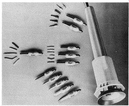
Fig. 7. Soldering iron and replacement tips.
Fig. 7 shows a novel type of soldering iron construction in which the soldering tip and its heating element are separate from the iron handle. This arrangement permits the use of different tip sizes.
Soldering irons are also available which may be operated from a 12-volt battery. This type of iron is useful in the field where there is no other available source of power.
Incidentally, this type of iron is handy for use by the radio amateur in his field trips.
Solders
The type of solder used is as important as the soldering iron or gun. For electrical and electronic work, it is mandatory that a non-acid flux solder be used. Never use acid-core solder.
Nonacid-core solders are available with either natural resin flux or the new synthetic fluxes. Any of these types are satisfactory. Several manufacturers now market "multi core" solders which contain either three or five individual cores of flux. These solders provide easier soldering due to the more ready flow of flux during the operation. Fig. 8 is a sketch of a multicore solder.
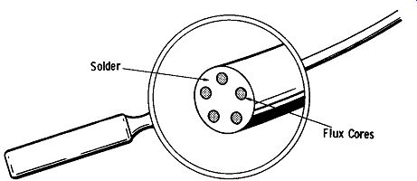
Fig. 8. Multicore solder.
Wire solders are available in a variety of gauges-the most popular ranging from No. 16 to No. 22 gauge.
Soldering Aids
There are several small tools available to assist the soldering operation. Fig. 9 illustrates two of the most popular of these tools. Fig. 9A is a combination tool, which has a pick at one end and a fork at the other end. The pick is useful for removing bits of solder and for cleaning out solder-filled terminals, etc. The forked end is handy for untwisting wires and component leads that may be twisted around a tube socket lug, terminal, etc. The ends of this tool are made of a material to which solder will not adhere.
The second tool (Fig. 9B) is a small metallic brush that is most useful for removing globs of molten solder from heated soldered connections.
The tools described up to this point are the "essentials" for basic electronic assembly work, such as kits, in which all of the mechanical fabrication has been done and all that is required is the actual assembly of components.
Forked End Pick End
(A) Fork and pick.
Metallic Brush
(B) Metallic brush.
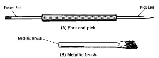
Fig. 9. Soldering aids.
Soldering Tips
Before proceeding further with a description of the various tools, let us take a moment to review some basic soldering techniques.
(A) Cleaning the tip.
(B) Applying solder.
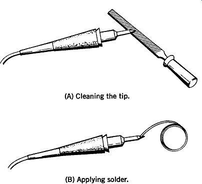
Fig. 10. Tinning a soldering iron.
One of the most important points to remember in soldering is to always keep the soldering iron or gun well tinned. A well-tinned tip is essential for proper heat transfer between the iron tip and the point being soldered. If the tip of the iron or gun is not well tinned, adequate heat transfer will not be obtained, and a poorly soldered connection will most certainly result.
Fig. 10 shows the proper technique in tinning a soldering iron or gun tip. First, the tip is thoroughly cleaned with a piece of fine-grained emery cloth. If the tip is badly pitted, it may be necessary to use a fine-tooth file to remove the pits (see Fig. 10A). The file should be used sparingly so as not to remove an excessive amount of the tip's surface.
NOTE: Some tips are made of materials which must never be filed. Before filing, check the instructions that come with the iron.
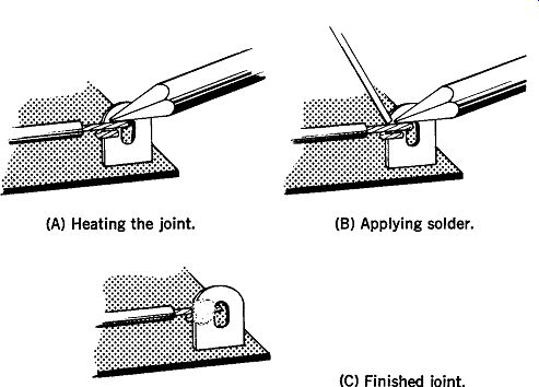
Fig. 11. Proper soldering techniques.
(A) Heating the joint.
(B) Applying solder.
(C) Finished joint.
When the tip is well cleaned, allow the iron or gun to reach operating temperature and apply a light coating of solder, as shown in Fig. lOB. Remove excess solder by wiping the tip lightly with a piece of cloth.
When making a soldered connection, it is important to remember that the solder should never be directly applied to the iron tip. Instead, the joint itself should be heated directly with the tinned iron tip, as shown in Fig. 11A. When the joint has been heated sufficiently, the solder is then applied directly to it, as shown in Fig. llB. When sufficient solder has melted over and covered the joint, the solder is removed first, and then the iron tip is removed from the joint, as shown in Fig. 11C.
(A) Correct solder joint. (B) Incorrect solder joint.
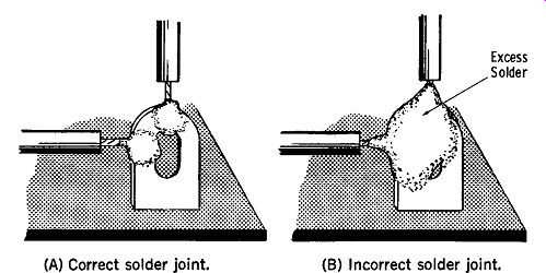
Fig. 12. Correct and incorrect soldering techniques.
Only sufficient solder should be used to cover the actual electrical connection. Fig. 12A shows a satisfactory connection as the solder covers only the actual electrical connection. Fig. 12B is a poor connection, as the solder not only covers the actual electrical connection, but the entire terminal hole. It is important that excess solder not be used, as it is not only wasteful, but can often cause a short circuit by joining to otherwise insulated connections.
Sufficient heat must be applied to the connection so that the solder will flow over the entire electrical connection.
In a properly soldered connection, the solder will "sweat" onto and into the connection. This means that the solder will flow easily, like water, over the connection.
A soldered connection that has not been heated sufficiently will not have the desired "shiny" appearance of a well soldered connection; rather, it will appear grayish and have a grainy texture. Such a joint, known as a "cold" solder joint, possesses poor mechanical strength and will offer a relatively high electrical resistance. (Solder connections, however, should not be relied on for making good mechanical connections. Solder is used to make good electrical connections.) After a soldered connection has been made, and while it is cooling, the leads of the connection should not be moved because any movement will weaken the bond.
SPECIAL ETCHED-CIRCUIT SOLDERING TECHNIQUES
The technique involved in soldering components into, and removing them from, etched-circuit boards varies some what from soldering techniques employed in conventional circuit assembly.
When soldering to etched-circuit boards, a relatively low-temperature solder should be used. Solders with high tin content have this characteristic; therefore, 60-40 (60% tin-40% lead) solder should be used.
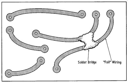
Fig. 13. Solder bridge.
Care must be taken when soldering to an etched circuit board so that the minimum amount of solder consistent with a good electrical connection will be used. Excess solder can cause "solder bridges" between adjacent foil conductors, which can cause short circuits, as shown in Fig. 13. If these solder bridges do occur, they can be removed by carefully heating the solder bridge until it is melted, and then quickly brushing it away with a small wire bristle brush.
Special techniques are employed in desoldering a component from an etched-circuit board. Fig. 14A shows a method that is simple and lessens the chance of damage to the foil due to excessive heat. As shown in Fig. 14A, the leads to the component being replaced are clipped close to the component body, leaving the two leads sticking up from the board. The leads from the replacement component are clipped close to its body as shown in Fig. 14B. The leads of the replacement component are hooked around the leads extending from the board, and soldered in place as shown in Fig. 14C.
(A) Removing defective component.
(B) Preparing new component.
(C) Installing new component.
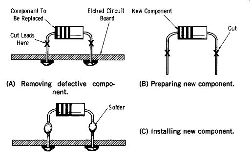
Fig. 14. Method of replacing defective component.
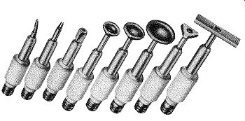
Fig. 15. Desoldering tips.
If the leads connecting the component to the board are too short to use the above technique, the joint where the defective component leads contact the foil should be heated just enough to soften the solder. The component can then be lifted from the board.
When a component has a number of leads connecting it to an etched-circuit board, it is a difficult task to remove it, as all leads must be heated simultaneously. Handy devices to help solve this problem are shown in Fig. 15. Called de soldering tips, they provide a large surfaced, plate-type tip which will simultaneously heat up several component leads at the point where they are soldered to the foil, so that the component can be readily removed.
METALWORKING TOOLS
Since almost all electronic equipment, with the exception of etched circuits, is assembled on a metal chassis, a good understanding of how to prepare a metal chassis for component mounting is essential.
Drills
Mounting holes up to ½-inch are easily made with ordinary twist drills. These drills are available in sets offering drill sizes ranging from 1/16-inch to ½-inch. When selecting a drill set, the old saying "penny wise is pound foolish" certainly applies. An inexpensive set of drills will quickly dull and will have to be replaced after only little use. On the other hand, a quality set of drills will last a long time and will be well worth its initial cost.
An electric hand drill is well worth its cost in terms of saving labor and time.
A drill with a ¼-inch chuck will usually be satisfactory for most work. Although drills with %-inch or ½-inch chucks are available, their increased cost is not warranted.
Twist drills up to ½-inch are now available with ¼-inch shanks so that they will fit drills with ¼-inch chucks.
Power hand drills with built-in solid-state variable-speed controls are now available. In operation, depressing the trigger switch varies the drill speed smoothly from zero to their rated rpm-generally, 1800 rpm. The slow starting speed obtainable with such a drill alleviates the need of using a center punch to form a pilot mark on the chassis.
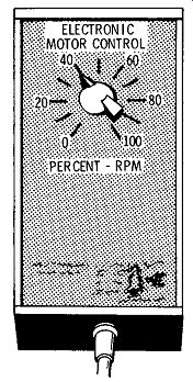
Fig. 16. Variable speed control.
If you already have a hand electric drill, but it is of the constant-speed type, you can obtain an inexpensive solid state speed control, such as shown in Fig. 16, for your brand of drill. Although less convenient than the trigger activated types which are on variable-speed drills, these external speed controls are still very handy.
Also see: Basics of Electricity and Electronics with Projects
AMAZON multi-meters discounts AMAZON oscilloscope discounts