AMAZON multi-meters discounts AMAZON oscilloscope discounts
In this Section, we are going to examine the techniques used in the fabrication of miniature and microminiature electronic circuits. The advent of the transistor made possible the construction of extremely small electronic devices which were not feasible with the more bulky and mechanically fragile vacuum tube. The electronic experimenter can readily obtain miniature electronic components to assemble truly diminutive electronic gear.
MINIATURE ELECTRONIC COMPONENTS
Resistors, capacitors, transformers, and speakers are some of the components available in miniature form, at reasonable cost.
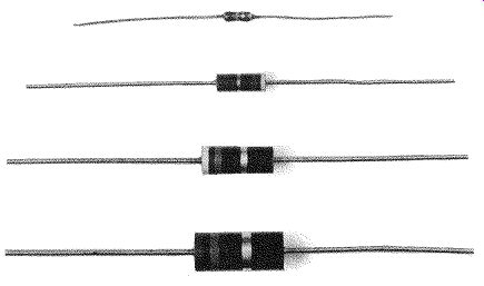
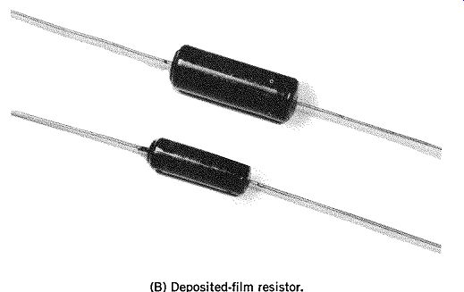
FIG. 1. Miniature resistors. A Carbon-composition resistor. B. Deposited-film
resistor.
Resistors
Resistors suitable for miniature and subminiature circuitry are available in a number of types including carbon composition and deposited metal film. FIG. 1 shows miniature carbon composition and carbon film resistors. The 1/4 watt carbon resistors are commercially available with ohmic values ranging from 0.24 ohm to 22 megohms. Typical metal film resistors are available in ohmic values ranging from 30.1 ohms to 1.5 megohms. Carbon composition resistors are satisfactory in most applications where precise long-term stability is not required. Deposited metal-film resistors offer closer ohmic tolerances and greater stability over long periods of time-at, of course, a higher cost.
Potentiometers
Variable resistors and potentiometers, as well as resistors, are in diminutive sizes.
(A) 1K to 1M potentiometer.
(B) 1K to 500K potentiometer.
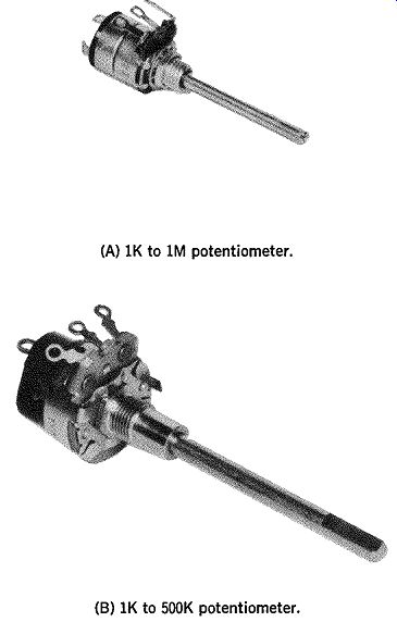
FIG. 2. Miniature carbon-composition potentiometers.
FIG. 2 shows two types of miniature carbon composition potentiometers. The type shown in FIG. 12A is avail able in ohmic values ranging from 1K to 1M. Power dissipation for this type is ½ watt.
The potentiometer shown in FIG. 2B is available in ohmic values ranging from 1000 ohms to 500K. Power dissipation is ½ watt.
Transformers
FIG. 3 shows one type of miniature transformer de signed for the audio frequency portions of transistor circuitry.
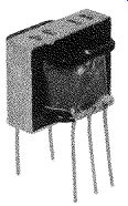
FIG. 3. Subminiature audio transformer.
These transformers are available with a wide range of characteristics. Typical of these are audio input, audio coupling, audio drive, and audio output. Impedance values range from 30k ohms for audio input and interstage transformers to 1k ohms to 4 ohms for drive and output transformers.
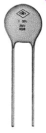
FIG. 4. Miniature high capacitance capacitor.
Capacitors
FIG. 4 shows a typical disc-ceramic capacitor that is commercially available for miniaturized transistor equipment. These capacitors are available in a wide range of capacitances, voltage ratings, tolerances, and temperature coefficients.
Made by Mallory Capacitor Co., Div., P. R. Mallory & Co., Inc.
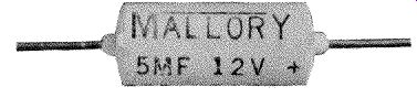
FIG. 5. Miniature tubular electrolytic capacitor.
FIG. 5 illustrates a miniature electrolytic capacitor suitable for miniature
circuitry. Capacitance values usually range from 1 µ,F to 200 µ,F with
voltage ratings of between 3 and 150 volts.
RF Chokes (Radio-Frequency Chokes)
FIG. 6 shows an rf choke which is suitable for use in miniaturized equipment.
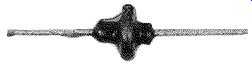
FIG. 6. Miniature rf choke.
The small size of these rf chokes is made possible by placing their windings on ferrite cores which greatly increase their inductance for a given number of turns.
Miniature Speakers
FIG. 7 shows a speaker suitable for use in miniature receivers, amplifiers, etc. The diameter of the cone is only 1½ inches.
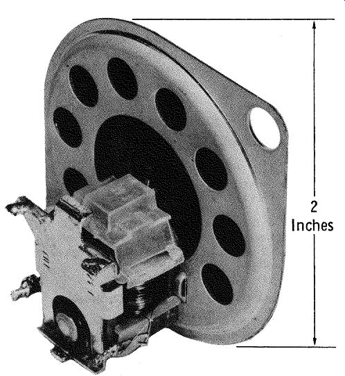
FIG. 7. Miniature speaker.
Miniature 1-F Transformers
FIG. 8 shows one miniature i-f (intermediate-frequency) transformer. These transformers are suitable for use in miniaturized receivers.
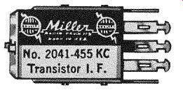
FIG. 8. Miniature i-f transformer.
(B) Schematic representation.
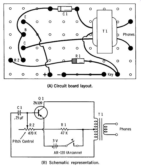
Fig 9. Miniature code oscillator.
PHENOLIC PERFORATED BOARD AS CHASSIS FOR MINIATURE PROJECTS
One of the simplest methods of miniature project construction is shown in FIG. 9. A piece of perforated phenolic board, just large enough to contain the project components, is used. The components are arranged as closely as possible to each other, with eyelets being used as the electrical and mechanical tie points ("flea clips" can also be used). The project shown in FIG. 9A is a miniature code practice oscillator. The schematic diagram of the oscillator is shown in FIG. 9B. Phenolic perforated board makes an ideal chassis for miniature circuits as it can be easily cut to any desired shape, and its evenly spaced holes make component layout easy.
Perforated Phenolic Board Transistor Component
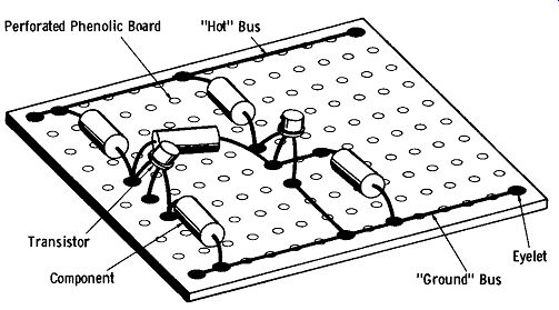
FIG. 10. Practical component layout.
FIG. 10 shows a method of component layout on perforated board which provides a logical compact arrangement for easy assembly and testing of the completed unit. As shown in FIG. 10, a length of heavy (No. 14 or No. 16) base copper wire is run along opposite sides of the board.
One of these serves as a "common" or ground bus to which all circuit grounds are tied. All + or - supply voltage points in the circuit are connected to the other wire. Transistors are mounted midway between the two buses as shown, with circuit elements, such as emitter-bias resistors, collector-lead resistors, etc. being connected between their respective transistor terminals and the appropriate bus.
FIG. 11. Stacked perforated board.
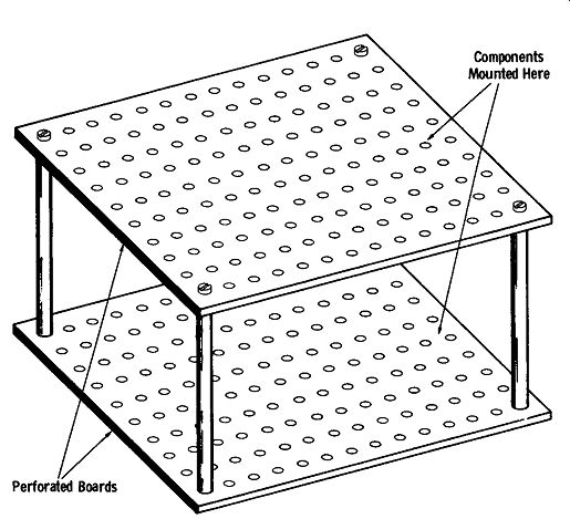
Stacked Perforated Board Miniature Assemblies
FIG. 11 shows an arrangement where individual perforated board miniature assemblies are stacked-one above the other. This permits an even greater component density, and is particularly adaptable when several circuit sub-assemblies--one on each wafer-are combined to form a complete circuit.
The individual perforated board wafers are separated by a length of bus wire placed through a hole in each corner of the boards, and secured in place with a drop of epoxy cement.
ENCAPSULATING MINIATURE CIRCUITS
It is often desirable to encapsulate a finished piece of miniaturized electronic equipment to offer protection from the surrounding environment as well as often adding to its appearance.
FIG. 12 shows a simple method of encapsulating a miniature electronic circuit. The circuit is placed in a container, such as a small plastic box, which is slightly larger than the circuit being encapsulated (FIG. 12A).
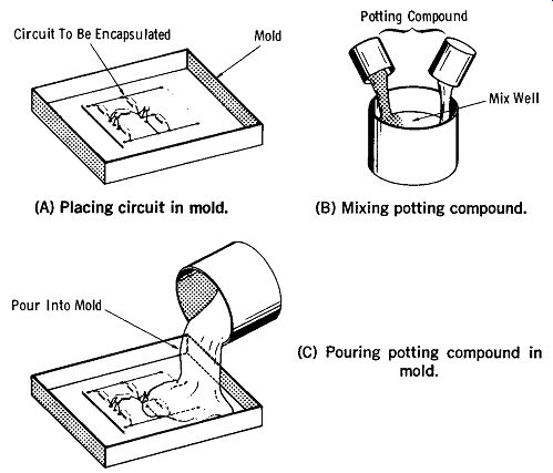
FIG. 12. Encapsulating a miniature circuit. (A) Placing circuit in mold.
(B) Mixing potting compound. (C) Pouring potting compound in mold.
Next, the encapsulating compound is prepared. A suit able compound for this purpose is Silastic RTV, manufactured by the Dow Corning Corp. This compound comes in two parts which are mixed together prior to pouring into the mold. When mixing the parts be sure that they are thoroughly blended (FIG. 12B). Pour the mixture slowly into the mold so as not to form air bubbles. See FIG. 12C. Dow Corning manufactures several variations of the basic Silastic. One type will cure in approximately 30 minutes, while the other takes at least 24 hours to fully cure.
When the Silastic has thoroughly cured, the encapsulated assembly can be easily removed from its mold.
If a more rigid encapsulation is required, the circuit can be encapsulated in an epoxy compound. As in the case of the Silastic compound mentioned previously, most epoxys come in two parts, the epoxy resin and the catalyst. These two are mixed together and poured into a mold in which the circuit assembly has been placed.
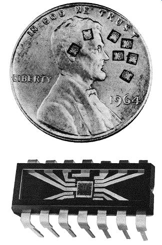
FIG. 13. Typical integrated circuits.
MICROMINIATURIZATION
During the last several years, the big word in the electronics industry has been integrated circuits. These devices offer what is perhaps the ultimate in microminiaturization.
An integrated circuit basically consists of a number of individual active semiconductors, such as diodes and transistors, found on and within a single chip of semiconductor material, such as silicon. FIG. 13 shows the basic idea of an integrated circuit.
Since integrated circuits contain a number of transistors and their related components, it is easy to conceive that a complete radio receiver can be produced in a small chip about half the size of a postage stamp. (Of course, this does not include the antennas, tuning and volume control, or loudspeaker.) Since computers contain many thousands of transistors, diodes and related components, integrated circuits (originally designed for use in electronic computers) provide a great reduction in overall computer size.
Integrated circuits have more recently become available as linear circuit elements. Linear integrated circuits may be used as amplifiers, both audio-frequency and radio-frequency, and as a result, are finding their way into industrial and consumer products.
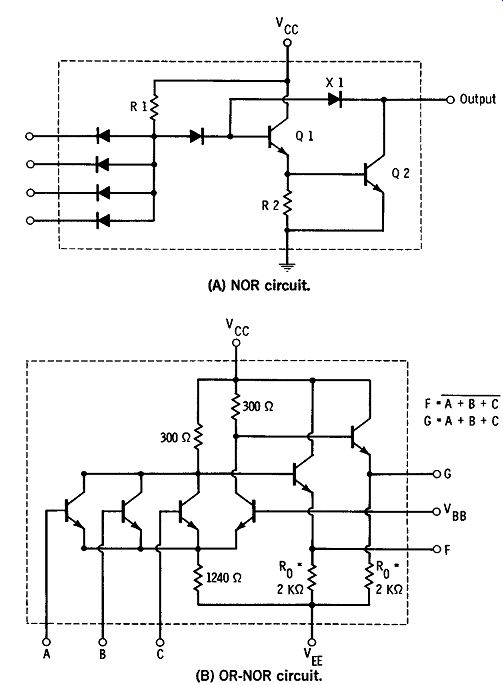
FIG. 14. Schematic of typical integrated circuits. (A) NOR circuit. (B)
OR-NOR circuit.
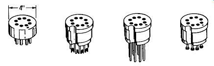
FIG. 15. Sockets for integrated circuits.
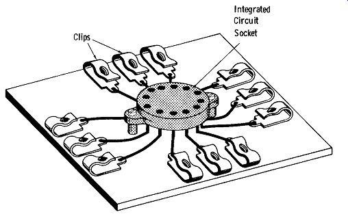
FIG. 16. Mounting integrated circuit socket for experimental use.
EXPERIMENTING WITH INTEGRATED CIRCUITS
Due to volume production, linear integrated circuits are now available to the experimenter at low cost. These inexpensive integrated circuits are available in several different physical configurations and lead arrangements, depending on the type and manufacturer. FIG. 14 shows two types of integrated circuit configurations.
Due to the close spacing of integrated circuit leads, care must be taken when soldering them into a circuit to avoid short circuits between leads. FIG. 15 shows a socket de signed especially for integrated circuits. The use of this socket makes it easy to attach leads to the integrated circuit terminals. It is also easy to substitute different integrated circuits in the socket to check performance.
FIG. 16 shows a handy setup which simplifies experimenting with integrated circuits. The leads which are attached to the integrated-circuit socket terminals are connected to Fahnestock clips for easy connection to other parts of the experimental project. The socket is secured to a small piece of wood, plastic, or other insulating material with epoxy cement.
When working with integrated circuits, it should be kept in mind that they are, with a few exceptions, very low power devices. As a result, be sure to check the maximum ratings of the integrated circuit carefully before using it.
Also see: Basics of Electricity and Electronics with Projects
AMAZON multi-meters discounts AMAZON oscilloscope discounts