AMAZON multi-meters discounts AMAZON oscilloscope discounts
The majority of hobby semiconductor projects use relatively low-power transistors. Since these transistors are equipped with wire leads, the simplest way of connecting them into the circuit is by simply soldering their leads directly into the circuit. When doing this, there are several precautions that should be observed. First, the leads to the transistor should be kept as long as possible, to minimize the heat that is conducted into the transistor when it is being soldered into place. Under no circumstances should the leads be cut shorter than %-inch from the body of the transistor.
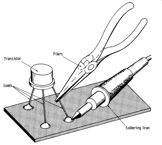
FIG. 1. Using pliers as a heat sink.
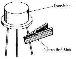
FIG. 2. Clip-on lead heat sink.
WORKING WITH TRANSISTORS
When soldering a transistor into the circuit, it is a good idea to grasp the lead being soldered with a pair of fine-nose pliers as shown in FIG. 1. The pliers act as a heat sink, conducting heat away from the transistor.
FIG. 2 shows a clip-on heat sink that can be used in place of a pair of pliers. Resembling an alligator clip with flat jaws, the heat sink is clipped to the lead being soldered, thus leaving the hands free to work.
When handling any semiconductor device, keep in mind that, while they are quite rugged mechanically, they can be damaged easily if they are dropped.
Semiconductor leads should not be flexed unnecessarily because they can break off. By the same token, when bending a semiconductor's lead, do not make the bend closer than ¼-inch from the point where the leads enter the body of the semiconductor. Otherwise, the seal where the lead enters the semiconductor may be broken, leading to early failure of the semiconductor.
If a number of different transistor types are to be checked for performance, the use of transistor sockets is highly recommended; thus, the resistor leads will not be subjected to continual heating and flexing during the soldering operation.
(A) Socket secured with spring nut.
(B) Socket held with two small screws.
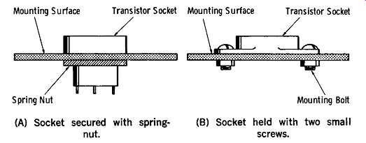
FIG. 3. Methods of mounting small transistor socket.
FIG. 3 illustrates how two of the more common sockets for small transistors are mounted. The socket type shown in FIG. 3A is mounted by passing the socket through a hole and securing it in place with a spring-nut.
The socket shown in FIG. 3B is mounted in a similar manner, with the exception that it is held in place by two small screws.
POWER TRANSISTOR MOUNTING
It is common practice to insert power transistors into sockets, since they are usually too heavy to be sturdily supported by their leads, and it is generally necessary to place the body of a power transistor against a metallic surface which will act as a heat sink.
FIG. 4 shows a common method of mounting a power transistor. Note the use of the mica insulating washer placed between the body of the transistor and heat sink.
This is necessary since the collector of the transistor is internally connected to the transistor case, and thus, the case of the transistor must be insulated from the heat sink (which is generally at ground potential) to avoid a short circuit between the transistor collector and the heat sink.

Fig. 4. Method of power transistor mounting.
In cases where the transistor collector is at the same potential as the heat sink, the insulating washer may, of course, be omitted.
Heat Sinks
When a transistor has a collector dissipation rating of over 500 mW, a heat sink is usually required. Power transistors are designed so that they may easily be attached to a metal plate or chassis of the equipment in which they are used. This relatively large metal surface then serves as the heat sink.
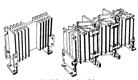
FIG. 5. Transistor heat sinks.
FIG. 5 shows two types of heat sinks which are commercially available. Note the fins that efficiently radiate heat absorbed from the transistor. These heat sinks may be purchased with holes already drilled for the acceptance of the more common types of power transistors.
When mounting a power transistor on a heat sink, it is a good idea to spread a thin layer of silicone grease on the area of the transistor where it touches the heat sink.
This grease, which may be purchased especially for this purpose, aids in the transfer of heat from the transistor to the heat sink.
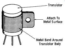
FIG.
6. Small transistor heat sink.Attach To Metal Surface, Metal
Band Around Transistor Body
FIG. 6 shows a method of providing a heat sink for lower-power (250-500 milliwatt) transistors. A band of aluminum is fashioned to fit around the case of the transistor.
The tab is then bolted to the metal chassis or other heat sink. Since the collectors of most of these small transistors are isolated from the case, no insulation is needed between the transistor case and band.
Also see: Basics of Electricity and Electronics with Projects
AMAZON multi-meters discounts AMAZON oscilloscope discounts