The only contact most users of audio equipment will have with digital signal processing (DSP) techniques is likely to be when they play a compact disc - the ubiquitous 'CD' - though there are a number of other 'digital' procedures in widespread use, such as in the transmission and decoding of FM stereo broadcasts, quite apart from the manufacture of CDs and other recordings, and it’s probable that even more will be introduced in the next few years.
However, this is a very large field, which could not be covered adequately in a single SECTION, so I propose to consider in detail only those techniques used in the initial encoding and subsequent replay of CDs, on the grounds that the basic electronic techniques used for this purpose have enough in common with those employed ( For example in digital tape recording with both fixed head and rotary head machines) that an explanation of how the CD system works should also help to throw light on other similar processes.
WHY USE DIGITAL TECHNIQUES?
In the past fifty years, the equipment and technology needed for the production of high quality 'analog' tape recordings (by which I mean recordings of signals which exist in 'real time' and are continuously variable) by way of multi-track, reel-to-reel machines, usually operating at a tape speed of 38.1 cms/s (15 in./s) has reached a very high standard of quality, and one might reasonably wonder why it should be thought necessary to seek to improve on this.
However, in practice, although the first-generation 'master tape' produced from a recording session using such a machine may be of superb technical quality, this will inevitably contain recording or performance faults which will require editing, and this edited master tape must then be copied - most probably twice or more times - in order to get a tidy version of the original. For security of the original recording, further working copies must then be made before the production of say, a number of vinyl discs, or compact cassettes, can begin.
Unfortunately, each time a successive analogue tape copy is made, some degradation of the original signal will occur, in respect of bandwidth and signal-to-noise ratio, and as a result of minor tape malfunctions and 'dropouts'. So by the time the recording has been converted into a cassette tape, or an undulating groove on the surface of a vinyl disc, a lot of the immediacy and transparency of the original recording will have been lost.
By comparison with this, a 'digital' recording - in which the analogue signal has been converted into a 'digitally encoded' electronic equivalent where the continuously variable voltage levels of the original signal are represented by a repetitively sampled sequence of alternating 0s and 1s , which signify clearly defined, constant and distinct electrical voltage levels --is , at least in principle, capable of being copied over and over again, without any degradation at all. Any minor errors in the received 0 or 1 levels can be automatically corrected, and freed from any spurious noise -- a process which is obviously impracticable with any signal in analogue form.
In addition, the incoming signal, once converted into its digital form, need no longer exist in any specific time domain. After all, it’s now just a collection of data, divided into a sequence of blocks. This allows the data to be divided, stored and manipulated, and reassembled in any way necessary for the purposes of recording or handling. It also means that, once the signal is converted into digital form, it’s intrinsically free from any added 'rumble', 'wow' or 'flutter' or other intrusions due to the speed irregularities of the subsequent recording or replay systems. However, there are also snags.
PROBLEMS WITH DIGITAL ENCODING
Quantization noise:
Although a number of ways exist by which an analogue signal can be converted into its digital equivalent, the most popular, and the technique used in the CD, is the one known as 'pulse code modulation', usually referred to as 'PCM'. In this, the incoming signal is sampled at a sufficiently high repetition rate to permit the desired audio bandwidth to be achieved. In practice this demands a sampling frequency somewhat greater than twice the required maximum audio frequency. The measured signal voltage level, at the instant of sampling, is then represented numerically as its nearest equivalent value in binary coded form (a process which is known as 'quantization'). This has the effect of converting the original analogue signal, after encoding and subsequent decoding, into a voltage 'staircase' of the kind shown in FIG. 1. Obviously, the larger the number of voltage steps in which the analogue signal can be stored in digital form (that shown in the figure is encoded at '4-bit' – 24 or 16 possible voltage levels), the smaller each of these steps will be, and the more closely the digitally encoded waveform will approach the smooth curve of the incoming signal.
The difference between the staircase shape of the digital version and the original analogue waveform causes a defect of the kind shown in FIG. 2, known as 'quantization error', and since this error voltage is not directly related in frequency or amplitude to the input signal it has many of the characteristics of noise, and is therefore also known as 'quantization noise'. This error increases in size as the number of encoding levels is reduced. It will be audible if large enough, and is the first problem with digitally encoded signals. I will consider this defect, and the ways by which it can be minimized, later in this SECTION.
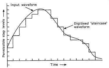
FIG. 1 Digitally encoded/decoded waveform. Digitized 'staircase' waveform
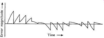
FIG. 2 Quantization error.
Bandwidth
The second practical problem is that of the bandwidth which is necessary to store or transmit such a digitally encoded signal. In the case of the CD, the specified audio bandwidth is 20 Hz to 20 kHz, which requires a sampling frequency somewhat greater than 40 kHz. In practice, a sampling frequency of 44.1 kHz is used. In order to reduce the extent of the staircase waveform quantization error, a 16-bit sampling resolution is used in the recording of the CD, equivalent to 216 or 65536 possible voltage steps. If 16 bits are to be transmitted in each sampling interval, then , for a stereo signal, the required bandwidth will be 2 X 16 X 44100 Hz, or 1.4112 mHz, which is already seventy times greater than the audio bandwidth of the incoming signal. However, in practice, additional digital 'bits' will be added to this signal for error correction and other purposes, which will extend the required bandwidth even further.
Translation non-linearity The conversion of an analogue signal both into and from its binary coded digital equivalent carries with it the problem of ensuring that the magnitudes of the binary voltage steps are defined with adequate precision. If , for example, '16-bit' encoding is used, the size of the 'most significant bit' (MSB) will be 32768 times the size of the 'least significant bit' (LSB). If it’s required that the error in defining the LSB shall be not worse than ±0.5%, then the accuracy demanded of the MSB must be at least within ±0.0000152% if the overall linearity of the system is not to be degraded.
The design of any switched resistor network , for encoding or decoding purposes, which demanded such a high degree of component precision would be prohibitively expensive, and would suffer from great problems as a result of component ageing or thermal drift. Fortunately, techniques are available which lessen the difficulty in achieving the required accuracy in the quantization steps. The latest technique, known as 'low bit' or 'bit-stream' decoding, side-steps the problem entirely by effectively using a time-division method, since it’s easier to achieve the required precision in time, rather than in voltage or current, intervals.
Detection and correction of transmission errors
The very high bandwidths which are needed to handle or record PCM encoded signals means that the recorded data representing the signal must be very densely packed. This leads to the problem that any small blemish on the surface of the CD, such as a speck of dust, or a scratch, or a thumb print could blot out, or corrupt, a significant part of the information needed to reconstruct the original signal. Because of this, the real-life practicability of all digital record/replay systems will depend on the effectiveness of electronic techniques for the detection, correction or, if the worst comes to the worst, masking of the resultant errors. Some very sophisticated systems have been devised, which will also be examined later.
Filtering for bandwidth limitation and signal recovery
When an analogue signal is sampled, and converted into its PCM encoded digital equivalent, a spectrum of additional signals is created, of the kind shown in FIG. 3(a), where/s is the sampling frequency and/m is the upper modulation frequency. Because of the way in which the sampling process operates, it’s not possible to distinguish between a signal having a frequency which is somewhat lower than half the sampling frequency and one which is the same distance above it; a problem which is called 'aliasing'. In order to avoid this, it’s essential to limit the bandwidth of the incoming signal to ensure that it contains no components above f_s/2.
If, as is the case with the CD, the sampling frequency is 44.1 kHz, and the required audio bandwidth is 20 Hz to 20 kHz, +0/-1 dB, an input 'anti-aliasing' filter must be employed to avoid this problem. This filter must allow a signal magnitude which is close to 100% at 20 kHz, but nearly zero (in practice, usually -60 dB) at frequencies above 22.05 kHz. It’s possible to design a steep-cut, low-pass filter which approximates closely to this characteristic using standard linear circuit techniques, but the phase shift, and group delay (the extent to which signals falling within the affected band will be delayed in respect of lower frequency signals) introduced by this filter would be too large for good audio quality or stereo image presentation.
This difficulty is illustrated by the graph of FIG. 4, which shows the relative group delay and phase shift introduced by a conventional low-pass analogue filter circuit of the kind shown in FIG. 5. The circuit shown gives only a modest -9 0 dB/octave attenuation rate, while the actual slope necessary for the required anti-aliasing characteristics (say, 0 dB at 20 kHz and -60 dB at 22.05 kHz) would be -426 dB/octave. If a group of filters of the kind shown in FIG. 5 were connected in series to increase the attenuation rate from -9 0 dB to -426 dB/octave, this would cause a group delay, at 20 kHz, of about 1 ms with respect to 1 kHz, and a relative phase shift of some 3000°, which would be clearly audible.*
*In the recording equipment it’s possible to employ steep-cut filter systems in which the phase and group delay characteristics are more carefully controlled than would be practicable in a mass-produced CD replay system where both size and cost must be considered.
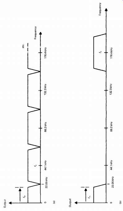
FIG. 3 PCM frequency spectrum (a) when sampled at 44.1 kHz and (b) when
four times oversampled.
Similarly, since the frequency spectrum produced by a PCM encoded 20 kHz bandwidth audio signal will look like that shown in FIG. 3(a), it’s necessary, on replay, to introduce yet another equally steep-cut low-pass filter to prevent the generation of spurious audio signals which would result from the heterodyning of signals equally disposed on either side of f_s/2.
An improved performance in respect both of relative phase error and of group delay in such 'brick wall' filters can be obtained using so-called 'digital' filters, particularly when combined with pre-filtering phase correction. However, this problem was only fully solved, and then only on replay (because of the limitations imposed by the original Philips CD patents), by the use of 'over-sampling' techniques, in which , for example, the sampling frequency is increased to 176.4 kHz ('four times over sampling'), which moves the aliasing frequency from 22.05 kHz up to 154.35 kHz, giving the spectral distribution shown in FIG. 3(b). It’s then a relatively easy matter to design a filter, such as that shown in FIG. 14, having good phase and group delay characteristics, which has a transmission near to 100% at all frequencies up to 20 kHz, but near zero at 154.35 kHz.
THE RECORD-REPLAY SYSTEM
The recording system layout
How the signal is handled, on its way from the microphone or other signal source to the final CD, is shown in the block diagram of FIG. 6. Assuming the signal has by now been reduced to a basic L-R stereo pair, this is amplitude limited to ensure that no signals greater than the possible encoding amplitude limit are passed on to the analogue-to-digital converter (ADC) stage. These input limiter stages are normally cross linked in operation to avoid disturbance of the stereo image position if the maximum permitted signal level is exceeded, and the channel gain reduced in consequence of this, in only a single channel.
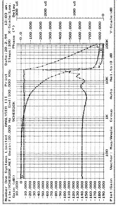
FIG. 4
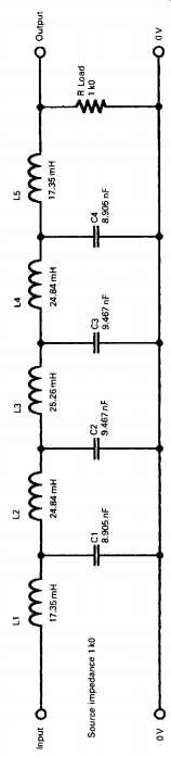
FIG. 5 Steep-cut LP filter circuit.
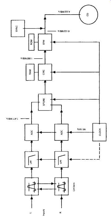
FIG. 6 Basic CD recording system.
The signal is then passed to a very steep-cut 20 kHz anti-aliasing filter (often called a 'brick wall filter') to limit the bandwidth offered for encoding. This bandwidth limitation is a specific requirement of the digital encoding/decoding process , for the reasons already considered. It’s necessary to carry out this filtering process after the amplitude limiting stage, because it’s possible that the action of peak clipping may generate additional high frequency signal components. This would occur because 'squaring-off the peaks of waveforms will generate a Fourier series of higher frequency harmonic components.
The audio signal, which is still, at this stage, in analogue form, is then passed to two parallel operating 16-bit ADCs, and, having now been converted into a digital data stream, is fed into a temporary data-storage device - usually a 'shift register' - from which the output data stream is drawn as a sequence of 8-bit blocks, with the 'L' and 'R' channel data now arranged in a consecutive but interlaced time sequence.
From the point in the chain at which the signal is converted into digitally encoded blocks of data, at a precisely controlled 'clock' frequency, to the final transformation of the encoded data back into analogue form, the signal is immune to frequency or pitch errors as a result of motor speed variations in the disc recording or replay process.
The next stage in the process is the addition of data for error correction purposes. Because of the very high packing density of the digital data on the disc, it’s very likely that the recovered data will have been corrupted to some extent by impulse noise or blemishes, such as dust, scratches, or thumb prints on the surface of the disc, and it’s necessary to include additional information in the data code to allow any erroneous data to be corrected. A number of techniques have been evolved for this purpose, but the one used in the CD is known as the 'Cross-interleave Reed-Solomon code' or CIRC. This is a very powerful error correction method, and allows complete correction of faulty data arising from quite large disc surface blemishes.
Because all possible 0 or 1 combinations may occur in the 8-bit encoded words, and some of these would offer bit sequences which were rich in consecutive 0s or 1s , which could embarrass the disc speed or spot and track location servo-mechanisms, or, by inconvenient juxtaposition, make it more difficult to read the pit sequence recorded on the disc surface, a bit-pattern transformation stage known as the 'eight to fourteen modulation' (EFM) converter is interposed between the output of the error correction (CIRC) block and the final recording. This expands the recorded bit sequence into the form shown in FIG. 7, to facilitate the operation of the recording and replay process. I shall explain the functions and method of operation of all these various stages in more detail later in this SECTION.
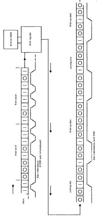
FIG. 7 The EFM process. Disc indentations (if EFM was not employed) Disc
indentations (with EFM)
Disc recording
This follows a process similar to that used in the manufacture of vinyl EP and LP records, except that the recording head is caused to generate a spiral pattern of pits in an optically flat glass plate, rather than a spiral groove in a metal one, and that the width of the spiral track is very much smaller (about l/60th) than that of the vinyl groove. (Detail of the CD groove pattern is , for example, too fine to be resolved by a standard optical microscope.) When the master disc is made, 'mother' and 'daughter' discs are then made preparatory to the production of the stampers which are used to press out the track pattern on a thin (1.4 mm) plastics sheet, prior to the metallization of the pit pattern for optical read-out in the final disc.
THE REPLAY SYSTEM
Physical characteristics
For the reasons shown above, the minimum bandwidth required to store the original 20 Hz to 20 kHz stereo signal in digitally encoded form has now been increased 215 fold, to some 4.3 MHz. It is, therefore, no longer feasible to use a record/replay system based on an undulating groove formed on the surface of a vinyl disc, because the excursions in the groove would be impracticably close together, unless the rotational speed of the disc were to be enormously increased, which would lead to other problems such as audible replay noise, pick-up tracking difficulties, and rapid surface wear.
The technique adopted by Philips/Sony in the design of the CD replay system is therefore based on an optical pick-up mechanism, in which the binary coded 'O's and Ts are read from a spiral sequence of bumps on an internal reflecting layer within a rapidly rotating (approx. 400 rpm) transparent plastic disc. This also offers the advantage that, since the replay system is non-contacting, there is no specific disc wear incurred in the replay of the records, and they have, in principle, if handled carefully, an indefinitely long service life.
CD PERFORMANCE AND DISC STATISTICS
Bandwidth 20 Hz-20 kHz, ±0.5 dB
Dynamic range >90 dB
S/N ratio >90 dB
Playing time (max.) 74 min
Sampling frequency 44.1 kHz
Binary encoding accuracy 16-bit (65 536 steps)
Disc diameter 120 mm
Disc thickness 1.2 mm
Center hole diameter 15 mm
Permissible disc eccentricity (max.) ±150 µm
Number of tracks (max.) 20 625
Track width 0.6 µm
Track spacing 1.6 µm
Tracking accuracy ±0.1 µm
Accuracy of focus ±0.5 µm
Lead-in diameter 46 mm
Lead-out diameter 116 mm
Track length (max.) 5300 m
Linear velocity 1.2-1.4 m/s
ADDITIONAL DATA ENCODED ON DISC
• Error correction data.
• Control data Total and elapsed playing times, number of tracks, end of playing area, pre-emphasis,* etc.
• Synchronization signals added to define beginning and end of each data block
• Merging bits used with EFM.
*Note. Pre-emphasis may be added using either 15 µ8 (10 610 Hz) or 50 µß (3183 Hz) time constants.
THE OPTICAL READ-OUT SYSTEM
This is shown, schematically, in FIG. 8, and consists of an infra-red laser light source, (GaAlAs, 0.5 mW, 780 nm), which is focused on a reflecting layer buried about 1 mm beneath the transparent 'active' surface of the disc being played. This metallic reflecting layer is deformed in the recording process, to produce a sequence of oblong humps along the spiral path of the recorded track (actually formed by making pits on the reverse side of the disc prior to metallization). Because of the shallow depth of focus of the lens, due to its large effective numerical aperture (f/0.5) and the characteristics of the laser light focused upon the reflecting surface, these deformations of the surface greatly diminish the intensity of the incident light reflected to the receiver photocell, in comparison with that from the flat mirror-like surface of the undeformed disc. This causes the intensity of the light reaching the photocell to fluctuate as the disc rotates and causes the generation of the high speed sequence of electrical 0s and 1s required to reproduce the digitally encoded signal.
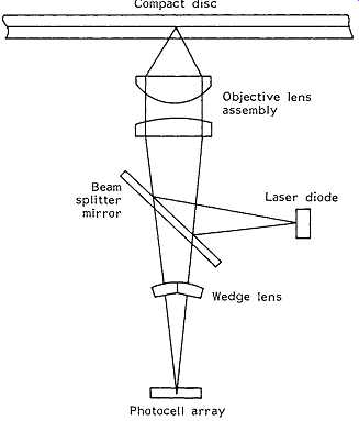
FIG. 8 Single-beam optical read-out system. Compact disc; Photocell array.
The signals representing Ts are generated by a photocell output level transition, either up or down, while '0's are generated electronically within the system by the presence of a timing impulse which is not coincident with a received ‘1’ signal. This confers the valuable feature that the system defaults to a 0 if a data transition is not read, and such random errors can be corrected with ease in the replay system.
It’s necessary to control the position of the lens, in relation both to the disc surface and to the recorded spiral sequence of surface lumps, to a high degree of accuracy. This is done by high speed closed-loop servo mechanism systems, in which the vertical and lateral position of the whole optical read-out assembly is precisely adjusted by electro-mechanical actuators which are caused to operate in a manner which is very similar to the voice coil in a moving coil loudspeaker.
Two alternative arrangements are used for positioning the optical read-out assembly, of which the older layout employs a sled-type arrangement which moves the whole unit in a rectilinear manner across the active face of the disc. This maintains the correct angular position of the head, in relation to the recorded track, necessary when a 'three-beam' track position detector is used. Recent CD replay systems more commonly employ a single-beam lateral/vertical error detection system. Since this is insensitive to the angular relationship between the track and the head, it allows a simple pivoted arm structure to be substituted for the rectilinear-motion sled arrangement. This pivoted arm layout is cheaper to produce, is less sensitive to mechanical shocks, and allows more rapid scanning of the disc surface when searching for tracks.
Some degree of immunity from read-out errors due to scratches and dust on the active surface of the disc is provided by the optical characteristics of the lens which has a sufficiently large aperture and short focal length that the surface of the disc is out of focus when the lens is accurately focused on the plane of the buried mirror layer.
Electronic characteristics
The electronic replay system follows a path closely similar to that used in the encoding of the original recorded signal, though in reverse order, and is shown schematically in FIG. The major differences between the record and replay paths are those such as 'oversampling', 'digital filtering' and 'noise shaping', intended to improve the accuracy of, and reduce the noise level inherent in, the digital-to-analogue transformation.
Referring to FIG. 9, the RF electrical output of the disc replay photocell, after amplification, is fed to a simple signal detection system, which mutes the signal chain in the absence of a received signal, to ensure inter-track silence. If a signal is present, it’s then fed to the 'EFM' (fourteen to eight) decoder stage where the interface and 'joining' bits are removed, and the signal is passed as a group of 8-bit symbols to the 'Cross interleave Reed-Solomon code' (CIRC) error correction circuit, which permits a very high level of signal restoration.
An accurate crystal-controlled clock regeneration circuit then causes the signal data blocks to be withdrawn in correct order from a sequential memory 'shift register' circuit, and reassembled into precisely timed and numerically accurate replicas of the original pairs of 16-bit (left and right channel) digitally encoded signals. The timing information from this stage is also used to control the speed of the disc drive motor and ensure that the signal data are recovered at the correct bit rate.
The remainder of the replay process consists of the stages in which the signal is converted back into analogue form, filtered to remove the unwanted high-frequency components, and reconstructed, as far as possible, as a quantization noise-free copy of the original input waveform.
As noted above, the filtering, and the accuracy of reconstruction of this waveform, are greatly helped by the process of 'oversampling', in which the original sampling rate is increased, on replay, from 44.1 kHz to some multiple of this frequency, such as 176.4 kHz or even higher. This process can be done by a circuit in which the numerical values assigned to the signal at these additional sampling points are obtained by interpolation between the original input digital levels, and as a matter of convenience, the same circuit arrangement will also provide a steep-cut filter having a near-zero transmission at half the sampling frequency.
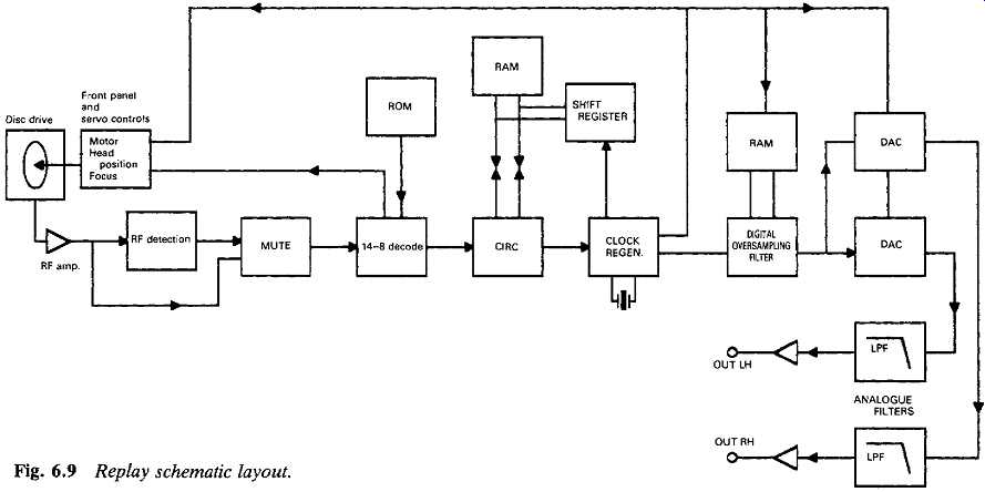
FIG. 9 Replay schematic layout.
THE 'EIGHT TO FOURTEEN MODULATION' TECHNIQUE (EFM)
This is a convenient shorthand term for what should really be described as '8-bit to 14-bit encoding/decoding', and is done for considerations of mechanical convenience in the record/replay process. As noted above, the Ts in the digital signal flow are generated by transitions from low to high, or from high to low, in the undulations on the reflecting surface of the disc.
On a statistical basis, it would clearly be possible, in an 8-bit encoded signal , for a string of eight or more Ts to occur in the bit sequence, the recording of which would require a rapid sequence of surface humps with narrow gaps between them, and this could be inconvenient to manufacture. Also, in the nature of things, these pits or humps will never have absolutely square, clean-cut edges, so the transitions from one sloping edge to another, where there is such a sequence of closely spaced humps, would also lead to a reduction in the replay signal amplitude, and might cause lost data bits.
On the other hand, a long sequence of '0's would leave the mirror surface of the disc unmarked by any signal modulation at all, and, bearing in mind the precise track and focus tolerances demanded by the replay system, this absence of signals at the receiver photocell would embarrass the control systems which seek to regulate the lateral and vertical position of the spot focused on the disc, and which use errors found in the bit repetition frequency, derived from the recovered sequence of Ts and 0s, to correct inaccuracies in the disc rotation speed. All these problems would be worsened in the presence of mechanical vibration.
The method chosen to solve this problem is to translate the 256-bit sequences possible with an 8-bit encoded signal into an alternative series of 256-bit sequences found in a 14-bit code, which are then reassembled into a sequence of symbols as shown graphically in FIG. The requirements for the alternative code are that a minimum of two 0s shall separate each 1, and that no more than ten 0s shall occur in sequence. In the 14-bit code, it’s found that there are 267 values which satisfy this criterion, of which 256 have been chosen, and stored in a ROM- based 'look-up' table. As a result of the EFM process, there are only nine different pit lengths which are cut into the disc surface during recording, varying from three to eleven clock periods in length.
Because the numerical magnitude of the output (EFM) digital sequence is no longer directly related to that of the incoming 8-bit word, the term 'symbol' is used to describe this or other similar groups of bits.
Since the EFM encoding process cannot by itself ensure that the junction between consecutive symbols does not violate the requirements noted above, an 'interface' or 'coupling' group of three bits is also added, at this stage, from the EFM ROM store, at the junction between each of these symbols. This coupling group will take the form of a '???' , ???', ???', or '001' sequence, depending on the position of the '0's or 1s at the end of the EFM symbol. As shown in FIG. 6, this process increases the bit rate from 1.882 MB/s to 4.123 MB/s, and the further addition of uniquely styled 24-bit synchronizing words to hold the system in coherence, and to mark the beginnings of each bit sequence, increases the final signal rate at the output of the recording chain to 4.322 MB/s. These additional joining and synchronizing bits are stripped from the signal when the bit stream is decoded during the replay process.
DIGITAL-TO-ANALOGUE CONVERSION (DAC)
The transformation of the input analogue signal into, and back from, a digitally encoded bit sequence presents a number of problems. These stem from the limited time (22.7 µ8) available for the conversion of each signal sample into its digitally encoded equivalent, and from the very high precision needed in allocating numerical values to each sample. For example, in a 16-bit encoded system the magnitude of the most significant bit (MSB) will be 32 768 times as large as the least significant bit (LSB). Therefore, to preserve the significance of a 0 to 1 transition in the LSB, both the initial and long-term precision of the electronic components used to define the size of the MSB would need to be better than ±0.00305%. (A similar need for accuracy obviously exists also in the ADC used in recording.) Bearing in mind that even a 0.1% tolerance component is an expensive item, such an accuracy requirement would clearly present enormous manufacturing difficulties. In addition, any errors in the sizes of the steps between the LSB and the MSB would lead to waveform distortion during the encoding/decoding process: a distortion which would worsen as the signal became smaller.
Individual manufacturers have their own preferences in the choice of DAC designs, but a system due to Philips is illustrated, schematically, by way of example, in FIG. 10, an arrangement called 'dynamic element matching'. In this circuit, the outputs from a group of current sources, in a binary size sequence from 1 to 1/128, are summed by the amplifier Al5 whose output is taken to a simple 'sample and hold' arrangement to recover the analogue envelope shape from the impulse stream generated by the operation of the ?? input switches (S^Sg). The required precision of the ratios between the input current sources is achieved by the use of switched resistor-capacitor current dividers each of which is only required to divide its input current into two equal streams.
Since in the CD replay process the input '16-bit' encoded signal is divided into two '8-bit' words, representing the MS and LS sections from e1 to e8 and from e9 to e16, these two 8-bit digital words can be separately D/A converted, with the outputs added in an appropriate ratio to give the final 16-bit D/A conversion.
DIGITAL FILTERING AND OVERSAMPLING
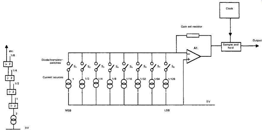
FIG. 10 Dynamic matching DAC. FIG. 11 Comb filter frequency response.
It was noted above that Philips' original choice of sampling frequency (44.1 kHz) and of signal bandwidth (20 Hz to 20 kHz) for the CD imposed the need for steep-cut filtering both prior to the ADC and following the DAC stages. This can lead to problems caused by propagation delays and phase shifts in the filter circuitry which can degrade the sound quality.
Various techniques are available which can lessen these problems, of which the most commonly used come under the headings of 'digital filtering' and 'oversampling'. Since these techniques are interrelated, I have lumped together the descriptions of both of these.
There are two practicable methods of filtering which can be used with digitally encoded signals. For these signals, use can be made of the effect that if a signal is delayed by a time interval, 1s, and this delayed signal is then combined with the original input, signal cancellation - partial or complete - will occur at those frequencies where Ts is equal to the duration of an odd number of half cycles of the signal. This gives what is known as a 'comb filter' response, shown in FIG. 11, and this characteristic can be progressively augmented to approach an ideal low-pass filter response (100% transmission up to some chosen frequency, followed by zero transmission above this frequency) by the use of a number of further signal delay and addition paths having other, carefully chosen, gain coefficients and delay times. (Although, in principle, this technique could also be used on a signal in analogue form, there would be problems in providing a non-distorting time delay mechanism for such a signal - a problem which does not arise in the digital domain.) However, this comb filter type arrangement is not very conveniently suited to a system, such as the replay path for a CD, in which all operations are synchronized at a single specific 'clock' frequency or its sub-multiples, and an alternative digital filter layout, shown in FIG. 12 in simplified schematic form, is normally adopted instead. This provides a very steep-cut low-pass filter characteristic by operations carried out on the signal in its binary encoded digital form.
In this circuit, the delay blocks are 'shift registers', through which the signal passes in a 'first in, first out' sequence at a rate determined by the clock frequency. Filtering is achieved in this system by reconstructing the impulse response of the desired low-pass filter circuit, such as that shown in FIG. 13. The philosophical argument is that if a circuit can be made to have the same impulse response as the desired low-pass filter it will also have the same gain/frequency characteristics as that filter - a postulate which experiment shows to be true.
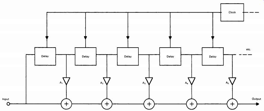
FIG. 12
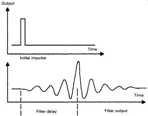
FIG. 13 Impulse response of low-pass FIR filter. Zeros are 1/fs apart; cut-off
frequency = fc/2. --- Initial impulse -- Filter output
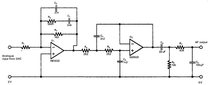
FIG. 14 Linear phase LP filter.
This required impulse response is built up by progressive additions to the signal as it passes along the input-to-output path, at each stage of which the successive delayed binary coded contributions are modified by a sequence of mathematical operations. These are carried out, according to appropriate algorithms, stored in 'look-up' tables, by the coefficient multipliers A1, A2, A3, . . . , An. (The purpose of these mathematical manipulations is, in effect, to ensure that those components of the signal which recur more frequently than would be permitted by the notional 'cut-off frequency of the filter will all have a coded equivalent to zero magnitude.) Each additional stage has the same attenuation rate as a single-pole RC filter (-6 dB/octave), but with a strictly linear phase characteristic, which leads to zero group delay.
This type of filter is known either as a 'transversal filter', from the way in which the signal passes through it, or a 'finite impulse response' (FIR) filter, because of the deliberate omission from its synthesized impulse response characteristics of later contributions from the coefficient multipliers. (There is no point in adding further terms to the A1, . . . , An series when the values of these operators tend to zero.) Some contemporary filters of this kind use 128 sequential 'taps' to the transmission chain, giving the equivalent of a -768 dB/octave low-pass filter. This demonstrates, incidentally, the advantage of handling signals in the digital domain, in that a 128-stage analogue filter would be very complex and also have an unacceptably high thermal noise background.
If the FIR clock frequency is increased to 176.4 kHz, the action of the shift registers will be to generate three further signal samples, and to interpolate these additional samples between those given by the original 44.1 kHz sampling intervals - a process which would be termed 'four times oversampling'. The simple sample-and-hold stage, at the output of the DAC shown in FIG. 10, will also assist filtering since it will attenuate any signals occurring at the clock frequency, to an extent determined by the duration of the sampling operation - called the sampling 'window'. If the window length is near 100% of the cycle time the attenuation of the S/H circuit will be nearly total at /s.
Oversampling, on its own, would have the advantage of pushing the aliasing frequency up to a higher value, which makes the design of the anti-aliasing and waveform reconstruction filter a much easier task to accomplish, using simple analogue-mode low-pass filters whose characteristics can be tailored so that they introduce very little unwanted group delay and phase shift. A typical example of this approach is the linear phase analogue filter design, shown in FIG. 14, used following the final 16-bit DACs in the replay chain.
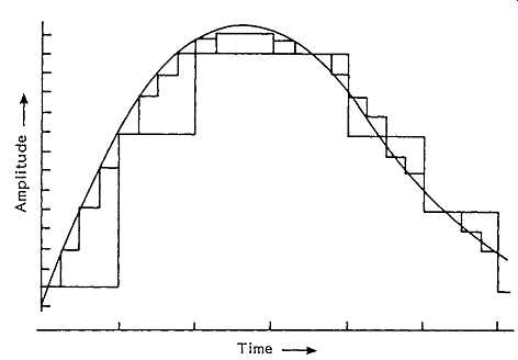
FIG. 15 Effect of four times oversampling and interpolation of intermediate
values.
However, the FIR filter shown in FIG. 12 has the additional effect of computing intermediate numerical values for the samples interpolated between the original 44.1 kHz input data, which makes the discontinuities in the PCM step waveform smaller, as shown in FIG. 15. This reduces the quantization noise and also increases the effective resolution of the DAC. As a general rule, an increase in the replay sampling rate gives an improvement in resolution which is equivalent to that given by a similar increase in encoding level - such that a four times oversampled 14-bit decoder would have the same resolution as a straight 16-bit decoder.
Yet another advantage of oversampling is that it increases the bandwidth over which the 'quantization noise' will be spread - from 22.05 kHz to 88.2 kHz in the case of a four times oversampling system. This reduces the proportion of the total noise which is now present within the audible (20 Hz to 20 kHz) part of the frequency spectrum - especially if 'noise shaping' is also employed. I will examine this aspect later in this SECTION.
DITHER
If a high-frequency noise signal is added to the waveform at the input to the ADC, and if the peak-to-peak amplitude of this noise signal is equal to the quantization step 'Q', both the resolution and the dynamic range of the converter will be increased. The reason for this can be seen if we consider what would happen if the actual analogue signal level were to lie somewhere between two quantization levels. Suppose , for example, in the case of an ADC, that the input signal had a level of 12.4, and the nearest quantization levels were 12 and 13. If dither had been added, and a sufficient number of samples were taken, one after another, there would be a statistical probability that 60% of these would be attributed to level 12, and 40% would be attributed to level 13, so that, on averaging, the final analogue output from the ADC/DAC process would have the correct value of 12.4.
A further benefit is obtained by the addition of dither at the output of the replay DACs (most simply contrived by allowing the requisite amount of noise in the following analogue low-pass filters) in that it will tend to mask the quantization 'granularity' of the recovered signal at low bit levels.
This defect is particularly noticeable when the signal frequency happens to have a harmonic relationship with the sampling frequency.
THE 'BITSTREAM' PROCESS AND 'NOISE SHAPING'
A problem in any analogue-to-digital or digital-to-analogue converter is that of obtaining an adequate degree of precision in the magnitudes of the digitally encoded steps. It has been seen that the accuracy required, in the most significant bit in a 16-bit converter, was better than 0.00305% if '?'-'G transitions in the LSB were to be significant. Similar, though lower, orders of accuracy are required from all the intermediate step values.
Achieving this order of accuracy in a mass-produced consumer article is difficult and expensive. In fact, differences in tonal quality between CD players are likely to be due, in part, to inadequate precision in the DACs.
As a means of avoiding the need for high precision in the DAC converters, Philips took advantage of the fact that an effective improvement in resolution could be achieved merely by increasing the sampling rate, and this could then be traded-off against the number of bits in the quantization level. Furthermore, whatever binary encoding system is adopted, the first bit in the received 16-bit word must always be either a 0 or a 1, and in the 'two's complement' code used in the CD system, the transition in the MSB from 0 to 1 and back will occur at the mid-point of the input analogue signal waveform.
This means that if the remaining 15 bits of a 16-bit input word are stripped off and discarded, this action will have the effect that the input digital signal will have been converted - admittedly somewhat crudely -- into a voltage waveform of analogue form. Now, if this ?/G signal is 256 times oversampled, in the presence of dither, an effective 9-bit resolution will be obtained from two clearly defined and easily stabilized quantization levels: a process for which Philips have coined the term 'Bitstream' decoding.
Unfortunately, such a low-resolution quantization process will incur severe quantization errors, manifest as a high background noise level.
Philips' solution to this is to employ 'noise shaping', a procedure in which, as shown in FIG. 16, the noise components are largely shifted out of the 20 Hz to 20 kHz audible region into the inaudible upper reaches of the new 11.29 MHz bandwidth.
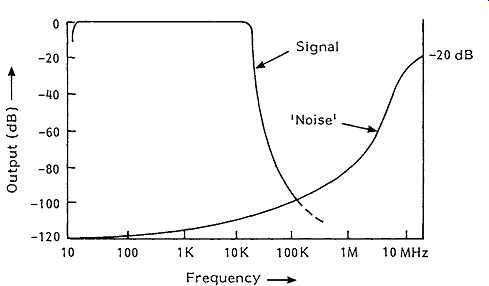
FIG. 16 Signal/noise spectrum after 'noise-shaping'.
The proposition is, in effect, that a decoded digital signal consists of the pure signal, plus a noise component (caused by the quantization error) related to the lack of resolution of the decoding process. It’s further argued that if this noise component is removed by filtering what remains will be the pure signal - no matter how poor the actual resolution of the decoder. Although this seems an unlikely hypothesis, users of CD players employing the 'Bitstream' system seem to agree that the technique does indeed work in practice. It would seem therefore that the greater freedom from distortion, which could be caused by errors in the quantization levels in high bit-level DACs, compensates for the crudity of a decoding system based on so few quantization steps.
Mornington-West (Newnes Audio and Hi-Fi Hand guide (2nd edition, p. 141) quotes oversampling values of 758 and 1024 times respectively for Technics' and 'Sony' 'low-bit' CD players, which would be equivalent in resolution to 10.5-bit and 11-bit quantization if a simple ?' or T choice of encoding levels was used. Since the presence of dither adds an effective 1-bit to the resolution and dynamic range, the final figures would become 10-, 11.5- and 12-bit resolution respectively for the Philips, Technics and Sony CD players.
However, such decoders need not use the single-bit resolution adopted by Philips, and if a 2-bit or 4-bit quantization was chosen as the base to which the oversampling process was applied - an option which would not incur significant problems with accuracy of quantization - this would provide low-bit resolution values as good as the 16-bit equivalents, at a lower manufacturing cost and with greater reproducibility. Ultimately, the limit to the resolution possible with a multiple sampling decoder is set by the time 'jitter' in the switching cycles and the practicable operating speeds of the digital logic elements used in the shift registers and adders. In the case of the 1024 times oversampling 'Sony' system, a 44.1584 MHz clock speed is required, which is near the currently available limit.
ERROR CORRECTION
The possibility of detecting and correcting replay errors offered by digital audio techniques is possibly the largest single benefit offered by this process, because it allows the click-free, noise-free background level in which the CD differs so obviously from its vinyl predecessors. Indeed, were error correction not possible, the requirements for precision of the CD manufacturing and replay process would not be practicable.
Four possible options exist for the avoidance of audible signal errors, once these have been detected. These are: the replacement of the faulty word or group of words by correct ones: the substitution of the last correct word for the one found to be faulty - on the grounds that an audio signal is likely to change relatively slowly in amplitude in comparison with the 44.1 kHz sample rate: linear interpolation of intermediate sample values in the gaps caused by the deletion of incorrectly received words, and, if the worst comes to the worst, the muting of the signal for the duration of the error.
Of these options, the replacement of the faulty word, or group of words, by a correct equivalent is clearly the first preference, though it will, in practice, be supplemented by the other error-concealment techniques. The error correction system used in the CD replay process combines a number of error correction features and is called the 'Cross-interleave Reed-Solomon Code' (CIRC) system. It’s capable of correcting an error of 3500 bits, and of concealing errors of up to 12000 bits by linear interpolation. I will look at the CIRC system later, but, meanwhile, it will be helpful to consider some of the options which are available.
Error detection:
The errors which are likely to occur in a digitally encoded replay process are described as 'random' when they affect single bits and 'burst' when they affect whole words or groups of words. Correcting random errors is easier, so the procedure used in the Reed-Solomon code endeavors to break down burst errors into groups of scattered random errors. However, it greatly facilitates remedial action if the presence and location of the error can be detected and 'flagged' by some added symbol.
Although the existence of an erroneous bit in an input word can sometimes be detected merely by noting a wrong word length, the basic method of detecting an error in received words is by the use of 'parity bits'. In its simplest form, this would be done by adding an additional bit to the word sequence, as shown in FIG. 17(a), so that the total (using the logic rules shown in the figure) always added up to zero (a method known as 'even parity'). If this addition had been made to all incoming words, the presence of a word plus parity bit which did not add up to ?' could be detected instantly by a simple computer algorithm, and it could then be rejected or modified.
FIG. 17 Parity bit error correction. Logic: 0 + 0 = 0, 0 + 1 = 1, 1 + 1 = 0.
Faulty bit/word replacement:
Although the procedure shown above would alert the decoder to the fact that the word was in error, the method could not distinguish between an incorrect word and an incorrect parity bit - or even detect a word containing two separate errors, though this might be a rare event.
However, the addition of extra parity bits can indeed correct such errors as well as detect them, and a way by which this could be done is shown in FIG. 17(b). If a group of four 4-bit input words, as shown in lines a-d, each has a parity bit attached to it, as shown in column q, so that each line has an even parity, and if each column has a parity bit attached to it , for the same purpose, as shown in line e, then an error, as shown in grid reference (b.n) in FIG. 17(c), could not only be detected and localized as occurring at the intersection of row b and column n, but it could also be corrected, since if the received value ?' is wrong, the correct alternative must be T . Moreover, the fact that the parity bits of column q and row e both have even parity means that, in this example, the parity bits themselves are correct. If the error had occurred instead in one of the parity bits, as in FIG. 17(d), this would have been shown up by the fact that the loss of parity occurred only in a single row - not in both a row and a column.
So far, the addition of redundant parity bit information has offered the possibility of detecting and correcting single bit Random' errors, but this would not be of assistance in correcting longer duration 'burst' errors, comprising one or more words. This can be done by 'interleaving', the name which is given to the deliberate and methodical scrambling of words, or the bits within words, by selectively delaying them, and then re-inserting them into the bit sequence at later points, as shown in FIG. 18. This has the effect of converting a burst error, after de-interleaving, into a scattered group of random errors, a type of fault which is much easier to correct.
A further step towards the correction of larger-duration errors can be made by the use of a technique known as 'cross-interleaving'. This is done by reassembling the scrambled data into 8-bit groups without descrambling. (It’s customary to refer to these groups of bits as 'symbols' rather than words because they are unrelated to the signal.) Following this, these symbols are themselves mixed up in their order by removal and re-insertion at different delay intervals. In order to do this it’s necessary to have large bit-capacity shift registers, as well as a fast microprocessor which can manipulate the information needed to direct the final descrambling sequences, and generate and insert the restored and corrected signal words.
To summarize, errors in signals in digital form can be corrected by a variety of procedures. In particular, errors in individual bits can be corrected by the appropriate addition of parity bits, and burst errors affecting words, or groups of words, can be corrected by interleaving and de-interleaving the signal before and after transmission - a process which separates and redistributes the errors as random bit faults, correctable by parity techniques.
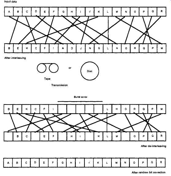
FIG. 18 Burst error correction by interleaving. --- After de-interleaving;
After random bit correction
A variety of strategies has been devised for this process, aimed at achieving the greatest degree of error removal for the lowest necessary number of added parity bits. The CIRC error correction process used for CDs is very efficient in this respect, since it only demands an increase in transmitted data of 33.3%, and yet can correct burst errors up to 3500 bits in length. It can conceal, by interpolation, transmission errors up to 12 000 bits in duration - an ability which has contributed enormously to the sound quality of the CD player by comparison with the vinyl disc.
From the point of view of the CD manufacturer, it’s convenient that the complete CIRC replay error correction and concealment package is available from several IC suppliers as part of a single large-scale integrated (LSI) chip. From the point of view of the serious CD user, it’s preferable that the error correction system has to do no more work than it must, since although the errors will mainly be restored quite precisely, it may be necessary, sometimes , for the system to substitute approximate, interpolated values for the signal data, and the effect of frequent corrections may be audible to the critical listener. So treat CDs with care, keep them clean, and try to avoid surface scratches.