AMAZON multi-meters discounts AMAZON oscilloscope discounts
Most people have enjoyed looking at a hologram, but few people have made one. But if just looking at a hologram is such fun, imagine what its like to make your own. The last section introduced the basics of holography and showed you how to make your own transmission-type holograms. This section takes you several steps further, revealing how to make colorful reflection holograms, circular holograms, or even holographic movies. There are also several alternative setups for both transmission and reflection holograms you might like to try.
ADVANCED SANDBOX
The 2-by-2-foot sandbox described in the last section is fine for tinkering around, but serious holography requires a bigger work area. Ill. 18-1 shows a design for a 4-by-4-foot sandbox using plywood, concrete blocks, poured concrete, and automobile inner tubes. A parts list is provided in TABLE 18-1. The table uses basic masonry and concrete-pouring techniques, so if you aren’t familiar with these, pick up any good book on the subject at the library. Although the procedure of pouring and leveling concrete might seem too involved, it’s actually a simple process that takes just one or two hours.
Start the table by laying a 4-by-4-foot carpet on the floor. Place five concrete blocks, each measuring 8 by 8 by 16 inches, over the carpet, as shown in ill. 18-2. Add small pieces of carpet on top of the blocks, then set a 3 piece of 4-by-4-foot plywood squarely over the blocks. Add yet another piece of carpet over the plywood.
Inflate four small automobile or motorcycle inner tubes to 50 to 60 percent full. Don’t overfill—just inflate enough so that the inner tube starts to expand and that a heavy weight placed on top won't squeeze the rubber together. Inner tubes for small 12- or 13-inch car wheels work well. Alternatively, you can use wide motorcycle-tire inner tubes. Use a fifth tube in the middle of the table if the tubes are very small.
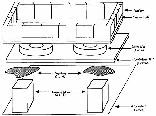
ill. 18-1. Materials required to make the 4-by-4 -foot concrete
sand table.
Table 18-1. Large Sand Table Parts Lists
Base and Pedestal:
- 5 Cement building blocks (8 by 8 by 16 inches)
- 5 8-inch-square pieces of carpet
- 1 4-foot-square piece of carpeting
- 4 10- to 14-inch inner tubes
- 1 4-by-4-foot sheet of ¾-inch-thick plywood
Sand Box:
- 1 4-by-4-foot sheet of ¾-inch-thick plywood
- 16 12-by-12-inch-square stepping stones (or equivalent)
- 4 48-inch lengths of 2-by-4 framing lumber (for cement slab)
- 2 Bags Redi-Mix (or similar) cement
- 1 Bag mortar mix
- 1 4-by-4-foot piece of chicken wire
- 4 75- or 100-pound bags of washed, sterilized, and filtered sand
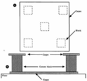
ill. 18-2. Placement of the carpet and blocks. (A) Top view; (B) Side
view.
Cut a piece of plywood to 4 by 4 feet. Nail 2-by-4 framing to the outside edge of the plywood. Use only a few nails for each side; the framing is temporary. Mix two bags of Redi-Mix (or similar) cement according to instructions. In most cases, all you add is water. An old wash-bucket makes a good mixing bin. Lay a piece of plastic tarpaulin in the box to prevent cement from oozing out the sides. Fill the box about 1‘/3-full with cement, then place a piece of 4-by-4-foot chicken wire (trim the chicken wire so that it fits) on top of the cement. Pour the remaining concrete over the chicken wire.
The concrete should reach the top of the box. If it doesn’t, mix a little more, but you don’t need to use a whole bag. Use a piece of scrap 2-by-4 as a leveling board to smooth out the concrete. Once the cement is leveled, leave it alone overnight. Read the instructions that came with the cement to see if you should water the slab as it dries to prevent cracking. If watering is recommended, sprinkle a small amount of water on the slab every few hours. Should the slab be cracked after drying, fill it using concrete filling cement, available at most building supply stores. After the slab has dried (the cement is now concrete), remove the 2-by-4 frame pieces and trim away the tarpaulin.
Now arrange a series of stepping stones around the perimeter of the slab as shown in ill. 18-3. The size of the stepping stones doesn’t matter as long as they are about 1 inch thick. A common stepping stone size is 12 by 12 inches; you don’t need anything fancy (don’t buy colored or fluted stones).
Mortar mix
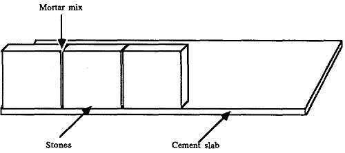
ill. 18-3. Adding square stepping stones to the perimeter of the concrete
slab. Use mortar to set the stones.
Prepare a bucket of mortar mix according to instructions. With a trowel, glop the mortar onto the bottom and sides of the stones and apply them to the perimeter of the slab (you might need to wet the slab and stones first with clean water). Work slowly and try to use just the right amount of mortar, but you can scrape off mortar that oozes between the stones with the trowel.
If the stones you use won’t fit evenly around the perimeter of the slab—the corners don’t meet, for example—you can cut them into smaller pieces by first making a scoring line. Score the stone with a hacksaw at the place where you want to make the cut. After the score is ¼- to ¼-inch deep, place the stone at a curb or other ledge. Press down with both hands to break the stone at the score. Your first attempt might not work, but with practice, you’ll get the hang of it. You can also use smaller stepping stones or even red brick to fill in corners that don’t meet.
The mortar takes about a day to dry and might also require a sprinkle now and then with water to prevent cracking. After the mortar has set, add 16 to 18 100-pound bags of sand. Fill to about 2 inches from the top of the table. At this point, you may want to remember that the table will weigh about a ton when filled with sand, so if you put the table on a rickety floor, you’ll soon regret it.
The sand table is now complete. Some holographers like to paint the concrete flat black to reduce light scatter and to improve the looks. Painting isn't necessary, but do as you please.
MAKING A REFLECTION HOLOGRAM
Transmission holograms require you to shine the expanded beam of a laser through them in order to see an image. Another type of hologram that doesn’t require a laser for viewing is the reflection hologram. These work by shining light (white or colored) off the diffraction grating surface of the hologram. If viewed under white light, the hologram gives off a rainbow of dazzling colors.

ill. 18-4. Basic single-beam reflection hologram arrangement.
Mixing the Chemicals
Reflection holograms are no more difficult to make than transmission holograms, although the processing chemistry is a bit different. White-light reflection holograms can use Kodak D-19 developer but should be bleached using one of the following formulas:
+ Carefully mix 20 grams (or about one tablespoon) of potassium bromide and 20 grams mercuric chloride (fatal if swallowed) in one liter of water. This stuff is dangerous and highly caustic, so never touch it with bare fingers or allow it to splash on skin, clothes, or eyes.
Or,
+ Dissolve two grams of potassium dichromate with 30 grams of potassium bromide in one liter of water. After these have thoroughly mixed, carefully add two cm of concentrated sulfuric acid (always add acid to water, not the other way around). This is also nasty stuff and will burn skin if you touch it. Wear gloves and safety goggles when mixing, and use gloves or tongs when processing the film.
The best reflection holograms need a fixing step, just like regular photographic film and paper. Fixer comes pre-made (in powder or liquid), making it easy to use. Kodak Rapid Fixer with hardener is a good choice. Mix according to instructions.
Setting Up
Ill. 18-4 shows the most rudimentary arrangement for making a reflection hologram. See TABLE 18-2 for a parts list. Position the laser, lens, film, and object in a direct line. For best results, the object used in reflection-type holography should be relatively small in comparison to the film and should be placed within a few inches of the film. Larger images or those placed far away tend to be dark and fuzzy.
As you read in the last section, reflection holograms require a film without the antihalation backing; be sure to use this type. When you are ready to make the exposure, turn out the lights, remove the film, and place the film in the holder.
If you are using a glass-plate film holder, remember to press the plates together firmly and keep constant pressure for 10 to 20 seconds to remove air bubbles trapped between the glass and film. Use wood blocks to apply even pressure. Snap the binder clips around the glass and position the holder in front of the object. If necessary, mount the film holder between two PVC or dowel pillars.
As with the transmission hologram, the beam should be expanded so that the outer ‘/3 of the diameter falls off the edge of the film. You want the inner 2/3 of the beam, which is the brightest portion. Unlike transmission holograms, reflection holograms call for a ratio between reference and object at a more even 1:1 or 2:1. Use a photographic light meter or power meter to determine proper beam ratios.
Exposure time depends on the power output of the laser as well as the size of the film (or more precisely, the amount of beam spreading), but you might have luck using trial exposures of 3 to 5 seconds with a 1 mW laser and a 1 to 2 seconds for a 3 mW laser.
Processing the Film
In dim or green-filtered light, dip the film in the developer tray and process for 2 to 5 minutes. As a general rule of thumb, a reflection hologram should pass about 20 to 30 percent of the light when held up to a green safelight. After developing, rinse in water or stop bath for 15 seconds.
Dip the film in the first fixer bath for 2 to 3 minutes. After fixing is complete, the room lights can be turned on (fixer renders the film insensitive to further exposure to light). Wash again in water for 15 seconds.
Place the film in the bleach mixture for 1 to 2 minutes or until the film clears. Rinse once more in water for 15 seconds. Finally, place the film in a second fixer bath for 3-5 minutes or until the hologram turns a brown color.
Wash all the chemicals away by rinsing the film under running water for at least five minutes. Then, dip the hologram in Photoflo, squeegee it, and hang it up to dry (details on these last steps are in the previous section). Be aware that you can’t see a holographic image until the film is completely dried, so don’t judge your success (or failure) at this point.
If you are impatient and can’t wait for the film to dry on its own, you can hurry up the process by blow-drying the film with a hair dryer. Set the dryer on no heat (air only) and gently waft it 6 to 8 inches in front of the film. The backing will dry quickly but the emulsion takes 5-10 minutes. Always remember to dry film in a dust-free place. Amateur photographers like to use the tub or shower in the bathroom, a place where airborne dust usually doesn’t stay for long.
Table 18-2. Single Beam Reflection Hologram Setup Parts List
- 1 He-Ne laser
- 1 8 to 10 mm bi-concave lens
- 1 Holographic film in film holder
To sum up:
* Develop in D-i9 (or similar) developer for 2 to 5 minutes.
1 Object
* Rinse in water or stop bath for 15 seconds.
* Fix in first fixer for 2 to 3 minutes (light on after fixing).
* Rinse in water for 15 seconds.
* Bleach for 1 to 2 minutes (or until the film clears).
* Rinse in water for 15 seconds.
* Fix in second fixer for 3 to 5 minutes.
* Wash thoroughly under running water for 5 + minutes.
* Dip in Photoflo for 15 seconds; squeegee.
* Dry for at least 30 minutes.
Alternate Method
A slightly less complex processing method can be used to make reflection holograms. Develop the film in D-19 for 2 to 5 minutes, then wash in running water for 5 minutes. Bleach the film using the sulfuric acid bleach described above for 2 minutes or until the film clears (becomes transparent). Wash another 5 to 10 minutes and dry it.
VIEWING REFLECTION HOLOGRAMS
Reflection holograms don’t require a laser for image reconstruction. Just about any source of light will work, including sunlight or the light from an incandescent light. Avoid greatly diffused light such as that from a fluorescent lamp, or the hologram will look fuzzy. The ideal light source is a point-source, such as an unfrosted filament bulb. You will see the image as you tilt the hologram at angles to the light.
Note the many colors in the picture, particularly green. Although made with a red helium-neon light, the film shrinks after processing, so it tends to reflect shorter wave length light. The amount of shrinkage varies depending on the film, but it often correlates to 50 to 100 nanometers, reducing the red 632.8 nm wavelength of the a helium-neon laser to about 500 to 550 nm.
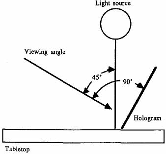
ill. 18-5. How to view the processed (and dried) reflection hologram in
white light.
ill. 18-6. Optical arrangement (shown in the sandbox) for a multiple-beam reflection hologram. The object is illuminated on two sides, providing even lighting and better contrast.
The best viewing setup for a reflection hologram is shown in ill. 18-5. Place the light from a desk lamp straight down at the table. Tilt the hologram toward you until the image becomes clear (about 45 to 50 degrees).
IMPROVED REFLECTION HOLOGRAMS
There are a number of methods to make better and more interesting reflection holograms. One is to use a casting or mold for an object and place the mold directly behind the film. The hologram that results has an eerie 3-D quality to it where you can’t tell if the object is concave or convex. Try it.
A split-beam reflection hologram provides more even lighting and helps improve the three-dimensional quality. Ill. 18-6 shows one arrangement you can use. Except for the angle of some of the objects, it's nearly identical to the split-beam transmission hologram setup described in the last section.
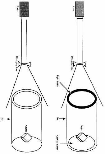
ill. 18-7. How to make a single-beam cylindrical hologram. ill. 18-8. Another
approach to the cylindrical hologram, without the mirror and light baffle.
Table 18-3. Split-Beam Transmission Hologram Parts List
- 1 He-Ne laser
- 3 8 to 10 mm bi-concave lens
- 1 Holographic film in film holder
- 4 1- to 2-inch-square front-surface mirror
- 2 Plate beam splitter (50:50)
- 3 Black blocking card
- 1 Object
Table 18-4. Cylindrical Hologram Setup Parts List
- 1 Laser
- 1 8 to 10 mm bi-concave lens
- 1 3-inch diameter (approximately) clear glass or plastic jar (length 2 to 4 inches)
- 1 3-inch diameter (approximately) convex mirror
- 1 Object on pedestal
- 1 Film Strip
- 1 Light baffle
ADVANCED HOLOGRAPHIC SETUPS
A one-mirror cylindrical transmission hologram can be made using the basic arrangement depicted in ill. 18-7 (refer to TABLE 184 for a parts list). You need wide film for this project; you can either buy it in 70-by-250-mm strips, or cut even larger film to size. The setup is relatively simple. A glass or plastic jar (approximately 3 inches in diameter) holds a convex mirror and the object. Inside the jar, wrap a strip of film so that the emulsion is facing inward. A light baffle made of black art board, placed at the neck of the jar, prevents laser light from spilling directly onto the film.
In operation, the laser light directly illuminates the object as well as the mirror. The light from the mirror acts as the reference beam. The light from both object and mirror meets at all areas around the circumference of the jar, exposing the entire piece of film. The object shows up better if it's mounted on a pedestal. A small piece of wood painted flat black works well as a pedestal.
Process the film as usual, but be sure the trays are large enough to accommodate the film. To view the hologram, wrap it in a circle and shine an expanded laser beam through the top and against one inside wall. View the film by rotating it. You can support the film by placing it back inside the jar you used for making the hologram.
A reflection hologram is made by changing the convex mirror for a concave one (many such mirrors are coated on both sides so that they are concave/convex). To view the hologram, shine a point source of white light through the top and against one inside wall.
Any object that you can fit in the jar and place on the pedestal can be used for a cylindrical hologram. Good choices for first attempts include chess pieces, old coins (held upright on one edge), and playing dice. If the object doesn’t sit the way you want on the pedestal, secure it in place using black modeling clay (not the best method) or Super Glue. Most objects will snap off even with Super Glue, particularly if you apply just a dab on top of the pedestal.
The biggest problem with this method is movement of the film during exposure. Wait at least 5 minutes after loading the film to expose it to allow time for the film to shift and settle. You might want to tap the jar once or twice after placing the film to help set it in position. Leave it alone while you take a coffee break (or better yet, take in a half-hour sitcom).
Direct Beam Cylindrical
Another type of cylindrical hologram doesn’t use a mirror. The direct beam cylindrical arrangement shown in ill. 18-8 makes transmission-type holograms of objects you’ve mounted on a black pedestal. See TABLE 18-5 for a parts list. The setup requires a well- expanded beam of laser light, so you might need to use two bi-concave lenses, positioned one after the other, to achieve the desired effect.
If you use non-AH film (film without an antihalation backing), you might want to cover the outside of jar with black construction paper to prevent the film from being fogged by stray light that strikes the outside of the jar. Once again, be sure to place the film securely in the jar. Place tape on the top portion of the film to keep it from moving; wait at least 10 to 15 minutes for the film to settle.
Directing the Beam
It is easiest to expose objects by placing the jar sideways on the sand table. That requires you to mount the pedestal and object to the mirror and secure the mirror to the base of the jar. When this isn’t practical or desirable, you may place the jar upright and direct the beam into the jar with a large front-surface mirror.
While this approach works, it’s not highly recommended, because dust, fingerprints, and other contamination on the mirror can upset the exposure. Reflected laser light is never as pure when it's expanded to cover a wide area. Whenever possible, laser light should be unexpanded when bounced off mirrors.
Multiple-Channel Holograms
A transmission hologram must always be positioned so that the illumination from the laser is at the same angle as the reference beam when the picture was first taken.
Table 18-5. Cylindrical Hologram Setup Parts List
- 1 Laser
- 1 8 to 10 mm bi-concave lens
- 1 3-inch diameter (approximately) clear glass or plastic jar (length 2 to 4 inches)
- 1 Object on pedestal
- 1 Film strip
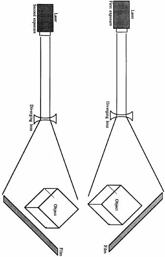
ill. 18-9. How to make a multiple-channel hologram. Shown are locations
for the film holder for the first and second exposures of the same object.
Canting the film at an angle makes the image disappear. While this is often considered a nuisance by beginning holographers, it’s actually a considerable benefit because it means you can expose the same piece of film with an almost unlimited number of scenes! You see each scene by rotating the film or by shifting its angle relative to the illumination beam. This process is most often called multiple-channel holography, and it takes many forms.
In practice, you want to limit the number of exposures to two or four. The more scenes recorded on the film, the more chance they will interfere with one another. The objects for multiple-channel holography should be relatively small in comparison to the size of film you are using. A good rule of thumb for a two-channel hologram (one that has two separate images on it) is that the subjects should be about half the size of the film. In a four-channel hologram, the subjects should be approximately one-quarter the size of the film.
Other forms of multiple channel holograms, including multiplex still-film holography, can accommodate hundreds and even thousands of separate images when the area of exposure is controlled. Multiplex still-film holography (or holographic stereograms) use frames of movie film recorded as slits on the hologram. After processing, the film is wrapped in a circle and you see each “frame” as the slits roll by.
A famous example is this “Kiss,” created by Lloyd Cross and Pam Brazier, where a woman blows a kiss, then winks. The technique is fascinating but beyond the scope of this book. For more information on this holographic technique (as well as numerous others), consult Holography Handbook, by Fred Unterseher, et al.
To make a simple multiple-channel hologram, arrange the laser and optics as shown in ill. 18-9. Position the film to produce a standard direct-beam transmission hologram. Make the first exposure but at about half the normal time. Shift the position of the film and change subjects (you can also use the same subject, if desired). Make the second exposure, again at about half the normal time. Be sure that the emulsion faces the object and reference beam for both exposures. For best results, the angle of the film should change by 60 to 90 degrees.
After processing, illuminate the hologram in the usual manner. Note how you see object A when the film is tilted one way, then object B when the film is tilted the other way. If you used the same object for both exposures and the angle of the film was roughly 90 degrees, rotating the film will reveal almost 180 degrees of the object.
Instead of physically moving the film, you can rotate it in its holder. E.g., you can make a four-channel hologram by rotating the film 90 degrees for each new exposure (exposure time about one-fourth of normal). When viewing the hologram, you see the different views of different objects by spinning the film.
HOLOGRAM GALLERY
Below are several setups you might want to use to create a wide variety of holograms. Included are both transmission and reflection types, using single and multiple beams. In all cases, remember to follow standard holographic practices:
* Allow time for the table and film to stabilize before taking the exposure.
* When using glass-plate film holders, be sure the glass is perfectly clean. Press both pieces firmly together for about 30 seconds. Use blocks of wood to exert even pressure. Remove all the trapped air, or the film might move during the exposure.
* Be sure to place the film so that the emulsion faces the subject and /or reference beam. This isn’t always necessary for reflection-type holograms, but it's a good habit.
* Observe proper lighting ratios between reference and object beams. Generally, transmission holograms have a 3:1 or 4:1 ratio between reference and object beams (but up to 10:1 is sometimes required to eliminate noise); reflection holograms have a 1:1 or 2:1 ratio.
* Measure distances for reference and object beams to ensure they are approximately equal. Use a cloth or flexible tape.
* Use the proper chemicals mixed fresh (or stored properly), as per directions. Throw out exhausted chemicals—flush them down the sink and run plenty of water to wash away the chemical residue.
Holographic Interferometry
Ill. 18-10 shows the basic setup for experimenting with holographic interferometry, a type of metrologic study where you can visually see how an object moves under stress. An interferometric hologram is made with two exposures: one where the object under test is “at rest,” and other when it's “under stress.” Slight differences in shape and structure can occur between the two states, causing movement that shows up in the two exposures. The amount and type of movement is clearly visible in the form of interference lines.
To make an interferometric hologram, take one exposure of the object (a ruler in the example) at about half-normal time—that is, if the usual exposure is 3 seconds re duce it to 1.5 seconds. Then, without disturbing anything, apply stress (the weight) to the object and after allowing time for settling, take another exposure. It is important that you don't disturb anything in the setup other than to carefully apply the weight.
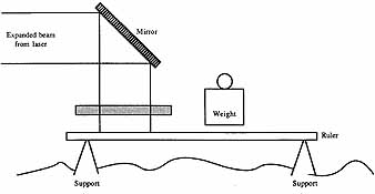
ill. 18-10. The basic arrangement for making interference holograms.
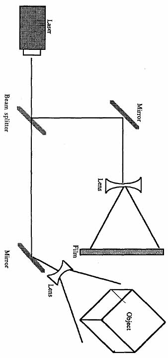
ill. 18-11. An alternative scheme for producing a multiple-beam reflection
hologram.
If the ruler, film, or other components shift even a few millionths of an inch, the hologram will be ruined. Don’t expect to get this one right the first time. It requires a great deal of patience and careful arrangement.
If the ruler doesn’t prove a cooperative subject, try another. One good choice is a small C-clamp pressed tightly around a steel plastic block. Take one picture with the clamp tightened, but not overly so, on the block. Cinch down on the clamp and take another exposure. You will see stress marks around the C-shaped mouth of the clamp as well as at the point of contact on the block. Other possible subjects include a light bulb in both cold and hot states (turn the bulb on for a few minutes between exposures, but be sure to block the film from exposure), and the strain on a piece of metal from an increased electromagnetic current.
Multiple-Beam Reflection Hologram
The setup in ill. 18-11 shows another arrangement you can use to make a multiple- beam reflection hologram. It is a more simple approach to the multiple beam plan de scribed earlier in this section and doesn’t provide the same even lighting of the object, but it’s easy to arrange for classroom study.
Soft Lighting Technique
Transmission holograms often suffer from high-contrast lighting where the shadows have little detail. While this can enhance the three-dimensional quality of the image, the lighting effect is unnatural. Ill. 18-12 shows how you can soften the lighting to achieve a less dramatic appearance. The reference beam is directed towards the film as usual, but the object beam is diffused using opal or frosted glass.
Note that the glass acts as a mirror on the back side so you should add black cards as necessary to avoid light spills. Expand the beam slightly before striking the back of the glass to avoid a hot spot in the center. Try exposure times slightly longer than normal.
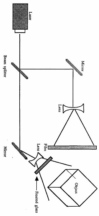
ill. 18-12. One way to provide soft lighting for the object is to place
a piece of frosted glass in the path of the expanded object beam.
Downward Facing Hologram
A simple form of single-beam transmission holography entails pointing the film to ward the sand. The object must be relatively small and should be lightly colored, because shadows will be heavy (the object is back-lit only).
MISCELLANEOUS IDEAS AND TIPS
Here are a collection of ideas and tips you might find useful.
Holography Groups
Holographers are generally a friendly group and like to share ideas and techniques. If you don’t know other holographers in your area, ask at your local camera store or college (the photography, chemistry, or physics departments are good choices). One of the best ways to learn about holography is to watch someone else do it. Offer to help out on the next shoot. You’ll gain useful practical knowledge that could otherwise take you years to uncover by yourself.
You will also find it less expensive if you join a holography group. If the group is well organized, it might have community-property equipment such as spatial filters, collimating mirrors, or even argon and krypton lasers. Or, look for someone who is willing to loan you the equipment you need for your next holographic masterpiece. Rental should either be free or modest, but in any case it will be considerably less than if you rented the items from a commercial outfit. You might even have gear that’s worth sharing as a way of returning the favor.
Holography groups often put on their own public shows where others can come to wonder in astonishment “How do they do it?” With experience comes more professional results, and you might find yourself submitting your holograms for judging at regional shows and fairs (photo contents often have a special holography category). If prize money is involved, you can use it to help pay for your holographic habit.
Making Money with Holography
Besides contests (which are rare and usually don’t provide much money), you might be able to turn your holographic expertise into cash. Consider making holograms of jewelry, gemstones, and other artifacts and selling them at swap meets or flea markets. You don’t need to tend the booth yourself; be a distributor and sell them to other retailers. Of course, you can offer your wares to gift and card shops, but you are competing against national companies that specialize in low-cost, “general-purpose” holograms.
Holograms as Gifts
Though it doesn’t offer monetary pay, you can make holograms for everyone for Christmas or other gift-giving seasons. Because you pick the subject, you can personalize the holograms for each recipient. Unless your friends and family own their own laser, however, you’ll want to make reflection-type holograms so that they can be viewed under white or filtered light. You can complete your holographic offerings by placing them in frames or even housings that include a point light source (an unfrosted 15-watt night light works well).
Adding an Aperture Card
Most low-cost helium-neon lasers emit a faint glow around the periphery of the beam. Because this glow is low power, it doesn’t often interfere with your holograms. But to ensure that the glow doesn’t wreck a hologram that you’ve spent hours preparing, place a card with a hole in it in front of the laser. Make the hole large enough for the entire beam to pass through (about 1mm in diameter), but nothing else. Avoid making the hole too small or the beam will diffract as it passes through. A better approach to cleaning up the laser beam is to use a spatial filter. See Section 3 for details on what a spatial filter is and how it works.
Using View-Camera Film Backs
A view camera is a little more than a lens attached to a bellows. At the focal point of the lens is a removable ground glass. The photographer frames and focuses the subject on the ground glass and then takes it out and replaces it with a film back. A black slide inserted in the film back prevents the film from being fogged in daylight. The slide is removed, the exposure taken, and the slide is returned.
Film backs for view cameras come in various sizes and styles, and many can be adopted for use for transmission holograms. The backs are unique in that they use a pressure plate to hold the film steady. This is a real boon to the holographer who is constantly struggling to keep the film from moving during an exposure. Because of the pressure plate, however, film backs can’t be used for reflective holography were the expanded laser beam must pass through the film. You can find film backs in larger photographic stores that cater to professionals. A used film back is just as good as a new one, so don’t be shy about saving a few dollars.
Chemical Alternatives
Some holographers like to dilute the D-19 developer 4:1 (four parts water, one part developer) in order to improve the resolution of the film. Because the chemical is diluted, development takes about four times longer. Dilute the developer only as you need it.
If potassium ferrocyanide isn't available for making bleach for transmission holograms, you may substitute cupric bromide. An alternative bleach for reflection holograms consists of 30 grams potassium bromide, 15 grams of borax, two grams of potassium dichromate, and two grains of p-benzoquinone (check photo or industrial chemical houses for the last ingredient). The mixture, although still poisonous, is safer than the mercuric chloride bleach mixture described earlier in this section.
Displaying Your Holograms
You don’t need the sand table to view your finished holograms, so if you want to show your work to others, there is no need to lug around 2,000 pounds of luggage with you. Presentations and shows with transmission holograms can be simplified by building a portable laser hologram table. This table, which can be set up in 10 minutes or less, houses the laser, beam expanding optics, and hologram.
The table can simply be an optical breadboard (see Section 7) engineered for permanent use to display holograms. One way of arranging the laser and optics is shown in ill. 18-13. A parts list for the table appears in TABLE 18-6. The beam-steering mirrors are used to “fold” the light path, enabling you to use a smaller table. The laser is placed on one side and the beam diverted to the middle rear of the table. One or two bi-concave lenses are used to expand the beam, which is directed toward the hologram. The amount of expansion depends on the size of the finished holograms. If your holograms are different sizes, you can control the beam spreading by making the second lens removable and adjustable.
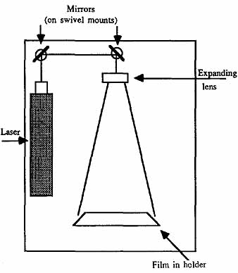
ill. 18-13. Top view of the laser, mirrors, lens, and film holder for
a portable transmission hologram viewing table.
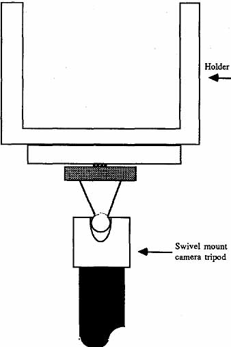
ill. 18-14. A swivel mount from a portable camera tripod can be used to
position the film holder at angle to a laser or white light source.
Table 18-6. Portable Hologram Viewing Table Parts List
- 1 18-by-24-inch piece of ¼-inch Masonite or ¾-inch plywood
- 1 Laser
- 2 Mirrors on swivel mounts (see Section 7)
- 1-2 8 to 10 mm diameter bi-concave lenses, in mounts (see Section 7)
- 1 Film holder, with swivel mount
The film holder is designed so that it can be tilted in relation to the laser beam. A ball-and-socket joint from a low-cost portable tripod can be used to adjust the angle. Simply loosen the knob and tilt the film holder into the position you want. Lock the knob and the holder stays in place.
Although some people might want to see the inner workings of your holographic setup, you’ll probably want to enclose it to block stray light. A frame made of plastic or metal can be constructed and placed over the table. Alternatively, you can position the table behind a partition and expose just the holographic film for viewing. Use pieces of black velvet or other material as drapes. This technique can be used when your holograms are on display at the fair, photo show, or museum.
An even simpler arrangement can be built for reflection holograms. The laser isn't necessary, nor are the beam-expanding optics. You need a fairly bright point source of light, positioned above the hologram. The hologram should be mounted in a tiltable holder, as illustrated in ill. 18-14, to allow you to set the proper angle of view. You can also motorize the holder so that the angle of the hologram shifts slowly, revealing its 3-D nature. An animation motor (designed for point-of-sale promotional signs), hooked up to a cam for the forward and backward motion, should do nicely.
Manual and Automatic Beam Shutter
Using a card as a shutter has its disadvantages: it’s clumsy to use and you could actually disturb the table as you lift it out of the sand. Just being close to the sand table during the exposure can cause unwanted air movements that can upset the optics, beam, and film. And if you use a high-powered 8 to 10 mW He-Ne for your holograms, the light might be so strong that you only need exposure times of less than 1 second. With short exposure times come inaccuracy: it's hard to manually control the shutter card with accuracy of better than ½ second.
One way of providing more accurate shutter control is to use the shutter mechanism on a discarded camera. Use an old camera with a leaf-type shutter—the kind resembling an iris. Don’t use a focal plane shutter such as those used in most 35 mm or digital SLRs. You can find old cameras at flea marts and garage sales.
Inspect the camera to make sure that the shutter is still working, then take the camera home and dismantle it. Remove the shutter and mount it on a stand where you can easily reach the shutter speed control, release, and cocking mechanism (some shutters are self-cocking).
With the shutter, you can set the desired short-exposure time by dialing it in on the speed control knob, cocking the shutter, and pushing the shutter release. Most of the old shutters open and close with an unmistakable clang that can vibrate through the table and disturb the optics and film. Therefore, for best results, locate the laser and shutter off the table. As long as the laser is on a fairly sturdy mount, any slight movement won't affect the hologram (assuming the laser is well made and doesn’t loose coherency when vibrated; a check with the Michelson interferometer can visually show you how well the laser maintains coherency).
Old camera shutters usually don’t have settings longer than one second. For time exposures, you place the speed control ring in “bulb” position and manually control the duration that the shutter is open. Use a cable release and a darkroom timer to manually control the shutter.
A fully electronic shutter system is shown in ill. 18-15. Here, a 12-volt solenoid is mounted on a piece of ¼-inch thick acrylic plastic. The plunger of the solenoid connects to the shutter plate as well as a spring. When the solenoid isn't energized, the shutter is at rest and blocks the beam. Energize the solenoid and the shutter moves, unblocking the beam. The finished solenoid shutter is shown in the photo in ill. 18-16. A parts list for the solenoid shutter is provided in TABLE 18-7.
A photographic light meter can be used to test the output of a laser or to make sure that the beam ratios are correct for a given holographic setup. Best results are obtained using a well-made meter with a white diffusing filter placed over the sensing element. The filter prevents the laser light from forcing the sensor into non-linear operation. The filter isn’t strictly needed when measuring expanded laser light.
You can make your own power/light meter using an ordinary solar cell and a volt- ohmmeter (VOM). Connect the solar cell to the voltmeter as shown in Section 4. Place a small piece of white diffusion over the cell. To use the meter, dial the VOM to the mV range, and position the cell in the path of the beam.
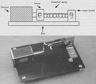
ill. 18-15. Layout for the solenoid shutter. ill. 18.16. The completed
solenoid shutter.
POWER/LIGHT METER
Table 18-7. Solenoid Shutter Parts List
- 1 12 Vdc solenoid, with mounting bolts or screws
- 1 ½-inch-long expanded spring (length when relaxed)
- 2 1-by-½-inch corner angle irons
- 1 ½-by-¾-inch plastic (for shutter)
- 1 6/32-by-1/2-inch bolt, nut, washer
These past two sections have only lightly covered the art and science of holography, leaving many topics untouched. If you would like to learn more about holography, refer to Section B for a list of selected books on the subject. One in particular, Holography Handbook (Unterseher, Hansen, and Schlesinger) offers an excellent tutorial in making many types of basic and advanced holograms.