UNREGULATED POWER SUPPLIES
Two different types of unregulated power supplies are shown here.
In Fig. A, a full-wave bridge rectifier is shown using four silicon diodes, each diode having a 100-volt peak-inverse rating. There are four different ways that the circuit in Fig. A may be connected.
Using primary terminals 1 and 3 of the transformer with the secondary terminals connected in parallel and the choke terminals connected in parallel, the diode rating must be 1.5 amperes, and the resistance value is 70 ohms. Under these conditions, the output is 13 volts at 2.5 amperes with a 17 % regulation.
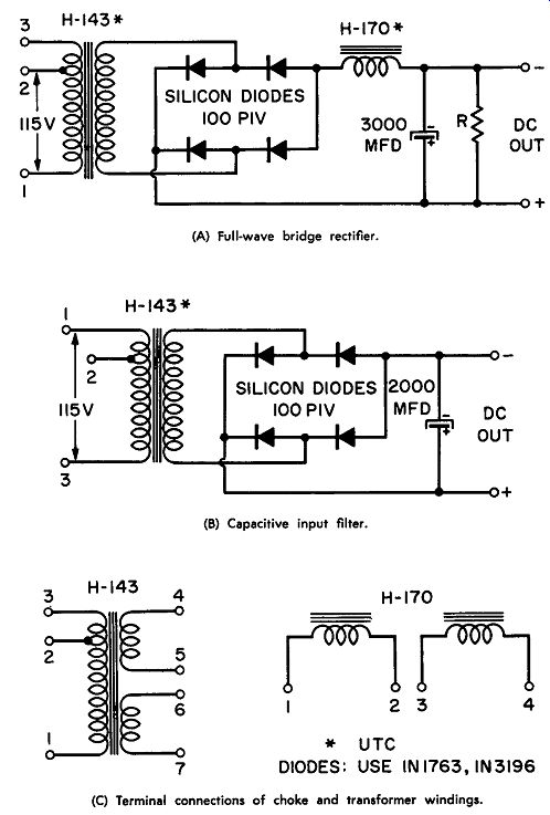
--------- Unregulated power supplies.
(A) Full-wave bridge rectifier.
(B) Capacitive input filter.
(C) Terminal connections of choke and transformer windings.
With primary terminals 1 and 2 being used, and the secondary terminals of the transformer as well as the choke terminals connected in parallel, the diodes carry 1.5 amperes, and the resistance should now be 60 ohms. Under these conditions, the output is 16.5 volts at 2.5 ampere with a 12% regulation.
Using terminals 1 and 3 of the primary, with the secondary terminals connected in series and the choke terminals connected in series, each diode will conduct 0.75 ampere, and the resistance value is now 300 ohms. The output is 27 .5 volts at 1.25 amperes with a 13 % regulation.
Using primary terminals 1 and 2, with the secondary terminals in series and the choke terminals in series, the diodes carry 0.75 ampere, and the resistance value is now 250 ohms. The output is 34.5 volts at 1.25 amperes with a 12 % regulation.
Fig. B shows the same transformer and diodes, but with a capacitive input filter without a choke. Using primary terminals 1 and 3 with the secondary terminals connected in parallel, the diode will carry 1.5 amperes and the output is 19.6 volts at 2 amperes with a 30% regulation.
Using primary terminals 1 and 2, with the secondary terminals connected in parallel, the diode current is 1.5 amperes but the out put is 25.5 volts at 2 amperes with a 26% regulation.
Using primary terminals 1 and 3 with the secondary terminals connected in series, each diode carries 0.75 ampere, and the output is 42 volts at 1 ampere with a 24% regulation.
Using primary terminals 1 and 2 with the secondary terminals connected in series, each diode carries 0.75 ampere, and the output voltage is 53 volts at 1 ampere with a 20% regulation.
Fig. C shows the terminal connections of the transformer windings and the choke windings.
BASIC LOW-VOLTAGE SUPPLIES
Three basic low-voltage power supplies are shown. Fig. A shows a half-wave supply, Fig. B shows a full-wave supply, and Fig. C shows a voltage doubler.
Fig. A is a simple half-wave circuit. With a power transformer with a 2-to-1 step-up operating from a 117-volt line, this circuit produces from 270 to 290 volts DC.
The full-wave circuit shown in Fig. B is essentially two of the circuits shown in Fig. A; the circuit can deliver an output voltage of 280 to 310 volts, depending on the current drain required of the circuit.
----- Basic low-voltage supplies. (A) Half-wave power supply.
(B) Full-wave power supply.
(C) Full-wave voltage doubler.
For both circuits the suggested rectifiers are the F-8, which has a maximum peak-inverse voltage of 800, a maximum rms voltage of 560, and a maximum d-c current of 750 ma. The ST18 or the 80H may also be used. All of these rectifiers have the same ratings, but they are different physical types.
Fig. C shows a voltage doubler operating with a 1-to-1 transformer and producing from 270 to 290 volts DC. Suggested rectifiers are the 40H, the F-4, or the ST14. These rectifiers have a maximum peak inverse voltage of 400 volts, a maximum rms voltage of 280, and a maximum d-c current of 750 ma.
REGULATED POWER SUPPLY
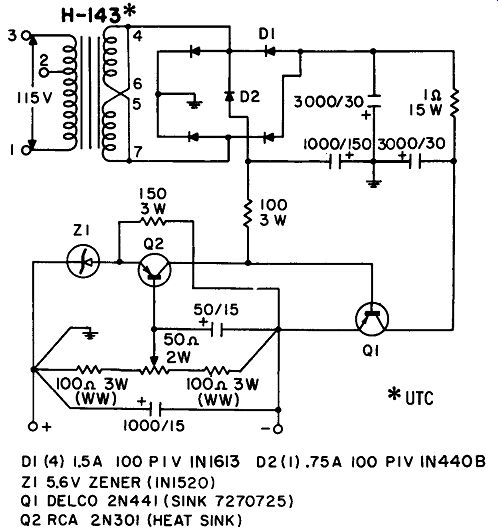
This circuit shows a regulated power supply, with a 115-volt input to terminals 1 and 3 of the transformer primary. The secondary windings are connected in parallel and feed a bridge rectifier with a capacitive filter.
----------- Regulated power supply.
A regulator is used to correct the line-voltage variations or load variations. The output voltage can be varied from 11.5 to 12.5 volts DC by means of the control in the base of transistor 02. Output current can vary from O to 2 amperes; there is 5-millivolt ripple in the output. The regulation for a line voltage from 105 to 125 volts is 3.5%.
REGULATED SUPPLY
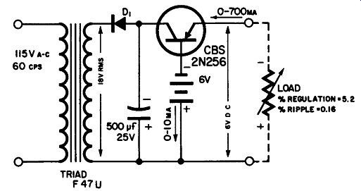
This is a simple regulated power supply operating from 115 volts ac and using a single power transistor. The rectifier diode (D1) is two 500-ma selenium rectifiers in parallel, or the equivalent. This is a series type of regulated power supply where the output voltage re mains constant for wide variations of the inputs. The secondary voltage should never exceed 25 volts rms.
As shown, a 6-volt battery is used for reference; however, the battery may be replaced by a zener diode (National Type A5B or the equivalent). It is also possible to obtain other values of output voltage than 6 volts, as shown in the schematic, by using different reference voltages or a different zener diode. The output voltage of this circuit is less than ½ volt higher than the reference source.
As shown, the regulation is 5.2% with a 0.16% ripple, from 0 to 700 ma.
--------------- Regulated power supply.
REGULATED POWER SUPPLY
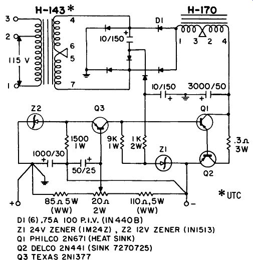
This circuit shows a regulated power supply, with a 115-volt input to terminals 1 and 2 of the transformer. Output is variable from 26 to 30 volts DC; for the adjustment use the control in the base of transistor Q3.
After it is filtered, the output from the bridge rectifier is fed to the regulation circuit which compares the output voltage to a reference voltage. The positive end of the output is grounded, and the negative output voltage can be varied from 26 to 30 volts. The ripple in the output is 0.12 millivolt. Regulation with a line voltage variation from 105 to 125 volts is 0.1 %.
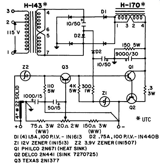
------- Regulated power supply.
REGULATED POWER SUPPLY
This circuit shows a regulated power supply fed from a 115-volt line; the output is from 11 to 13 volts DC (the positive end is grounded) with a current of 0 to 2 amperes.
A bridge rectifier is used with a choke and a filter capacitor. The regulator circuit compares the output voltage with the reference voltage and compensates for any variations of load or line. There is a ripple of 0.35 millivolt. With a line voltage variation of 105 to 125 volts, the regulation is 0.1 % . Note the special nature of the ground on the positive side; it is 4 inches of No. 22 solid wire.
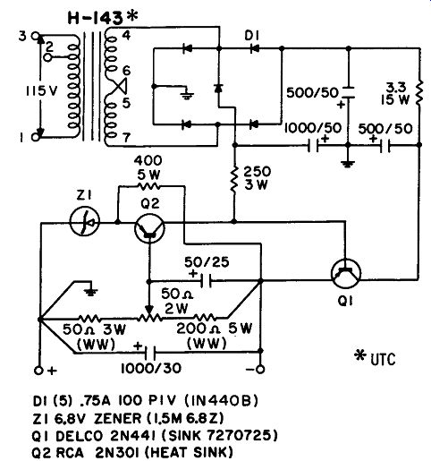
--------------- Regulated power supply.
REGULATED POWER SUPPLY
This circuit shows a regulated power supply with an output of 27 to 29 volts DC at up to 1 ampere. Line-voltage input is between point 1 and point 3 of the transformer; the secondary is connected in series. A capacitive filter is used. The regulating circuit compares a reference voltage to the output and provides for proper compensation to keep the voltage output constant.
The ripple in the output is 1.5 millivolts; there is a 1% regulation for variations in the line input from 105 to 125 volts. An adjustment is provided in the base of transistor Q2 to adjust for the desired power output.

---------------- Regulated power supply.
12-VOLT REGULATED SUPPLY
This circuit shows a 12-volt regulated power supply using transistor types 2N1274 and Tl3027. The 2N1274 is a germanium small signal transistor, while the T13027 is a power transistor.
In this circuit the 1N759 is a reference diode connected to the base of the 2Nl274. The 2N1274, connected by a Darlington connection to the T13027, acts as a series regulator. This regulator is extremely sensitive to current changes in the reference diode.
The change in output voltage from no-load to a full 1.5-ampere load is 0.4 volt, while the ripple at full load is 30 millivolts. The change in the output voltage with a 10% change in the line voltage from the normal 11 7 volts is very small.
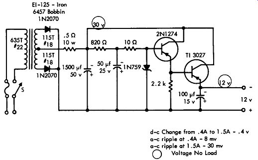
------ 12-volt regulated supply.
450/800-VOLT SUPPLY
This is a dual-voltage power supply that provides two voltage outputs; one output is 800 volts at 175 ma with a 1 % ripple at a 16% load regulation, such as is required for a final radio-frequency power amplifier, and a second output is 450 volts at 25 ma with a 0.02 % ripple, such as is required for a preamplifier or an oscillator circuit.
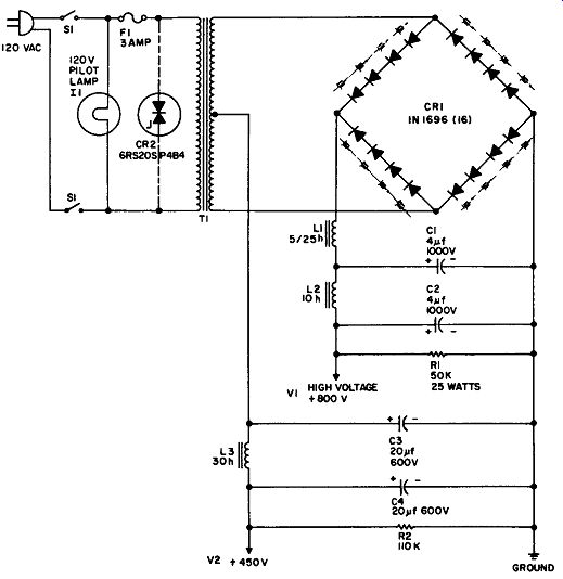
----------- 450/800-volt supply.
C1, C2-4 mfd, 1000 volt capacitor (Cornell Dubilier 10040)
C3, C4-20 mfd, 600 volt electrolytic capacitor
CR1-16 G-E type 1Nl696 silicon rectifier diodes connected in groups of four
CR2-G-E type 6RS20SP4B4
Thyrector diode (optional transient voltage suppressor)
F1-3 AGC fuse, 3 amps
L1-120 volt, 6 watt pilot lamp
L1-5/25 henry choke, 175 ma (UTC S-30, or equivalent)
L2 - 10 henry choke, 175 ma (UTC S-29, or equivalent)
L3 -30 henry choke, 25 ma (UTC S-25, or equivalent)
R1-50K, 25 watt resistor
R2- 110K, 4 watt resistor (2-220K, 2 watt resistors in parallel)
S1-DPST switch
T1-200 ma transformer: primary, 120 volt AC, 60 cps; secondary, 800 volt (Stancor PC-8412, or equivalent)
There is a common ground for both outputs. To provide a variable d-c voltage output, an adjustable line transformer can be used before the step-up transformer.
As shown, the transformer is center-tapped, and a bridge rectifier with four silicon diodes in each leg is used for the high-voltage output. The same transformer is used with the rectifier diodes in the two right-hand legs to provide a full-wave rectifier for the lower voltage power supply. The high-voltage power supply uses a choke input filter, while the low-voltage power supply uses a capacitor-input filter. If desired, the 450-volt supply may be reduced to 375 volts by removing capacitor C3 from the circuit.
A transient-suppressor diode (CR-2) is used to protect the silicon rectifiers against the voltage transients; a pilot lamp is also shown, and it is suggested as a safety precaution, since in the absence of filaments it is not always possible to tell from inspection when the power supply is on.
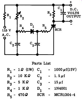
------------- Transformerless d-c power supply.
TRANSFORMERLESS D-C POWER SUPPLY
This circuit shows a transformerless d-c power supply suitable for use in lightweight equipment; a single controlled rectifier is used without a unijunction transistor. Alternating current from the line source is applied to the circuit as shown. There is a phase delay because of the two circuits, one of which is resistor R4 and capacitor C2, while the other is resistor R5 and capacitor C3. The rectifier diode is used to prevent reverse current flow to the gate.
As resistor R2 is varied, the voltage which is phase-shifted to the gate of the controlled rectifier is changed; hence, the on time of the controlled rectifier can be varied. Capacitor C1 is the output filter capacitor. At 100 ma of output current, this circuit provides 10 volts output; at 200 ma of output current the output voltage drops to approximately 6 volts.
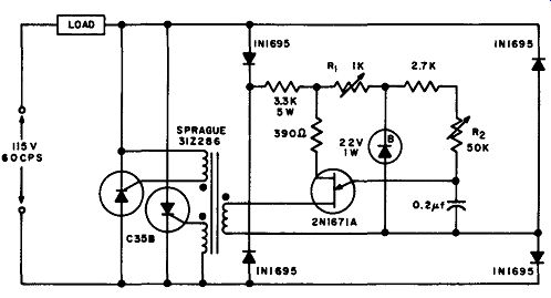
--------------- Regulated a-c power supply.
REGULATED A-C POWER SUPPLY
This circuit shows a regulator for a-c power, and it performs the same function as a constant-voltage transformer at considerably less cost and in much less space. The line voltage is in series with the load and the regulator, as shown. Resistor R1 is used for adjustment to allow the peak voltage point to increase when the line voltage is increased, thereby retarding the firing angle of the controlled rectifiers and causing a reduction in the voltage applied to the load.
Resistor R2 is used to adjust the circuit for any desired output voltage. Current output is determined by the rating of the controlled rectifiers, and for the rectifiers shown in the circuit, the current can be as much as 32 amperes. Functionally, a bridge rectifier is used to provide d-c power for unijunction-transistor 2N1671A, whose output is fed to the gate leads of the controlled rectifiers.
TRANSFORMERLESS D-C POWER SUPPLY
This circuit shows a lightweight power supply designed to pro duce a 10-volt output at 100 ma from a standard line voltage source.
A controlled rectifier and unijunction transistor are used. As shown in the circuit, resistors R2 and Ra, as well as capacitor C2, are used to make up the time delay, which is a part of the unijunction transistor circuit; this time delay determines the unijunction switching.
If the value of resistor R3 is increased, the output voltage of the circuit decreases. The trigger pulses from the unijunction transistor are applied to the gate of the controlled rectifier. The rectifier is then turned off and on by the unijunction transistor, and the chopped ac is filtered by means of capacitor C1. When this capacitor is 1000 microfarads, as shown in the circuit, a 2.5 % ripple voltage will appear across the load resistance at the designed center value of 10 volts and 100 milliamperes. Total power-supply efficiency is about 77%.
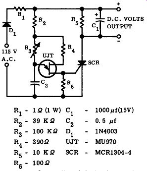
------------- Transformerless d-c power supply.
----------------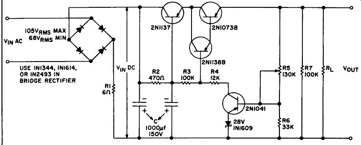
REGULATED POWER SUPPLY
This circuit shows a regulated power supply using rectifier types 1N1344, 1N1614, or 1N2493.
A-c input to the bridge rectifier is 105 volts maximum and 68 volts minimum; both of these voltages are rms values. Output is 90 volts at a current of up to 700 milliamperes. A transistor regulator follows the bridge rectifier. This is a conventional rectifier where the 2N1041 compares a portion of the output voltage to the voltage developed across the 1N1609 zener diode; this voltage, by means of the 2Nl 138B transistor, is used to control the series resistance of the transistors through which the output current flows.
BASIC HIGH-VOLTAGE POWER SUPPLIES
Three basic high-voltage power supplies are shown. Fig. A shows a half-wave 1000-volt supply using the S5521 rectifier whose peak inverse voltage is 3000 volts, maximum rms voltage is 2100, and maximum d-c current is 150 ma.
A full-wave 5000-volt supply using a bridge rectifier is shown in Fig. B. The suggested silicon diode is the S-5531 which has a maxi mum peak-inverse voltage of 10,000 volts, a maximum rms value of 7000 volts, and a maximum d-c current of 25 ma.
Fig. C shows a three-phase 7500-volt supply with a full-wave rectifier in each leg. The suggested rectifier is the same as the one used in the circuit in Fig. B.
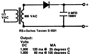
-------------- Basic high-voltage power supplies.
--------------
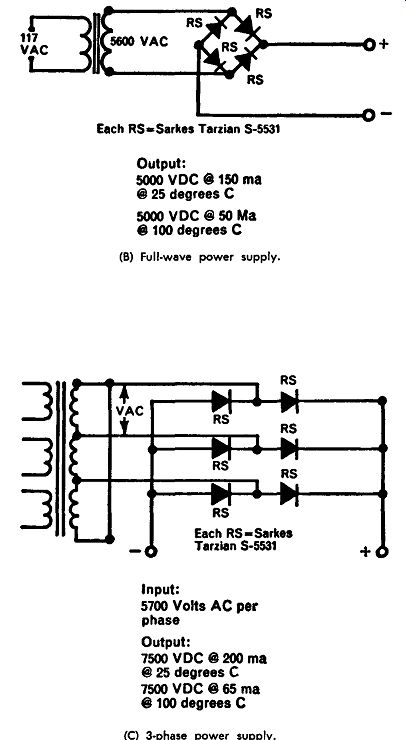
(A) Half-wave power supply. (B) Full-wave power supply. (C) 3-phase power supply.