Five linear ranges to 10,000 µF
BY THOMAS McGAHEE
WHEN a capacitor is connected to a constant-voltage source through a resistor, the charge on the capacitor increases exponentially. If the source supplies a constant current, however, the charge on the capacitor increases linearly. This linear charging principle is used here in the design of a capacitance meter which will measure values outside the range of most such meters. By using a constant-current source, the meter determines the time it takes to match the charge on the unknown capacitor to a known reference voltage. The meter has five full-scale ranges of 1, 10, 100, 1000, and 10,000 µF. On the 1-µF scale, values as small as 0.01 µF can be read easily.
How It Works. As shown in Fig. 1, D1, D2, R6, Q1 and one of the resistors (R1 through R5) selected by S1A provide five decades of constant current.
With S2 in the position shown in Fig. 1, this current is shunted to ground via S2A. When S2 is placed in its alternate position, the constant current will be pumped into the unknown capacitor connected across BP1 and BP2, forcing it to charge in a linear fashion.
Op amp IC1 is connected as a comparator, with its noninverting (+) input connected to R8, which determines the reference voltage. When the voltage developed across the unknown capacitor, connected to the inverting input (-) of IC1, becomes a few millivolts higher than the preset reference voltage, the comparator output will switch from +12 volts to-12 volts.
The output of the comparator drives a constant-current source consisting of D3, D4, D5, R10, R11, and Q2. When S2A was switched to ground, so was S2B. This action shorts across storage capacitor C1, therefore the voltage across this capacitor is zero.
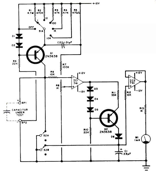
Fig. 1. The meter determines the time it takes to match the charge in
capacitor under test to known ref. voltage.
PARTS LIST
BP1, BP2-Five-way binding posts (one red, one black)
C1, C4-22-µF, 35-volt electrolytic capacitor C2-0.01-µF ceramic disc capacitor C3-220-µF, 35-volt electrolytic capacitor DI to D6-IN914 diode D7, D8-50-volt, 500-mA silicon rectifier D9, D10-12-volt zener diode ICI, IC2-741 mini-DIP case MI-0-I-mA meter (Radio Shack 22-052 or equiv.) Q1, Q2-2N 3638 transistor R1-4.7-megohm, 1/2-w 5% resistor R2-470,000-ohm, 1/2-w 5% resistor R3-47,000-ohm, 1/2-w 5% resistor R4-4700-ohm, 1/2-w 5% resistor R5-470-ohm, 1/2-w 5% resistor R6, R10-22,000-ohm, 1/2-w resistor R7-100,000-ohm 1/2-w resistor R8-1000-ohm, pc-type trimmer potentiometer R9, R12-10,000-ohm, 1/2-w resistor R 11-33,000-ohm, 1/2-w resistor R13-1000-ohm,1/2-w resistor R14-560-ohm, 1/2-w resistor R15-470-ohm, 1/2-w resistor S1--Dp 6-pos. rotary switch (Radio Shack 275-1386 or equiv.) S2-Dpst or dpdt pushbutton or rocker switch TI-Transformer, secondary 12-V, 300 mA (Radio Shack 273-1385 or equiv.)
Misc.-Suitable enclosure (Radio Shack 270-627 or equiv.), line cord, insulated wire, spacers, rubber feet (4).
When S2 is opened, the constant current flowing into C1 causes the voltage across it to rise linearly. When the voltage across the capacitor under test causes the comparator to switch, diode D6 becomes reverse biased, preventing C1 from charging any more. Since C1 only charges until the comparator switches, the voltage generated across it is directly proportional to the capacitance value of the unknown capacitor.
To prevent C1 from discharging while measuring its voltage, a high-impedance buffer, formed by IC2, is used. While this buffer draws very little current, it does draw some, and this results in a very slow downward drift of the meter-but this drift is actually too slow to cause any problems. Resistor R13 and meter M1 make up a simple voltmeter readout of approximately 1 volt full scale. If desired, an external voltmeter can be used as long as it has a full-scale range of less than 8 volts. (If you use such an external meter, set R8 on the 1-µF range, so that a known 1-µF capacitor indicates 1 volt.) Capacitor C2 is used to prevent oscillation of the Q1 constant-current source, while R9 and R12 protect the op amps in case the power is turned off while the test capacitor and C1 are charged, otherwise they might discharge via the op amps, causing damage.
The accuracy of the capacitance meter depends on two factors; the power supply whose circuit is shown in Fig. 2, can supply sufficient current to power the meter.
Construction. The circuit can be built on the pc board whose foil pattern is shown in Fig. 3, along with the component installation on the non-foil side of the board. Be sure to observe the polarity of the two electrolytic capacitors and the various diodes.
The IC's are identified by a notch code.
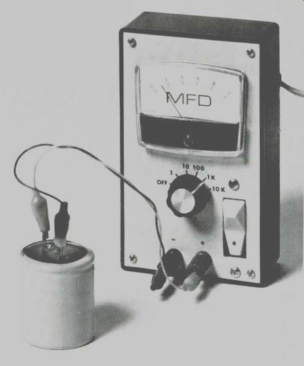
The prototype was assembled in a 6 1/4" by 3 3/4" by 2" plastic box having a metal cover. The cover was drilled to accept Ml, range switch SI, switch S2, and the two binding posts (BP1, BP2). Note that a red binding post was used for BP1 as this side is to be connected to the positive lead of the capacitor under test. The line cord exits through a small hole in the side of the plastic box.
Meter M1 is linearly calibrated to 1 mA full scale. Carefully open up the meter and using press-on type, or other printing medium, mark the scale "MFD" or "µF."
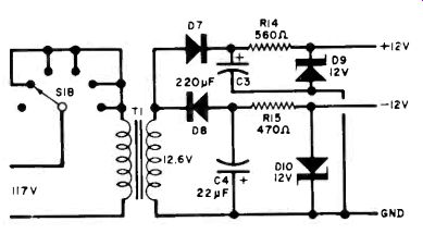
Fig. 2. Power supply delivers sufficinet current for meter.
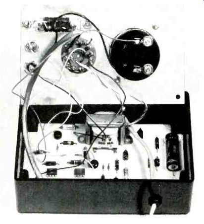
----Photo shows prototype of assembled unit.
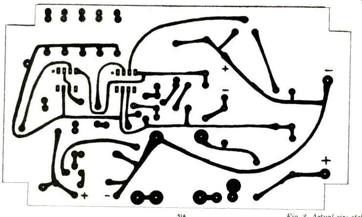
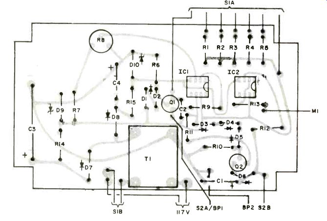
Fig. 3. Actual-size etching and drilling guide is above, component layout
at left.
The accuracy of the capacitance meter depends on two factors; the basic accuracy of the meter movement used and the accuracy of resistors R1 through R5. In most cases, the meter accuracy will be 3%, and experience has shown that, with 5% tolerance resistors, the overall accuracy is about 3%. Although this may sound strange, it is due to the fact that most 5% resistors made by the same company tend to be off tolerance by the same percentage, thus reducing the effective percent error between the resistors. Using 10% resistors yields about 6% accuracy.
Calibration. Before applying power to the capacitance meter, use a small screwdriver to set the meter pointer exactly to the zero mark.
Select a capacitor between 0.5 and 1.0 µF at 5% or better. This will be the "calibration standard." Connect this capacitor between BP1 and BP2 (positive side to BP1). Set range switch S1 to the "1" position (meter indicates 1-µF full scale). Operate S2 to remove the ground lead from the two circuits (Q1 collector and C1). The meter should start upscale and stop at some value. Reversing S2 should cause the meter to drop to zero volts. Flip S2 again and note the upscale value of the meter. Alternately flip S2 and adjust R8 until the meter indicates the exact value of the 5% calibration capacitor. The one calibration will suffice for all the other ranges.