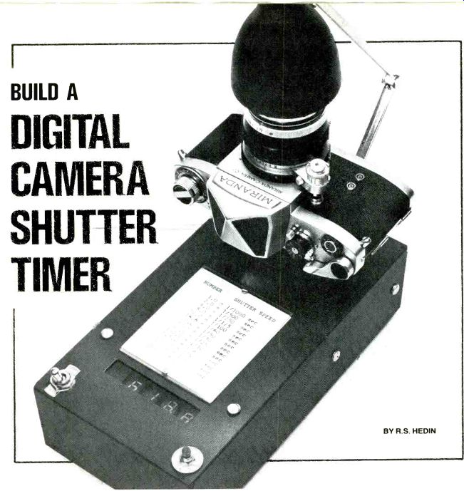
by R.S. HEDIN
Low cost digital timer provides accurate check of camera shutter speeds from 1/1000th of a second to 1 second.
HAVE YOU ever wondered why a camera whose diaphragm opening and shutter-speed setting are adjusted perfectly according to an exposure meter should regularly produce overexposed or underexposed negatives or prints? Too often, the cause is a shutter speed that deviates too much from the camera's speed markings.
Now you can check your camera's actual shutter speed by building the electronic shutter tester presented here. If the camera displays a gross speed inaccuracy, you'll know that you must compensate for it by modifying the camera's control adjustments (say, an f stop greater or smaller than the exposure meter's indication) or having the camera serviced professionally.
With your own shutter tester, you can test your camera at any time you feel it needs adjustment. The shutter tester described here uses digital circuits and has six decades of display to give a high order of accuracy.
===========
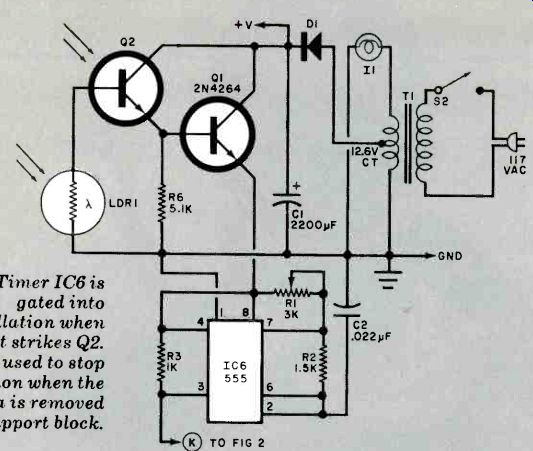
Fig. 1. Timer 106 is gated into oscillation when light strikes Q2.
LDR1 is used to atop operation when the camera is removed from support block.
PARTS LIST
C1-2200-µF, 16-volt electrolytic capacitor
C2-0.022-µF
Mylar capacitor DISI through DISS-'7a" common-cathode, seven-segment LED display (DL-704 or similar)
D1-100-volt, I-ampere silicon rectifier diode
I_1--12-volt high-intensity lamp with arm and reflector (see text)
IC1 through
IC5-4033A CMOS decade counter
IC6-555 timer
LDR 1-Light-dependent resistor (Vactee No. VT-214 or Clairex CL-903)
Q1-2N4264 transistor
Q2-FPT-100 phototransistor
R1-3000-ohm trimmer potentiometer
The following resistors t/4 watt, 10% tolerance: R2-1500 ohms R3, R4, R51000 ohms R6-5100 ohms
S1-Normally open, momentary-action spst pushbutton switch
S2-Spst toggle switch
T1-12-volt, 1.2-ampere transformer (see text)
Misc.-Printed circuit or perforated board; 16-pin DIP sockets (5); 14-pin DIP sockets (5); 8-pin DIP socket; chassis with cover (9" x 5" x 2 1/2' ); line cord; pine block (3 .25 x 1 3/4" x 1 3/4"); soft vinyl sheet; rubber feet (4); contact cement; machine hardware and spacers; hookup wire: solder; etc.
============
About the Circuit. The sensor/control circuit for the tester is shown in Fig. 1, while the counting circuit is shown in Fig. 2. The two circuits are coupled together via the +V and GND buses and the points marked K going to each other.
When light strikes phototransistor Q2 and not LDR1 in Fig. 1, the Darlington circuit made up of Q2 and ordinary transistor Q1 triggers on and supplies current to timer 106. This causes the timer IC to generate pulses at a frequency of 10,000 Hz. (Potentiometer R1 is provided for adjusting the operating frequency of the oscillator to exactly 10,000 Hz.) If at any time light strikes LDR1, the resistance in the base circuit of Q2 drops to a low enough value to cause the Darlington circuit to cut off. This, in turn, turns off the timer circuit. Under normal operating conditions, no light will fall on either Q2 or LDR1 initially. After pressing reset switch S1 (Fig. 2), light is allowed to reach only Q2. This allows the timer circuit to generate a 10,000-Hz pulse output that is counted by the totalizer circuit shown in Fig. 2. The displays continue to count upward until the light to 02 is interrupted or light falls on LDR1. At this time, the displays "freeze" to indicate the total number of pulses counted. When the tester is used with a camera, the camera's body covers LDR1 to exclude all light and the shutter/lens mechanism is positioned directly above Q2, in line with a high-intensity light source. Switch Si is momentarily depressed to reset the counters to zero.
Then, when the shutter is tripped, the system counts the number of pulses generated between the opening and closing of the shutter.
The counting circuit shown in Fig. 2 consists of five decade-counter IC's (IC1 through /C5) and their companion seven-segment displays (DISC through DIS5). Note that DIS2 is the only display whose decimal point is active. This decimal point comes on whenever the tester is powered. Note also that the decade counters are wired to suppress the zeroes to the left of the decimal point.
Since the display indicates the number of pulses counted during a discrete interval of time, it does not indicate time.
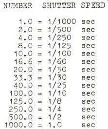
To obtain the time indicated by the number in the display, you must divide that number by 1000. Hence, displays of 1.0, 8.0, 16.6, and 33.3 translate to 0.001, 0.008, 0.0166; and 0.0333 second or, in photography terminology, 1/1000, 1/125, 1/60, and 1/30 second, respectively. (It is a good idea to make up a table of conversions that can be affixed to the completed project, as shown in the lead photo.) The power supply for the tester is line operated. Dc power for the system is obtained from a conventional rectifier diode/filter-capacitor (D1/C1) setup that is driven from the center tap of transformer T1. This circuit assumes that high-intensity lamp /1 is an integral part of the system. If you prefer, you can use a separate line-powered high-intensity lamp and substitute a 6.3-volt transformer for T1.
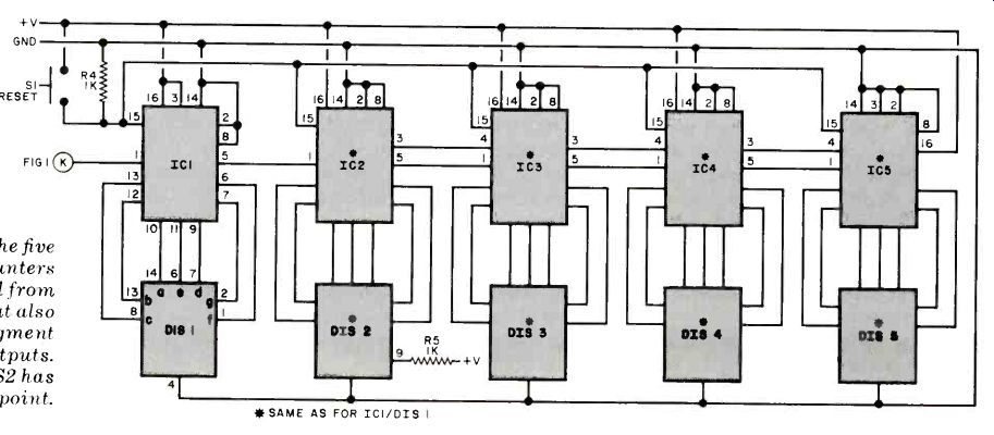
Fig. 2. The five decade counters are formed from IC's that also include
7-segment decoded outputs.
Note that DIS2 has the decimal point.
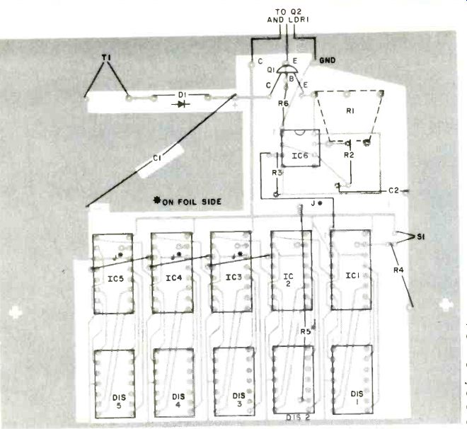
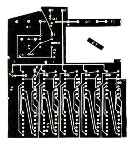
Fig. 3. Foil pattern and component installation. Pin 15 of IC1 through
IC5 are connected together by a common jumper on the foil side of the
board. Note that R5 and the other jumpers are also located on the foil
side.
CONVERSION TABLE
Construction. The entire circuit, except T1 and the two switches and Q2 and LDR1, can be assembled on a single printed circuit board, the etching and drilling and component-placement guides for which are shown in Fig. 3. Alternatively, you can assemble the circuit on perforated board, using appropriate solder hardware. In either case, the use of sockets for the IC's and displays is recommended.
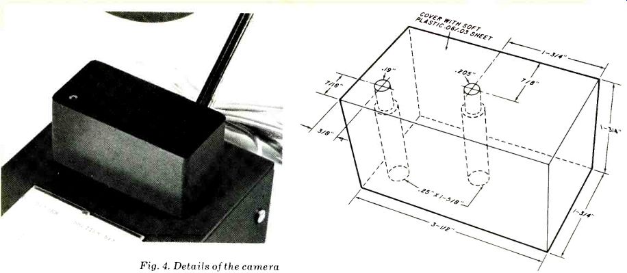
Fig. 4. Details of the camera mounting block. The two photosensitive
devices (Q2 and LDR1) are mounted close to the upper surface of the
block.
Install the components on the circuit board as shown in the component-placement guide, taking care to properly orient them. Note here that the four jumper wires labeled J and R5 mount on the foil side of the board. To avoid the possibility of short-circuiting the board, be sure to use insulated sleeving on the resistor leads and wire jumpers.
Phototransistor Q2 and light-dependent resistor LDR1 mount in a block of pine as shown in Fig. 4. The holes in which these two components mount must be stepped as indicated to permit easy routing of the hookup wires that interconnect them with the rest of the circuit. Note that LDR1 mounts in the hole at the lower left corner and Q2 mounts in the hole in the center of the block.
Before you mount Q2 and LDR1 in the block of wood, apply a coat or two of flat black paint to all exterior surfaces of the block. Allow the paint to completely dry, and then mount the components in their respective holes, fixing them in place by force fitting. (If the fit is too snug, very carefully ream out the holes; if it is too loose, sparingly apply a drop or two of clear plastic cement to the component edges. Both components mount flush with the top surface of the block. When this is done, use contact cement to fasten a thin sheet of soft matte black vinyl to the top of the block after first punching holes in it for Q2 and LDR1.
A 9"D x 5"W x 2 1/2"H (22.9 x 12.7 x 6.4 cm) metal box comfortably accommodates the circuit board assembly, power transformer and its line cord, and switches. The case must be machined to provide a 25/s" x 1/2" (6.7 x 1.3 cm) window for the displays; mounting holes for the switches, transformer, and wood block; and access holes for the line cord and leads from Q2 and LDR1. Once the case has been machined, spray two or three coats of matte black paint over all exterior surfaces. When the paint has dried, cement a red filter over the window from the inside. Then mount the wood block with screws, followed by T1, S1, and S2. Next, interconnect the switches, transformer, line cord (passed through the case via a rubber grommet), LDR, and phototransistor. Finally, mount the circuit board assembly in place with machine hardware and spacers, making sure its displays are properly oriented behind the filter.
Checkout and Use. Place a piece of black plastic tape over LORI, plug the line cord into a convenient ac outlet, and turn on the tester's power. Now, using an oscilloscope or a frequency counter, adjust potentiometer R1 for an exact 10,000-Hz output from timer 106. This completes calibration. Remove the tape from LDR1.
Open the back of the camera you wish to test and place it on the wood block so that the lens opening is directly over Q2.
Make sure that the camera body covers LDR1. Then set the camera's lens diaphragm for maximum opening, set the shutter speed, and cock the shutter. Depress reset switch S1 so that all displays read zero. Trip the camera shutter. The displays should rapidly count up and freeze at a number that is the shutter speed in thousandths of a second.
Check each shutter speed at least three times, resetting the display at the start of each test. The shutter can be checked with or without the lens on the camera. With the lens on the camera it is more critical that the lens be placed directly over Q2 as there is a smaller spot of light. In all tests keep the light about 6 inches above the platform.
Do not be disappointed if your shutter speed is not close to its camera setting.
Up to 1/500 of a second, the allowable error may be as great as ±25%; at higher settings, the allowable error might increase to ±35%. These figures would depend on the tolerance of the film used, of course.
With the aid of the camera shutter timer described here, you can eliminate some of the uncertainties you have about the accuracy of your camera's mechanism. Additionally, it can tell you why your latest batch of photos did not turn out as they should have.
-------- Underside of timer reveals pc board and transformer
mounting.
Also see: Talk Over A Sunbeam With A "Photophone"