Sounds an alarm after preset time when refrigerator door is left open.
REFRIGERATORS are among the hungriest of household appliances in terms of electrical power consumption. Every time a refrigerator door is opened, cold air spills out and the warm air that replaces it must be cooled.
Needless to say, it pays in dollars and cents to limit the time the door is open to as brief a period as possible. The low-cost Fridge Alarm described here maybe just what you need to limit the time you study the contents of your refrigerator or your child forgets to close the door.
The Fridge Alarm is a photoelectric device that is activated as soon as the door opens and the refrigerator's light goes on. It sounds an insistent two-tone signal if the door remains open past a given number of seconds.
About the Circuit. As shown in Fig. 1, when light strikes its photosensitive surface, Q1 triggers into conduction and causes 02 to saturate. This places pin 1 of IC1 close to ground potential and allows the timer to start operating (Fig. 2). Since the voltage across C1 is initially zero, IC1 is triggered into immediate operation. Timing is controlled by R8, R1, and C1.
During the timing sequence, the output of IC1 at pin 3 remains high (almost at Vcc) and keeps 1C2 and 1C3 cut off, since pin 1 of each of these integrated circuits is connected to this line.
Most electrolytic and many aluminum capacitors can have sizable leakage currents. Hence, they should not be used in timing circuits. To avoid this problem, C1 should be a tantalum capacitor. Using the time constants shown, R8 can be set for periods of from 4 to 17 seconds. (This range was selected because 8 seconds is about the mean time for access to a refrigerator.) Because C1 discharges through D1 and the 15,000--ohm internal resistance of IC1, pin 7 is left unconnected.
If the light striking Q1 is interrupted during the timing cycle, both Q1 and Q2 turn off and timing capacitor C1 rapidly discharges through D1 and IC1, resetting the timer. In darkness, Q1 has a very high collector-emitter resistance.
With Q2 in cutoff, standby current is extremely low.
Should the light striking Q1 be constant, the timing cycle will run its course and the output at pin 3 of IC1 goes low.
This effectively grounds pin 1 of both IC2 and IC3, activating these ICs.
Integrated circuits IC2 and IC3 are wired to operate as astable multivibrators. The oscillating frequency of IC2 is about 4 Hz. This 4 -Hz signal "modulates" IC3, and the output of IC3 directly drives a small loudspeaker.
The two-tone sound is created by alternately shunting the IC2 end of R4 between Vcc and ground at a 4-Hz rate.
When pin 3 of IC2 is high, the parallel combination of R4 and R5 produces about a 500-Hz tone. When pin 3 is low, R4 is effectively shunted to ground. This reduces the voltage at pin 7 of IC3.
Since C6 must now charge to 80% and then discharge to 40% of this new value to activate the comparators inside IC3, about a 330-Hz tone is generated. The two tones alternate at a 4-Hz rate as long as the circuit is activated.
Construction. All components, except B1 (and its optional battery holder) and the small loudspeaker can be mounted on a printed circuit board. The actual -size etching -and -drilling guide and components -placement guide for the pc board are shown in Fig. 3.
The leads of Q1 can be identified with the aid of an ohmmeter and light source if an unmarked phototransistor is used.
The project can be mounted inside a small translucent box that permits sufficient light to pass through and trigger Q1 into conduction. Any of the various polyethylene refrigerator-type storage containers on the market will suffice as long as they are large enough to accommodate the circuit. The loudspeaker is best secured to the bottom of the container (after drilling a number of small holes for the sound to escape down through the shelf) with silicone-rubber cement. The speaker and pc board are interconnected with #20 wire so that the board can be positioned to allow maximum exposure of 01 to the lamp.
The assembled alarm can be tested by placing it in a darkened location and shining a light on it. After a several--second delay, the alarm should sound.
Count the number of seconds between the time the light goes on and the alarm sounds. Adjust R8 as needed for the desired delay between the two events.
Place the Fridge Alarm inside your refrigerator in a location where it will receive the maximum amount of light from the refrigerator's lamp. Make sure it is in a location where there will be no possibility of liquid spills on it. Equally important, make sure that the selected location will obviate any possibility of obstructing the light.
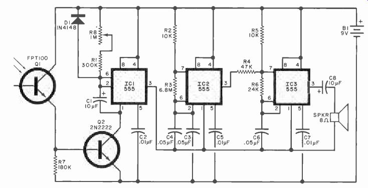
Fig. 1. Timing action of circuit is initiated by light striking Q1.
PARTS LIST
B1--9-volt battery
C1--10-µF, 25-V tantalum capacitor
C2, C5, C7--0.01-µF disc capacitor
C3,C4,C6--0.05-µF disc capacitor
C8--10-µF, 25-V aluminum capacitor
D1--1N4148 or similar diode
IC1, IC2, IC3--555 timer
Q1--FPT 100 or equivalent
Q2--2N2222 or similar transistor
All resistors: 0.25-watt, 10% tolerance:
R1--300,000 ohms
R2, R5--10,000 ohms
R3--6.8 megohms
R4--37,000 ohms
R6--24.000 ohms
R7--180,000 ohms
R8--1-megohm trimmer potentiometer
SPKR-Miniature
8-ohm loudspeaker
Misc.--Battery holder; translucent plastic refrigerator container (about 3" square); silicone-rubber cement; hookup wire; etc.
Note: The following items are available from Rand Laboratories, P.O. Box 468, Cape Canaveral , FL 32920: complete kit of parts including drilled case for $9.95 postpaid.
Also available; pc board only, $4.25 postpaid. Florida residents. please add sales tax.
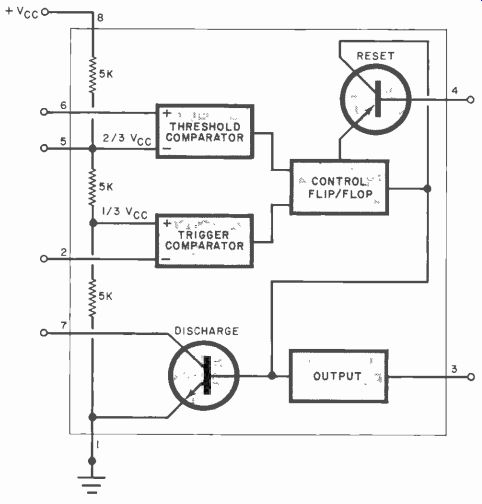
Fig. 2. Block diagram of principal circuits in the 555 IC. In this case,
one 555 is used as timer, and two us astable multi vibrators.
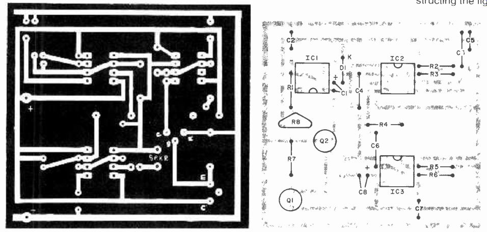
Fig. 3.
Source: (Popular Electronics Electronic Experimenter's Handbook (1982)
Also see: