An inexpensive solid-state controller that reduces inefficiencies in electric motors such as those used in refrigerators and dishwashers has been developed at the NASA Marshall Space Flight Center (by Frank J. Nola). Since total electric energy consumed by motors in the U.S. is equivalent to six-million barrels of oil per day and 25% or more of this electricity is pure waste in the form of heat and other factors, the discovery's import is obvious.
The NASA-developed controller is meant to work with ac induction motors, probably the type most widely used today. They characteristically run at a nearly constant speed that's fixed by power-line frequency and independent of load and supply voltage. When heavily loaded, the motor draws line current that is nearly in phase with the applied voltage, keeping its power factor (cosine of the angle between current and voltage) high and developing a large torque.
Under light load conditions, the motor develops less torque by allowing more lag between the voltage and current. This reduces the power factor while leaving the current essentially the same in magnitude.
Though the low power factor means that conversion of electricity to mechanical power is small, the large current causes considerable I^2R losses (heat) in the supply lines and motor windings.
This is what reduces efficiency. To minimize this waste, Nola's device monitors the motor's power factor and, when it detects light load conditions, it reduces the supply voltage. This increases "slip" in the motor, which causes a speed reduction of 2% or less so that the motor acts as if it were heavily loaded.
The current, now more nearly in phase with the voltage, therefore does as much useful work as before, but it and the voltage are smaller, resulting in a net saving of electric power.
Power Savings. The device was tested at Marshall Center on over 40 types of motors. Power savings ranged to 60%, depending on the loading. Up to 40-50% power reductions are claimed for motors running lightly or intermittently loaded.
The savings derived by using the controller with motors driving relatively constant loads (refrigeration systems and pumps, for example) are smaller, since the device can then do little more than reduce the 8-10% safety factor allowed for low-voltage conditions. On the other hand, since such motors typically have long duty cycles, significant economies may be realized over a period of time.
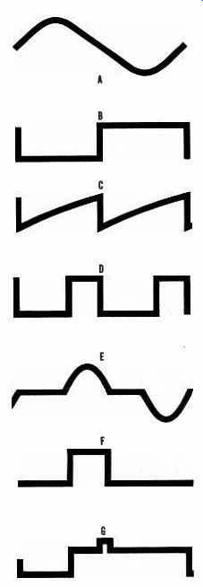
Figure 1 was constructed from data averaged from tests made on a 1/2-hp split-phase motor, and 1/3- and 1/4-hp capacitor-start motors. The top curve shows the typical power required for various loads when no control system is used. The lower curve shows the power consumed when the power-factor controller is used. The controller reduced the no-load power drain by a factor of 5 or 6 and increased the power factor from 0.2 to 0.8. In all three motors, the speed reduction resulting from lower voltage was less than 2%. Circuit Operation. The circuit shown in Fig. 2, which is a simplified version of the original invention, operates in exactly the same manner. Also shown in Fig. 2, facing the diagram are waveforms for the corresponding letter-in-a-circle points on the schematic.
Typically, current may lag the voltage by 80° in an unloaded motor and only 30° when loaded. The controller continuously monitors phase angle between voltage and current, producing a voltage proportional to that phase angle. This voltage is summed with a preset reference voltage that corresponds to a desired phase angle. The difference between the two produces an error signal that biases a ramp voltage synchronized to the 60-Hz line voltage.
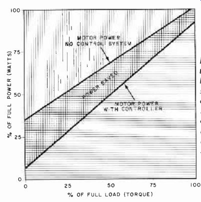
Fig. 1. These curves are the results of tests made by NASA on a 1/2-hp
split-phase and 1/4- and 3/4-hp capacitor-start motors.
Note that the power-factor controller reduced the no-load power demand by a factor of 6. Motor slowdown was less than 2%.
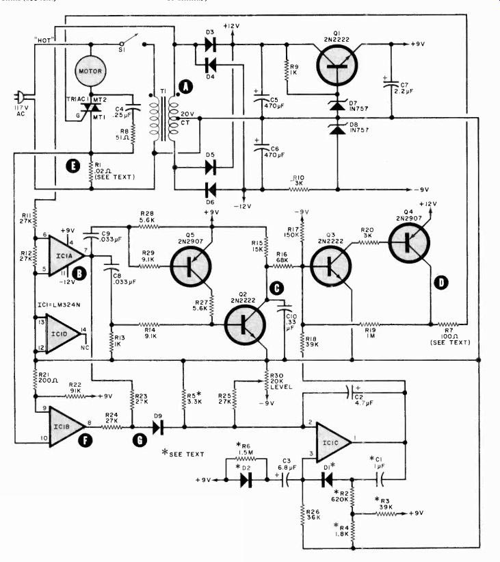
Fig. 2. In essence, the controller corrects the phase angle between motor
voltage and current to reduce power required when motor is operating at
less than full load.
Letters in circles on schematic refer to waveforms at left.
===========
PARTS LIST
C1--1-µF non-polarized capacitor, Mouser Electronics 19NK001 or equivalent
C2--4.7-µF, 20-V electrolytic
C3--6.8-µF; 20-V electrolytic
C4--0.25-µF, 400-V capacitor
C5,C6--470-µF, 35-V electrolytic
C7--2.2-µF, 20-V electrolytic
C8, C9--0.033-µF capacitor
C10--0.33-µF capacitor
D1 ,D2,D9--1N414S or 1N914
D3 through D6--1N4001 or similar
D7, D8--1N757, 9.1-V, 400-mW zener
IC1-Quad 741 opamp, LM324N
Q1, Q2, Q3--2N2222 or similar
Q4,Q5--2N2907 or similar
Following are 1/4-watt, 5% resistors unless otherwise specified:
R1--0.02 ohm, 5 W (see text)
R2--620,000 ohms (see text)
R3, R18--39,000 ohms (see text for R3)
R4--1800 ohms (see text)
R5--3300 ohms (see text)
R6--1.5 megohms (see text)
R7-100 ohms, 2 W (see text)
R8-51 ohms, 1 W
R9, R13--1000 ohms
R10,R20--3000 ohms
R11, R12, R23, R24, R25--27,000 ohms
R14,R29--9100 ohms
R15--15,000 ohms
R 16-68,000 ohms
R17-150,000 ohms
R19--1 megohm
R21--200 ohms
R22--91,000 ohms
R26--36,000 ohms
R27,R28--5600 ohms
R30--20,000-ohm linear taper pot. (see text)
S1-Spst switch
T1-- 20-V CT, 0.3-A secondary (115/220 volt version is Signal DP-241-4-20 or similar)
Triac-200-V, 15-A (400-V unit for 220-V operation is available. See note below.)
Misc.-Suitable enclosure, heavy-duty ac line cord (male and female connectors), mounting hardware, etc.
Note: The following items are available from M.H. Marks Enterprises, 315 Thornberry Ct., Pittsburgh, PA 15237: Complete kit of all parts for 115-volt system (includes triac, printed circuit board, line cord, cabinet, hardware) for $35.95; complete kit as above for 220-volt system for $41.95; kit of all parts not including line cord, cabinet, hardware for $29.95; etched and drilled printed circuit board for $10.95. Please add $3.00 per kit for shipping and handling on domestic orders, appropriate postage for 3 lb for foreign orders.
Pennsylvania residents, please add 6% sales tax.
============
The intersection of the ramp and the error voltages is detected by a squaring amplifier whose output provides proper timing for controlling a triac in series with the motor. The triac is triggered at a point during the cycle, and the circuit switches to "off" as the line current goes through zero. Triggering the triac earlier in each half cycle raises the average voltage to the motor and vice versa.
The triac's control signal is created by sensing the voltage (A) developed at the top end of transformer T1--which also serves as the power source for the conventional dc supply. (Note how the secondary of T1 is phased with the primary ac power.) The voltage is applied via R11 to the input of op-amp IC1A. Since this op amp is operating at full gain, the output is a square wave at power -line frequency. This IC has two outputs (B). One, via C8 and C9, drives the ramp generator, which consists of Q5, Q2, and associated components. Capacitor C10 charges through R15 to form the ramp. The positive-going step from IC1A turns on Q2, thus rapidly discharging C10 to complete the ramp function. The negative-going step from IC1A turns on Q5, which, in turn, causes Q2 to saturate, thus discharging C10.
Since IC1A is triggered at power-line rate, the ramp generated across CIO is synced to the power line, with each ramp occupying a half power-line cycle.
The other output of IC1A is coupled through R23 to diode gate D9.
A voltage proportional to the current through the motor (E) develops across sensing resistor R1. This voltage is passed to IC1B, whose squared -off output (F) is passed through R24 to diode D9, where it combines with the output of 1C1A to make waveform (G). The summed voltage at the cathode of D9 is differentiated and fed to integrator IC1A, along with a dc control level determined by LEVEL potentiometer R30. This control is used to set the motor's optimum phase angle. Time constant network C3 and R26 provide a delay to let the motor develop maximum torque when first turned on. Capacitor C2 provides the high-frequency roll-off necessary for system stability.
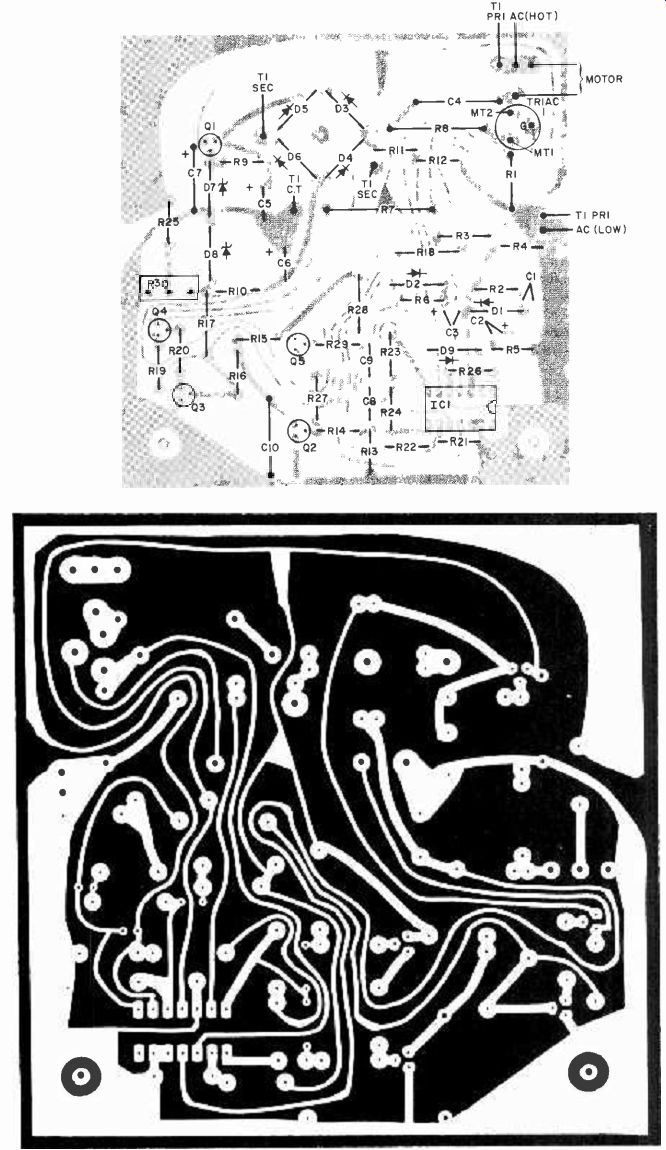
Fig. 3. Actual-size etching and drilling guide for a printed-circuit
board for the controller is shown above.
Component layout is at top.
Note that there are several different options regarding components and construction, as outlined in text and Parts List.
Since suddenly applied loads may cause the motor to stall if the system reacts too slowly, the circuit contains some components to prevent this from happening. These parts, which alter the integrator's time constant, are shown with an asterisk in Fig. 2 (R2, R3, R4, R5, R6, D1, D2, and C1). If you do not need this capability, eliminate these components and tie the positive end of parallel with the ramp from C10.
Triac controller Q3-Q4 is normally biased off by R17. When the composite signal (ramp plus pulse) arrives at the base of 03, this transistor will turn on when the peak of the composite signal overcomes the bias. Since the ramp level is fixed, the pulse from IC/C, controlled by R30, determines when the Q3-Q4 combination turns on. When turn-on occurs, the waveform shown at (D) triggers the triac, thus applying voltage to the motor.
Construction. The circuit can be most easily assembled on a pc board using the foil pattern and component layout shown in Fig. 3. A bridge rectifier can be used in place of the four rectifier diodes (D3-06). If a 24-volt transformer is employed, increase the value of R7 to 150 ohms. Resistor R1 can be fabricated from a 9" length of #22,ora10"length of #24 solid copper wire that's wound on an insulated support dowel.
At this time, you make the decision about the aforementioned possibility of sudden or clutched-in loads that would require using the asterisked components. Furthermore, if this device is to be used with motors requiring in excess of 300 watts, to prevent damage to the triac or pc board, remove the triac, R1 and the ac input from the board, mounting a terminal strip in their place. Mount the triac with R1 to the chassis or optional heat sink (suitably isolated) and wire them into the circuit board, using the terminal strip. Make sure that the "low" side of the ac line is used as the circuit common, and use polarized plugs for all ac-power connections. Do not use the metal chassis as the common ground! Failure to observe these precautions may cause a serious shock hazard.
Mount the pc board and transformer in a chassis, securing the board on insulated spacers so that no part of the ac line makes contact with the chassis. If desired, LEVEL potentiometer R30 can be removed from the pc board and a conventional rotary potentiometer of the same value can be mounted on the chassis. The motor can be plugged into an optional socket mounted on the chassis (wired to the motor-connector pads on the pc board), or use a suitable length of heavy-duty ac line cord having a socket at one end. Do not forget to use ac line cord having sufficient current--carrying capacity to handle the load.
Since many of the systems to which the controller can be usefully applied have motors fed from 220-volt ac mains, you may wish to adapt the circuit to work at that voltage. This can be done by exchanging T1 for a similar transformer with twice as many primary turns and substituting a higher voltage triac (400 PIV minimum). Both "hot" legs of the 220-volt line should be isolated from the chassis, while the center tap should be connected to the ground circuit. An appropriate line plug and receptacle can be used, or the controller can be hardwired to the load.
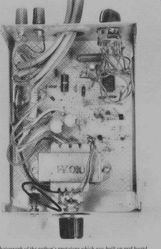
------------- Photograph of the author's prototype which was built
on perf board, though a printed circuit board is recommended. The binding
posts and switch on the rear were used for testing during design.
Use. Plug the power-factor controller into an ac outlet and connect the motor to be controlled. Turn both on. With the motor operating, slowly adjust LEVEL control R30 until a slight drop in speed or mechanical power is noticed. Vibration, too, will probably diminish. Slightly back off on R30 until you feel the point where the speed barely drops off. This should be the optimum setting of the controller. It will probably be necessary to readjust R30 for each different motor you wish to control.
As noted earlier, the savings effected by using the power factor controller (and the length of time required for the device to pay for itself) depend on the way in which a particular motor is loaded and for what proportion of the time it is in use. Clearly, intermittently used appliances such as power tools are poor candidates. In most households, refrigerators, air conditioners, ventilating fans, swimming-pool pumps, and other machines that run for extended periods will let the power factor controller pay for itself more quickly than smaller and/or intermittently used appliances. Savings will depend on your electric rates, too. In New York City, where one kilowatt-hour costs 11.5 cents in the summer and 9.52 cents in the winter, the controller, used on a 16-cu-ft frost-free freezer, might well pay for itself in about two years.
Source: (Popular Electronics Electronic Experimenter's Handbook (1982)