BY DON MORAR
Inexpensive bridge measures R and X components over a wide frequency range.
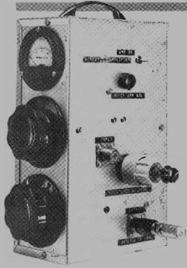
ONE OF the most useful instruments an experimenter who works with r-f circuits can have is an impedance bridge. The ideal bridge would permit accurate measurement of both the resistive and reactive components of an unknown impedance over a wide range of frequencies. Commercial r-f impedance bridges, although they satisfy these requirements, are priced well beyond the means of the average experimenter. On the other hand, those affordable bridges that have appeared as construction projects in amateur radio and hobby electronics magazines only tell half the story--the resistive component.
The bridge described in this article can measure the complex impedance of just about any load at frequencies between 3.5 and 54 MHz with a high degree of accuracy. Moreover, it can be inexpensively built using "junk box" components, and is smaller and lighter than its typical commercial counterpart.
The only external items required for calibration and operation are a group of nonreactive resistors, an r-f source such as a signal generator, and, of course, the impedance to be measured.
Among the project's features are a built-in null indicator (a microammeter) and an amplifier which can be switched into the null detector circuit to enhance its sensitivity. The value of the impedance's resistive component is read directly off the bridge's R dial, which is calibrated in ohms. The unit's x (reactance) dial calibration is scaled in terms of frequency. This is done because inductive and capacitive reactance vary with frequency, so an x dial calibrated directly in ohms would be accurate at only one specific frequency. Scaling the x dial's calibration in terms of frequency provides greater operating flexibility.
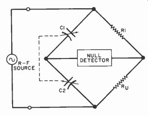
Fig. 1. Basic r-f bridge uses dual differential capacitor but gives
only resistive information.
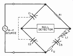
Fig. 2. More sophisticated bridge can measure reactance as well as resistances.
About the Circuit. The schematic diagram of a basic r-f bridge is shown in Fig. 1. It obviously resembles the classic Wheatstone bridge, which has four resistive arms. Two of these arms are usually derived from a potentiometer. The r-f bridge, however, employs a dual differential variable capacitor (C1C2) so that measurements can be performed over a wide range of frequencies. If a potentiometer were used, its frequency-dependent intrinsic reactance would cause the bridge to yield false results.
Some readers might not be familiar with the dual differential capacitor. It is, essentially, two variable capacitors ganged so that when one section (capacitor) exhibits maximum capacitance, the other exhibits minimum capacitance. The use of a dual differential capacitor provides a variable capacitance ratio between the two arms of the bridge that it comprises. This simplifies the calibration and use of the bridge. If the value of R1 is a constant, the single control knob used to vary the setting of C1C2 can be calibrated in terms of R1 or in ohms.
To use the bridge the unknown impedance is connected as Ru and an r-f source is used to energize the network. The dual differential capacitor is then adjusted so that the bridge is balanced. When that happens, no voltage drop will exist across the bridge detector and no current will flow through it. The detector will indicate a null and the value of Ru can be read off the dual differential capacitor's control knob.
The bridge in Fig. 1 will only measure the unknown's resistive component. More complete information about the unknown (including its reactance) can be obtained by measuring it on the bridge shown in Fig. 2. This circuit resembles that of Fig. 1, but two components (C3 and L1) have been added to the bridge's lower right arms. To underscore the bridge's greater measuring facilities, the unknown is no longer represented as a resistance (Ru), but as a general impedance (Zu). As in Fig. 1, dual differential capacitor C1C2 is used to measure the real (resistive) component of the unknown complex impedance. Variable inductor L1 and variable capacitor C3 make possible measurement of both the sign and magnitude of the unknown's imaginary (reactive) component. The bridge thereby provides the user with complete information about the unknown impedance.
The device is initially balanced at the frequency of interest with a purely resistive termination at Zu. Variable capacitor C3 is placed at its midrange setting and inductor L1 is adjusted for resonance. This cancels out any reactance which would otherwise be reflected into the other bridge arms. The nonreactive termination is then replaced with the unknown impedance. Its resistive component is balanced by varying C1C2 and its magnitude read off the calibrated capacitor control knob scale. The unknown's imaginary component is balanced by shifting C3 away from its mid--scale setting in either the clockwise (4 , the standard sign for inductive reactance) or counterclockwise (-, the standard sign for capacitive reactance) direction to cancel out any reactance in the unknown.
==============
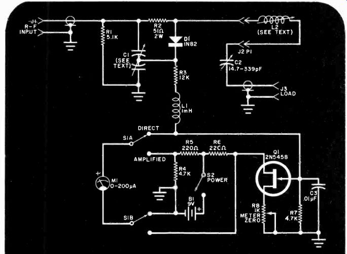
Fig. 3. Complete schematic dia.g ro aai of the r-f impedance bridge.
Amplifier Q1 enhances sensitivity a aad increases null resolution.
PARTS LIST
B1-9-volt transistor battery " 6" x ; I'2" (25 _-1 x 15.2 x 8.9 CI-Dual differential variable capacitor, 12-to -150 pi' per section. Millen No. 28801 or equivalent (see text)
C2--4.7-to-339-pF variable capacitor (Mil--ten No. 19335 or equivalent)
C3---0.01-µF disc ceramic capacitor
D1 -1N82 or equivalent germanium diode 11,33-SO-239 coax 1,11 connector
J2-Standard Amphenol 4 prong jack
LI -1 -millihenry inductor
L2-See text and Table Mt -0 -to -200-µA meter P1---1-prong plug to malt! 42 QI-2N54SX n-chanunel JI E")
The following, unless otherwise itied. are (4 -watt, 5% tolerance, fixed carh<,n-conrprr sit on resistors.
R1-5100 ohms R2-51 ohms, 2 watts R3-12,000 ohms R4,R7-4700 ohms R5,R6-220 ohms R8 -1000 -ohm potentiometer S1-Dpdt toggle switch cm) aluminum utility hox ( Bud Ct.'3010A or cyno-dicm). 5i,ß' .. 2s "113.4 X (r x 5.4 cm) aluminum utility box (Bud (1 3006A or cquivdient). LW. Miller No. 42000031 or equisaler t slug -tuned coil f,nirs, plague or metal threaded BX/Romex ,lurdr'or electrical -box plugs_ 1-r-inch (3.8--nu PVC pipe, PVC pipe adapter, l'::. -inch or I.3 -em threads to t -2 -inch or I r pipe), eyanoacrylate cement, control km'h, with !ir -inch (3.3 -mm) shalt hole, one control knob with 1 -inch (6.6 -mm) hall hole, two large Bakelite control knobs with Inch 16 n -nun) shaft hole threaded pore ;tandotl s. one non insulated and two ur,ulati d 1/4 -inch in .6-rums shaft couplings. I br.rrlets, hatter r lip. Kittery holder. perforated hoard. several non-reactiie resi,too whose values have been accurately determined. PL -259 coaxial connectors, convenient lengths of 50 -ohm coaxial cable, enamelled copper , wire, hookup wire, solder lugs, solder, machine and self -tapping hardware, etc.
===============
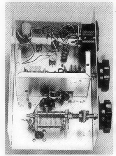
Fig. 4. Photo of author's prototype. Note small shielding box (half of
which has been removed) partially obscuring dual differential variable capacitor.
If the unknown impedance has an inductive component, more capacitive reactance (that is, less capacitance) is required from C3 to obtain a balance.
Conversely, if the load has a capacitive component, more capacitance and less capacitive reactance is required. Once C3 has been properly adjusted, the bottom right leg of the bridge will look purely resistive, and an excellent null will be obtained on the detector.
The scale of C3's control knob should be calibrated in terms of the magnitude and sign of the reactance present at Zu.
Because inductive reactance varies directly with frequency and capacitive reactance varies inversely with frequency, the calibration of C3's control knob must be scaled in terms of frequency. If it were calibrated directly in ohms, its calibration would hold true at one frequency only. A better approach is to perform the calibration at 1 MHz and frequency--scale it. The exact magnitude of the reactive component can then be determined by a simple arithmetic operation.
The complete schematic of the r-f impedance bridge is shown in Fig. 3.
Resistive balancing is performed by dual differential capacitor C1. Noninductive resistor R2 provides the reference against which the resistive component of the unknown impedance is measured.
(The unknown is connected to LOAD jack J3.) Balancing and measurement of the unknown's reactive component (if any) s the task of L2 and C2.
When the bridge is unbalanced, germanium diode D1 rectifies r-f into pulsating dc which is filtered by L1 and C3. If S1 is placed in its DIRECT position, the filtered dc is applied to null indicator M1, a 0-to-200-µA meter. For increased resolution of the null, S1 should be placed in its AMPLIFIED position. The filtered dc is then amplified by Q1, which in turn drives the meter movement. Use of the amplifier also increases bridge sensitivity so that the circuit is compatible with low-level signal sources such as solid-state "grid" dippers.
Construction. In any r-f bridge, it is essential that residual and stray reactances be kept to a minimum, and this project is no exception to that rule.
Placement of components must be such that lead lengths in the r-f portion of the circuit are absolutely as small as possible. The layout established by the author, which can be seen in the photograph of his prototype (Fig. 4), yielded good results up to 54 MHz.
All of the components were mounted in an aluminum utility box measuring 10" x 6" x 3 1/2f (25.4 x 15.2 x 8.9 cm). The frames and stators of variable capacitors C1 and C2 must be insulated from ground (the enclosure), necessitating the use of threaded porcelain spacers or their equivalent. Similarly, insulated couplings should be used with the capacitors' control shafts.
Dual differential capacitor C1 is partially hidden in the photograph by one half of an aluminum utility box which mounts inside the main enclosure and shields the capacitor from the rest of the bridge. (The other half of the utility box has been removed to expose the capacitor for the photograph.) Dimensions of the box shield used by the author are 5 1/4" x 3" x 2 1/4" (13.4 x 7.6 x 5.4 cm). Totally enclosing the differential capacitor within the grounded utility box helps keep stray reactances small.
To cover 3.5 through 54 MHz with one variable capacitor (C2) requires the use of several different inductors. However, band switching of the inductors is not used in this project because it would introduce too much stray reactance and degrade bridge performance. The author's solution to this problem is to use plug-in inductors. J.W. Miller coil forms (No. 42000CBI), 1/2-inch (1.3-cm) inner-diameter PVC pipe fittings, and 4-prong plugs are used in making the coils.
Details of coil construction are shown in Fig. 5. First, the various coils should be wound on slug-tuned forms. Coil winding data appears in the Table. After the coils are wound, they should be soldered to standard Amphenol four-prong plugs. (Bases removed from discarded four-prong vacuum tubes can be used instead of four-pin plugs.) Take the suggested PVC pipe fittings and modify them as shown in Fig. 5. Then affix each four-pin plug to a modified PVC fitting with cyanoacrylate cement (Eastman 910, "Krazy Glue," or equivalent).
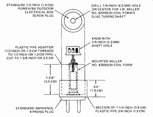
Fig. 5. Assembly details for each plug-in coil (L2).
Using a 1/4-inch (6.5-mm) bit, drill out the center of a 1/4-inch (1.3-cm) plastic or metal threaded BX/Romex outdoor electrical-box plug to accommodate the Miller coil form's metal bushing. Mount the threaded plug in the PVC fitting and attach a knob to the coil form's tuning shaft to complete the coil assembly. Repeat this procedure for each inductor.
Either a commercial dual differential capacitor or a home-brew one can be used for C1. The dual differential capacitor should have a capacitance of 12-to-150 pF per section. A Millen No. 28801 dual differential capacitor is suitable, but the author ganged two identical Hammarlund receiving-type variable capacitors rated at 12-to-150 pF each. If two capacitors are used, they should be ganged so that one is at maximum capacitance (plates fully meshed) when the other is at minimum capacitance (plates fully open). The other variable capacitor, C2, is rated at 14.7-to-339 pF. A Millen No. 19335 or equivalent component Is acceptable.
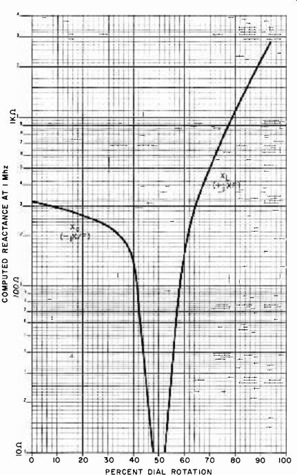
Fig. 6. Calibration curve for the X (reactance scale of C2's control
knob.
The frames of both C1 and C2 should be mounted on insulated standoffs, and insulated shaft coupling should be used to connect their rotor shafts to the short shafts to which the R and x control knobs are attached. Note that if two capacitors are ganged to form a dual differential unit, a noninsulated coupling should be installed between the two rotor shafts.
Other details of the construction of the author's prototype are apparent in Fig. 4. A portion of the small shield box has been cut away with a nibbling tool to provide room for J1, R1, R2 and the lead connected to the rotor plates of C1. The null detector's amplifier is mounted on a small piece of perforated board which is mechanically supported by L brackets secured to the terminals of M1. Because parts placement is critical in the r-f portion of the project, it is best to duplicate the author's layout closely.
Calibration. The resistance (R) dial of the impedance bridge can be calibrated by using an assortment of 1/2-watt carbon composition resistors of various values within the 5-to-200-ohm range. The author measured the exact resistance of each component selected on a General Radio GR-650 bridge to enhance the accuracy of the calibration. If you don't have access to a highly accurate bridge, measure the resistors with a good-quality digital multimeter or use close-tolerance metal film components. Connect the resistors to PL-259 coaxial plugs, keeping lead lengths short.
Calibration should be performed at 3.5 MHz to minimize the effects of reactive strays. Apply the output of a signal generator oscillating at that frequency to J1 and connect the first load resistor (the one with the lowest resistance) to J3.
Also, install the 80-meter plug-in coil at J2. With S/ in its DIRECT position and C2 set at 50% dial rotation (plates half meshed), adjust C1 and L1 for the best null possible. Then place S1 in its AMPLIFIED position and fine-tune for the deepest null you can obtain. Place a notch, tick mark, or other notation of the position on C1's dial. Repeat this procedure for each calibrating resistor.
The author used Bakelite knobs with large skirts as the x and R control knobs.
Calibration of the R knob was made by inscribing the appropriate point on the Bakelite skirt with tick marks and numerical values using an electric engraving tool. This technique permits direct calibration of the R knob in ohms. (Suitable Bakelite knobs are available from such surplus electronics dealers as Fair Radio Sales Co., Box 1105, Lima, OH 45802.) Alternatively, a knob with a silver skirt calibrated from 0 to 100 over 180 degrees of dial rotation can be used in conjunction with a graph of dial readings plotted against resistance values.
No direct calibration was performed on the x (reactance) dial. Rather, the following procedure was followed. Using a Southwest Technical Products digital capacitance meter cross-checked against a General Radio GR-650 bridge, the author made a plot of the capacitance of C2 against dial rotation. Then the standard inductive and capacitive reactance formulas were employed to derive a plot of reactance below and above a resonant frequency of 1 MHz.
Assuming that L2 is adjusted to cancel out bridge reactance (including that of C2 when its plates are half meshed), the graph shown in Fig. 6 plots the net reactive variation of XC and XL below and above the resonance at 1 MHz.
This graph can be used to calibrate the x control knob. For example, at 50% dial rotation, the reactance of the load is 0. At 75% dial rotation, the reactance is +j740 or 740 ohms inductive. Similarly, at 25% dial rotation, the reactance is -j250 ohms or 250 ohms capacitive. As was done with the R control knob, a Bakelite knob with a large skirt can be used and the skirt inscribed with an electric engraving tool. Alternatively, a knob with a silver skirt calibrated from 0 to 100 over 180 degrees of dial rotation can be used in conjunction with the graph of Fig. 6 to determine the sign and magnitude of the reactive component.
The accuracy of the x control knob's calibration depends on that of the graph of Fig. 6 and the degree of bridge balance (null sharpness) obtainable. The theoretical curve is apparently very accurate. How much a direct calibration would depart from the curve would depend on stray bridge reactance. The prototype yielded good, sharp nulls and its x calibration was very accurate.
Using the Bridge. Before an unknown impedance can be measured, it is necessary to balance the bridge. Apply an r-f signal to JI and connect a non-reactive termination to J3. (The author employs a commercial 50-ohm, 5-watt nonreactive termination when performing this step.) Any signal source producing 1 to 3 volts rms of r-f can be used. A grid -dip oscillator loosely link -coupled to J1 is satisfactory. The author employs a 4-turn coil of No. 16 enameled copper wire large enough to accommodate the outer diameter of his grid-dip coil to apply r-f for 80- and 40-meter measurements and 2 turns of the same wire for measurements on 20, 15, 10, and 6 meters. Each coil is connected to a convenient length of 50-ohm coaxial cable, the other end of which is terminated with a PL-259 connector.
Plug the appropriate coil for the frequency at which the measurement is to be performed into jack J2. Then set the x control knob to 0 ohms (50% rotation or midscale). Adjust C1 and L2 for a good null as indicated by M1. After initial adjustments, switch the amplifier into the meter circuit to increase the resolution of the null. If a complete null cannot be obtained, reduce the coupling between the signal source and the bridge.
After the bridge has been balanced, replace the purely resistive load with the unknown impedance. Alternately adjust C1 and C2 to obtain the best null and note the readings of the R and x scales.
Impedance measurements are in rectangular form. An impedance with an inductive component is of the form Z = R + jXF, where R and X are the readings of the R and x scales, respectively. The operator +j denotes inductive reactance, and F is the frequency at which the measurement is performed. An impedance with a capacitive component is of the form Z = R-jX/F, where R, X, and F are as defined in the case of a partially inductive impedance. The operator -j denotes capacitive reactance.
As mentioned earlier, the x measurement involves frequency scaling. In the case of an inductive reactance, the exact magnitude is determined by multiplying the x scale reading by the frequency at which the measurement is performed.
The exact magnitude of a capacitive reactance can be obtained by dividing the x scale reading by the frequency at which the measurement is made.
In Conclusion. Here are a few hints that you should keep in mind when using this project. Bridge measurements are of course frequency sensitive. The bridge must therefore be rebalanced after a frequency change of 1% or more occurs. Be sure to balance the bridge with a purely resistive test load before performing any measurements. Otherwise, inherent bridge reactances will cause a false reading.
Remember that the bridge requires very little r-f drive. This is no problem when a signal generator or grid -dip oscillator is used as the signal source because the output level of the generator or the coupling between the oscillator and the bridge can be easily reduced.
However, if a transmitter is used to provide r-f for the impedance measurement of, say, an antenna or linear amplifier input stage, care must be taken not to overload the bridge. The transmitter's r-f output must be kept at a low level, and the bridge must not be left in the line when more than 0.1 watt of r-f power is flowing.
It is usually very inconvenient to perform impedance measurements directly at an antenna's feed point, so they are commonly performed at the transmitter end of the transmission line. This can result in misleading information if the line is not an integral multiple of an electrical half-wavelength. Note that a transmission line's electrical length is its physical length expressed in free -space wavelengths at the frequency of interest multiplied by the line's velocity factor. Solid-dielectric coax (RG-58, RG-59, RG-8, RG-11, etc.) has a velocity factor of approximately 0.66; polyfoam coax has a velocity factor of approximately 0.81.
If it is not convenient to add or subtract enough cable to make the transmission line an integral multiple of an electrical half -wavelength, a Smith chart can be used to transpose the measured impedance at the transmitter end of the line into the actual antenna impedance.
To do this, the line length must be accurately determined by physical measurement or by measuring it with a grid-dip oscillator and the far end of the line shorted. Remember that you must employ the electrical length of the line when using the Smith chart.
You are now ready to start using your impedance bridge in r-f work. Its usefulness on your test bench or in your radio shack will be quickly appreciated.
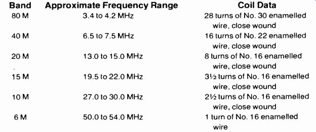
COIL WINDING DATA ---All coils are to be wound on a J.W. Miller No.
42000CBI or equivalent slug -tuned form.
Source: (Popular Electronics Electronic Experimenter's Handbook (1982)
Also see: