BY TOM KRONENWETTER
Checks all signals on an IC simultaneously
USING single-LED logic probes is the most common way to check the logic operation of a digital IC. This is fine as long as all you want to know is whether a particular pin is high or low or is switching between these two states. But most logic circuits require that correct timing be maintained between a number of signals from the same IC. This is something that a single-LED probe cannot test.
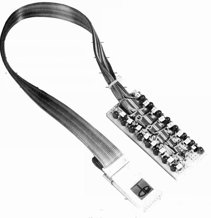
The logic monitor described in this article allows all of the pins of an IC to be examined simultaneously, which means that timing can be observed. The monitor reads out via 16 LEDs, each connected via a high-input resistance driver to a pin of the IC. Interconnection between the monitor and the IC is through a length of ribbon cable terminated to a clip that clamps on to the IC.
The project can be constructed for 8-, 14- or 16-pin DIP packages. If desired, it can be expanded to handle 40-pin devices. The monitor is powered from the circuit under test. Operating characteristics are given in Table 1.
Basic Circuit. As shown in Fig. 1, the basic circuit consists of a relatively high-input resistance (100,000 ohms) Darlington transistor driving a LED. Resistor R2 ensures that when the input is logic 0 (low), the transistor will be cut off and the LED will remain dark. This circuit is duplicated for each required pin connection. Current-limiting resistor R3 is common to all LEDs.
Construction. In constructing the logic monitor, a solderless breadboard (see photo) is used. In this breadboard, the five holes across each row are interconnected inside the plastic housing.
Start assembly in one corner of board. Skip two holes and install a LED in third and fourth holes with the LED cathode in hole 4 as shown in Fig. 2. Install the transistor in the second column with the collector lead in the same row as the LED cathode, the base lead in the fifth row hole and the emitter lead in the sixth row hole. The cathode of the LED is thus connected to the transistor collector internally.
Cut one lead of a pair of 100,000-ohm resistors to 0.7" and the other lead to 0.3". Each of these resistors will be mounted vertically. Insert the short lead of R2 into the second hole past the LED, then bend the longer lead over and insert it into the hole adjacent to the LED. Thus R2 is connected between the base and emitter of Q1. Insert the long lead of the remaining resistor into the hole above the base of Q1 so that it connects to the base of Q1. The short upper lead of this resistor will be connected to the cable later on.
If you are making a 16-pin arrangement, follow the above assembly procedure seven more times to produce eight LEDs on one side. If you are making a 14-pin array, then only seven LEDs are needed.
To complete the assembly, start the component installation at the diagonally opposite corner (no hole spaces), and work up the other side. Resistor R3 is installed in a hole near the last LED.
Cut 32 one-inch long jumpers from #22-gauge solid insulated wire and strip 0.3" of insulation from each end. Six teen of these jumpers are used to inter connect the 16 ground points to form a common bus. The remaining jumpers are used to couple the anodes of all the LEDs into a common bus. This bus is then connected is to R3.
At this time, each LED must be identified as to pin number. Make up some small stick-on labels, each identified in numerical sequence from 1 to 16, and affix one to the top of each transistor.
The sequence should be 1 through 8 from top to bottom on the left side, and 9 through 16 from bottom to top on the right side.

TABLE I OPERATING CHARACTERISTICS

TABLE II CABLE COLOR CODE
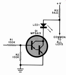
Fig. 1. Basic circuit consists of a Darlington transistor driving a LED.
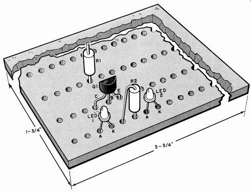
Fig. 2. Start the assembly as shown here in the upper left corner of
board.
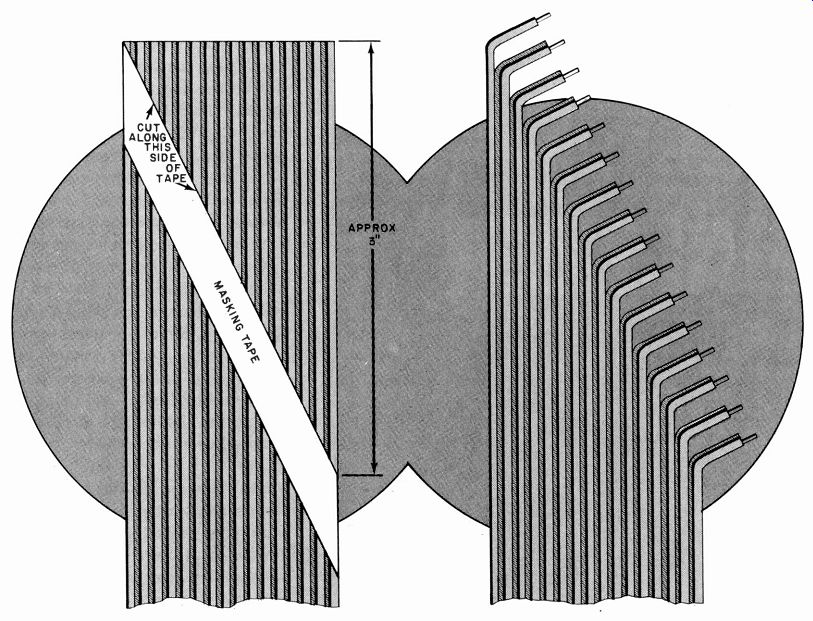
Fig. 3. The 16-lead ribbon cable is prepared as shown here with the leads
cut diagonally so that they can be connected easily to circuits on the
board.
----------
PARTS LIST
LED1-Red LED (FLV-117 or similar, 16 required)
Q1-MPSA13 Darlington transistor (16 required)
R1, R2- 100,000-ohm, 1.4-watt resistor (32 required) R3-56-ohm, 14-watt resistor
Misc.-Solderless breadboard (AP Products Model 234), 16-pin clamp-on logic clip with cable (AP Products Model LC 160), small tie wrap, 422 AWG wire, labels.
--------
The final step is wiring the 1.5-foot ribbon cable from the clamp-on connect or to the breadboard. Lay the connector down with its color-coded side facing up.
Using Fig. 3 as a guide, from the tip of the brown conductor at one edge of the cable, measure a diagonal 3-inches long to the blue conductor on the opposite side of the cable. Use masking tape to mark this diagonal. Cut the ribbon cable with scissors along the upper edge of the masking tape. Separate the leads to a length of about one-inch, then strip about 0.2" of insulation from each lead.
Tin each lead and form into small closed loops so that they will fit over the ends of the leads at the top of each R1.
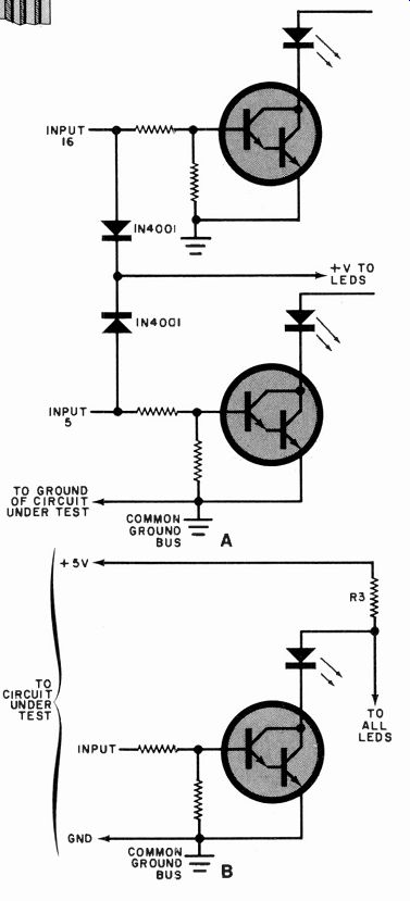
Fig. 4. If pin 5 of the IC to be tested is the dc input and pin 10
is ground, use the circuit at (A). To keep each input isolated from
dc or ground, use the connections at (B).
Place the prepared end of the cable in the center of the breadboard, rainbow side up. Connect the second shortest lead (green) to the short lead of the R1 for the first LED. This corresponds to pin 1 of the connector. The shortest lead (blue) is connected to the R1 associated with the sixteenth LED. Using the cable color-code chart shown in Table II, connect the remainder of the ribbon-cable leads to their respective R1's.
When all the connections are completed, fold the ribbon cable over on itself, slightly above the breadboard, and use a tie wrap to act as a strain relief for the cable.
Most 16-pin DIP packages use pin 16 as the dc source and pin 8 as ground. If you want to follow this convention, jumper input 16 (blue) to the common LED bus, and input 8 (brown) to the common ground bus. This means that the sixteenth LED will always glow and the eighth LED always remain dark.
Some digital IC's, the 7490 as an example, use pin 5 as the dc input and pin 10 as the ground. In this case, the circuit shown in Fig. 4A may be used. Here, two silicon diodes are used to pick off the dc voltage from either the pin-16 or pin-5 inputs for application to the common dc bus. A separate ground lead can be connected between the monitor common-ground bus and the ground of the circuit under test. It is also possible to keep each input isolated from either dc or ground, and use a separate lead connected between the monitor dc bus and the 5 volts of the circuit under test as shown in Fig. 4B. In this latter case, all the LEDs will be active. The human eye can distinguish flashing of the LEDs at rates up to about 15 Hz. Above that frequency the LEDs will appear to be constantly "on." 0