Source: Popular Electronics--Electronic Experimenter's Handbook (1983)

BY DAVID A. ISRAEL
Simple modification circuit upgrades performance of your general-purpose instrument
IF YOU ARE still struggling along with an old, service-type recurrent-sweep oscilloscope, your instrument is woefully inadequate for modern needs. However, one can upgrade such a general-purpose scope's performance at relatively little cost simply by adding the high performance triggered-sweep circuit de scribed here. In comparison with an earlier triggered-sweep add-on (POPULAR ELECTRONICS, May 1978), the new circuit is much faster and triggering sensitivity does not interact with output amplitude among other benefits.
This circuit can be added to most scopes to produce calibrated triggered sweeps at speeds from 0.5 s to 0.5 µs/ division in the standard 1-2-5 format.
In addition to manual trigger-level selection, it features free-run capability with automatic triggering, and adjustable in put-stage gain and frequency response for easy triggering on low-level and noisy signals. A LED tells you when a sweep is being generated. Cost is about $35.
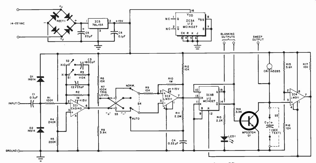
About the Circuit. The heart of the circuit, shown in Fig. 1, is field-effect current regulator CR1. This device adjusts its resistance to provide a constant current with only slight regard (within limits) to the voltage applied across it.
Since the rate of change in voltage across timing capacitor CT is directly proportional to the current flow, keeping the charging current constant causes the capacitor voltage to rise linearly.
Applying this linear ramp waveform to the horizontal axis of the scope makes the electronic beam move equal distances across the CRT screen in equal time increments. The sweep rate is also inversely proportional to the value of CT.
Therefore, to obtain varying sweep rates, the charging current is kept constant, while the value of CT is changed.
The input of IC1 is isolated from dc by C1, while D1 and D2 clamp excessive-amplitude signals. Resistors R4 and R5 provide biasing for IC1 so that the output can symmetrically vary within the supply range. Stage gain for IC1 is either X10 through R2 or X1 through R3. When S2 switches in C3, stage bandwidth is limited to allow reliable triggering on slow input signals on which high-frequency noise is superimposed.
Comparator IC2 determines the actual trigger point on the input waveform.
Two modes of operation are selectable via S4. In NORM, the IC1 signal is compared with a dc voltage set by TRIG LEVEL control R7. When the voltage at the + input of IC2 exceeds that at its- input, IC2's output swings positive, and vice versa. Resistor R10 adds positive feed back to the circuit, and the approximately 0.5-volt hysteresis prevents generation of multiple outputs with noisy input signals.
In AUTO, R7 is switched out of the circuit and is replaced by R11 and C4.
Now, IC2 operates as an astable multivibrator at approximately 50 Hz in the absence of an input signal. This provides a constant scope trace base line for operator convenience and allows dc input levels to be measured.
When a greater than 50-Hz signal is applied to the input, IC2 automatically synchronizes to the input signal. With S4 set to NORM, S3 selects triggering on either the positive or the negative slope of the input waveform. When S4 is set to AUTO, S3 has no effect.
The remainder of the circuit controls the charging and discharging of CT to produce the sweep waveform. When the circuit is quiescent (not triggered), the not-Q output of IC3 is high and Q1 con ducts to discharge CT and prevent recharging as long as not-Q is high.
Note that not-Q also sets the J input of IC3 to high. Since the K input is tied to ground, the flip-flop must change states on the next clock input.
When the positive-going edge of the trigger pulse is applied to the CK input of IC3, the flip-flop changes states. Now, Q1 cuts off and allows CT to charge through CR1 to produce a linear sweep.
When not-Q goes low, Q goes high and TRIGGERED LED1 comes on to signal that triggering has occurred. The J and K inputs of IC3 are now both low, and the flip-flop is immune to any trigger pulses that might occur in the sweep.
The selected CT capacitor charges until the voltage across it just exceeds the voltage at the R15/R16 junction.
When this occurs, comparator IC4, whose output has been at near ground potential, generates a positive reset pulse for IC3. This forces IC3 back into quiescence, turning off LED1 and turning on 01 to rapidly discharge CT. As CT rapidly discharges, the scope's electron beam rapidly retraces to the starting position on the left side of the scope CRT screen.
-----------

Fig. 1. A linear ramp is generated across the timing capacitor by the
current regulator CR1.
PARTS LIST
C1-0.5-µ F, 600-V C2-5-pF ceramic C3-1600-pF ceramic C4-0.22-µF, 50-V miniature monolithic C5-20-µF, 35-V electrolytic C6-0.1-µF, 50-V miniature monolithic Cs-Timing capacitor (see text) C RI- I N 5285 field-effect current-regulating diode, 0.27 mA (Motorola) DI,D2-1N914 ICI-CA3140S MOS bipolar op amp IC2,1C4-L M3 1 I N comparator IC3-MC14027CP dual J-K flip-flop IC5-78 LISA 15-V voltage regulator LED 1-Discrete LED Q I-M PS3704 general-purpose npn small-signal transistor (or similar) RECTI-50- PI V, 1-ampere modular bridge rectifier The following are 1/4-watt, 5% fixed resistors unless otherwise noted:
R1-100,000 ohms R2,R10-1 megohm R3-110,000 ohms R4-240,000 ohms R5-200,000 ohms R6-15,000 ohms R7-100,000-ohm linear-taper potentiometer R8-3900 ohms R9,R12,R16,R17-10,000 ohms R 1 1-2.2 megohms RI3-2200 ohms R14-3300 ohms R15-5600 ohms S1, S2-Miniature spst switch S3, S4-Miniature dpdt switch S5-2-pole, 2-23 position rotary selector switch (Centralab PA-4003 or similar) Misc.-Pc board, mounting hardware, knobs, LED panel-mount adapter.

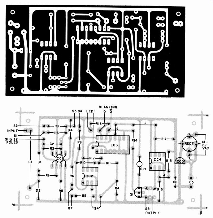
Fig. 2. An actual-size etching and drilling guide for a printed-circuit
board is shown at top. Below it is guide for component placement.
-----------
Construction. With the exception of S1 through S5, R7, and LED 1, which mount on the scope's front panel, all components mount on a small printed-circuit board. An actual-size etching and drilling guide for the board is shown in Fig. 2.
During installation of the components on the board, be sure to observe the proper polarities and orientations of the diodes, CR1, and ICs. Also, be sure to observe the safe handling procedures for IC1 and IC3, which are MOS devices.
The CT timing capacitors mount directly on SWEEP SPEED switch S5. No values are given for these capacitors in the Parts List since they are hand selected to minimize cost while providing the necessary accuracy. More about this under Calibration.
The circuit board is best mounted inside the scope, although a separate case can be used if desired. Inside the scope, try to locate the board as far as possible from heat-producing components. Unless you wish to retain the recurrent-sweep generator in the scope, disable this circuit and remove the associated controls from the front panel.
When mounting the TRIG LEVEL control, switches, and LED 1 on the panel, it may be necessary to drill additional holes to accommodate them.
You may wish to use a rotary switch on TRIG LEVEL control R7 for S4 instead of a miniature toggle switch. This will allow you to turn R7 to one end of its travel to switch the circuit to AUTO. Also, if you wish to avoid drilling holes in your scope, S1 and S2 can be replaced by a double-pole, four-position rotary switch.
If your scope has a + 18- to +30-volt power supply, you can omit RECT1 and connect the dc supply to the input of 105.
Alternatively, you can use a small filament transformer rated at 14 to 22 volts rms to supply power. The circuit draws typically 20 to 25 mA.
The pickoff point for the trigger signal depends on the scope being modified.
Ideally, it should be at a point in the scope's vertical amplifier after the input attenuator and any gain controls so that the input voltage varies over a limited range, in the region of 0.5 to 20 volts peak-peak. (Refer to the schematic diagram of your scope.) In some cases, the scope manufacturer will make this easy for you by using such a point as a source of sync signal to the recurrent sweep.
Your scope may have a horizontal mode selector that provides sync from + and- slopes of input signals, as well as from the 60-Hz line and external sources. This type of selector is an ideal trigger pickoff point and provides switch-selectable trigger signals. If such a switch is present, S3 in the project is redundant and can be eliminated. It is very useful to have the capability to connect the input of the trigger circuit directly to the external input jack because in some cases the poor response of the scope's vertical amplifier will severely limit trigger generator performance at high frequencies.
Connect the sweep output to the input of the scope's horizontal amplifier.
Direct coupling works best. With capacitive coupling, you will have to keep re-centering the trace as the average dc level of the sweep waveform varies with changing proportions of sweep period and repetition rate for different signals.
In some cases, the coupling capacitor at the input of the scope's horizontal amplifier can be removed if it is not blocking a dc bias level that will be fed into the sweep circuit. The sweep output of the trigger circuit is designed to be connected to a typical horizontal amplifier that has a 1-megohm or greater input impedance. Lower impedances will shunt charging current from CT and generate a nonlinear sweep waveform.
If the circuit you are driving has less than 1-megohm input impedance, use a buffer amplifier between it and the trigger sweep. A CA3130 op amp connected in a standard voltage-follower configuration, powered from the existing single 15-volt supply, will do.
The Q and not-Q outputs of 1C3 should go to pads for connection to the Z-axis circuit of the scope to provide retrace blanking. The not-Q output is at 0 volt during the sweep and switches to + 15 volts during retrace, while the Q output is complementary to this. Choose the output that is correct for your scope.
Again, dc coupling is preferred if available in your scope. Capacitive coupling will differentiate the blanking pulse.
While you may get satisfactory retrace blanking, the beam can recover its brightness before beginning the next sweep, resulting in a vertical line at the left side of the trace. Also, when sweep begins, the blanking signal switches state rapidly, causing the coupling capacitor to charge in the opposite direction and resulting in undesirable intensification of the trace.

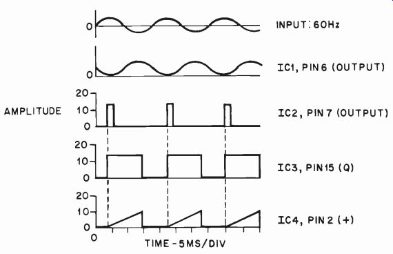
Fig. 3. Representative waveforms to be used in troubleshooting, with
S1 on X1, S2 open, S3 on +, S4 on NORMAL, R7 three-quarters CCW and the
timing capacitor selected for 1 ms/div.
The last problem can be reduced by first passing the blanking signal through one coupling capacitor to differentiate it and then diode clipping the unwanted half of the resulting waveform and finally connecting this signal to the Z-axis coupling capacitor.
A word of caution: In many scopes, the coupling capacitor is connected directly to the grid or cathode circuit of the CRT, which may be operating at 1000 or more volts. Do NOT attempt to bypass this capacitor or serious dam age will result. A coupling capacitor can be removed from the circuit only if it is not blocking a dc bias voltage.
Test and Calibration. Temporarily connect a 1-uF tantalum capacitor across the C_T terminals, observing polarity. Turn on the scope and adjust for a moderate-intensity dot in the middle of the screen. Apply power to the sweep circuit. Set S4 to AUTO; a horizontal base line trace should appear on the CRT and the TRIGGERED LED should come on. With this value of capacitor, the trace and LED indicator should flicker rapidly at the same rate.
If a trace does not appear, check the scope's BRIGHTNESS control and for + 15 volts on the trigger-sweep bus. Representative waveforms for troubleshooting are shown in Fig. 3. In this test, Si is set to X1, S2 is open, S3 is at +, S4 is set to NORMAL, R7 is three-quarters CCW, and CT is selected for 1 ms /division.
Using this setup, apply a 1-volt, 60-Hz sine-wave signal to the scope's vertical input. The sweep should automatically lock onto this signal and a steady display of three to four cycles should be seen on-screen. Check for any obvious nonlinearities. Rotate TRIG LEVEL control R7; the trace should disappear and reappear and the trigger level should vary up and down one side of the sine wave. Also note the change in the sensitivity of R7 when ATTENUATOR S1 is switched from X1 to X 10.
Center the scope trace and note its length. Before you can calibrate the sweep for a given time per unit length, overall length of the sweep must be set to a given repeatable value. (To ensure that the sweep is not inadvertently adjusted after calibration, the horizontal-gain control can be mounted inside the scope, or it can be replaced with a pair of fixed resistors.) Adjust the length of the trace to fill the screen. In some cases, the frequency response of the scope's horizontal amplifier may roll off at a lower frequency than those generated by this circuit at the highest sweep speeds, resulting in a shorter trace. You can compensate for this by setting the horizontal gain so that the trace is longer than the width of the screen at slow speeds. This will not affect accuracy at any speed, since each range is individually calibrated.
To calibrate the sweep, you need a source of reasonable-accuracy (1 % will do) square waves. A crystal-controlled timebase is ideal. You can also use a signal generator and frequency counter.
Before starting, wire the pc board terminals to the rotor connections of SWEEP SPEED selector S5, using a length of two-conductor cable that will be appropriate for the physical layout of your scope. It is important that you do this before calibration because the capacitance of the cable will be in parallel with the selected timing capacitors and at the highest sweep speeds will comprise a large portion of the timing capacitance.
Begin calibration at the highest sweep speed and work down. With the capacitance of the cable serving as the timing capacitor, feed a 1-MHz square wave to the scope's input. Adjust the trigger and scope controls for a stable, centered display. To obtain a stable display with low-bandwidth scopes, the vertical amplifier may have to be bypassed with the sweep circuit input connected directly to the signal source.
Experiment with several different capacitors connected to the switch until you find the value that produces a sweep speed closest to the desired 0.5 us/ division but not slower than this. That is, one cycle should occupy two divisions or slightly more. Unless you have a large number of capacitors on hand, you will find that the best way to obtain the exact capacitance value needed will be to parallel one capacitor with a lower-value capacitor until you obtain the desired display. Do your measuring between corresponding points in different cycles of the waveform. Do not, for example, measure between a rising and a falling edge of one cycle or of consecutive cycles. By following this rule, you will avoid errors introduced by asymmetry in the signal source and splaying or overshoot of the trace itself. For best results, choose two points separated by about six or eight divisions and equally spaced from the center line of the scope screen.
In the same manner, select the remaining timing capacitors, soldering them to the lugs of S5 as you proceed.
The next value should produce a 1-uS/ division sweep speed, then 2 µs/division, 5 As / division, etc., in the 1-2-5 format. For values larger than 0.5 AF or so, use high-quality tantalum capacitors and take care to observe polarity.
Operating Hints. The triggered-sweep circuit is very easy to use. For most applications, leave the input amplifier selector set to X 10 and set the mode switch to AUTO. Then set the number of cycles of the waveform you wish to view with SPEED selector S5. The period of any waveform can be obtained directly from the screen as the time it takes the beam to "write" one cycle, while the frequency is the reciprocal of this time.
Obtaining a stable display of a fraction of a repetitive waveform cycle is also easy. First, adjust the scope's vertical-gain, brightness, and centering controls for a stable display of several cycles. Set S4 to NORM and adjust R7 until the beginning of the portion of interest is at the left side of the screen.
Large-amplitude signals may drive IC1 into saturation, causing clipping and an apparent reduction in the range of the TRIG LEVEL control. If you cannot position the waveform properly, close Si to reduce the gain of the input op amp stage to unity.
Once the waveform is positioned, increase sweep speed until desired magnification is reached. Advance the brightness as necessary. When using very high-speed sweeps with relatively low-repetition-rate triggers, the scope beam and TRIGGERED LED will be very dim or appear to be off even when a sweep is present. This is due to the very low duty cycles in these situations.
As mentioned previously, bandwidth and/or noise limitations of the vertical amplifiers of some low-cost scopes may make triggering on high-frequency signals jittery at best or even impossible. In some of these cases (CMOS or TTL logic running in the low megahertz-range, for example), where signal amplitudes are in the 1-to-20-volt range and circuit loading tolerance is not too critical, the trigger signal can be routed directly to the input of the scope sweep circuit.
Another situation in which the best choice of trigger source is not immediately obvious occurs when you are looking for 60-Hz line noise. For example, if you are checking the output of a dc power supply with 1 or 2 mV of ripple, there will often be insufficient gain in the scope's vertical amplifier to yield a clean trigger pulse and the sweep will run free. However, since the ripple will occur exactly at the power-line frequency or a whole-number multiple thereof, syncing the sweep to the 60-Hz line will provide a rock-steady trace.
Providing a trigger-source selector switch that can disconnect the input of the sweep circuit from the vertical amplifier and connect it to an internal line-
voltage source simplifies sweep syncing. The pickoff point can be the secondary of any low-voltage transformer in your scope.
If you wish to gate an external device, such as an oscillator, in sync with the sweep generator, a CMOS-compatible signal is available at the Q output of IC3, which is at 0 volt during retrace and + 15 volts during sweep. The inverse of this is present at not-Q. In some applications, you may wish to sweep an external oscillator directly, using the sweep output of the circuit. Use a buffer amplifier if necessary to prevent excessive loading by low-impedance inputs.
Summing Up. By substituting the high performance triggered sweep described here for the recurrent sweep in an older scope, you can upgrade the instrument to permit better waveform analysis as needed for examining modern circuits.
Cost is modest and installation is fairly simple. It will also enable you to hold off on purchase of a costly modern scope for a while longer.