Source: Popular Electronics Electronic Experimenter's Handbook (1983)
BY FRANK WITNER AND DIANE JASINSKI
Save time and avoid possible circuit damage with little-known techniques of component testing.
IN-CIRCUIT measurement of a resistance offers several advantages compared to the alternative method of unsoldering one lead of the component to be measured. For example, it saves time and does not pose the risk of dam age to printed-circuit boards and the components mounted on them. Presented in this article are techniques that provide accurate in-circuit resistance measurements. These are not to be con fused with the use of so-called "low-power" ohmmeters that measure in-circuit resistance if the only shunting components are semiconductors. Rather, these techniques give accurate in-circuit resistance measurements even if the component to be measured is shunted by other resistors! Measurement Basics. If an ohm meter is used to measure the resistance of a component wired in a circuit, an inaccurate result will be obtained if there is any resistance in parallel with the resistance to be measured. Obviously, the parallel resistance causes a de crease in the overall resistance. The amount of error depends upon the ratio of the shunting circuit resistance to the value of the resistance to be measured. It is shown graphically in Fig. 1.
Seldom is a resistor in a given circuit placed directly in parallel with another resistor. Rather, any resistors connected to either side of it usually run to other circuit nodes. The delta-network model of a typical circuit shown in Fig. 2 reflects this. The resistor whose value is to be determined is designated RI, and the shunting circuit paths are embodied in R2 and R3.
The node at the junction of R2 and R3 makes it possible to electrically isolate the resistor to be measured without physically disconnecting one end of it.
This is accomplished by placing each end of part of the shunt path at the same voltage. Because there is no voltage drop across part of the shunt path, the entire shunt path behaves like an open circuit and will not affect an in-circuit resistance measurement of the component under test. This technique can be used even in a complex circuit because any number of shunt paths can be reduced to an equivalent of a single path by connecting together their junction points (homologous to the node R2R3).
There are several circuits, most of them designed around the operational amplifier, that can perform the required isolating function. Two of the qualities of the ideal operational amplifier make it well suited for this application. Firstly, no current flows into either the inverting or noninverting input terminals.
Secondly, in a noninverting amplifier with 100% feedback, there is no voltage difference between the inverting and noninverting inputs. These statements are true of ideal, not practical, operational amplifiers. However, contemporary practical op amps can, within certain limits, offer levels of performance closely approaching those of ideal amplifiers. The differences are then slight enough that they can be ignored.
The Voltage Follower shown in Fig. 3 can electrically isolate the resistance to be measured from the shunting circuit resistances in the following manner.
This stage has unity voltage gain and sets up at its output terminal the same voltage that appears at its noninverting input. When the ohmmeter is connected to the delta network as shown, a positive voltage appears at the HIGH TERMINAL and the follower's noninverting input.
The follower then sources current into R2 so that the node R2R3 is at the same voltage as the HIGH TERMINAL. There fore, no voltage drop appears across R3, and effectively no resistance is in parallel with 121, the component whose resistance is to be measured. This isolation causes the ohmmeter to provide an accurate resistance reading.
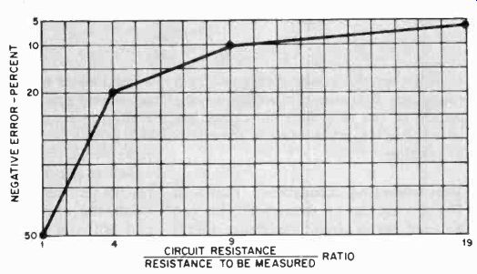
Fig. 1 Graphical analysis of the error in a resistance measurement caused
by uncompensated shunting circuit resistances.
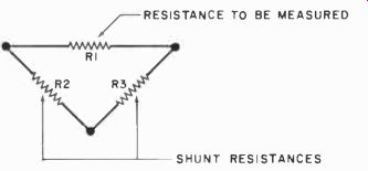
Fig. 2. Generalized model of a circuit containing a resistance to be
measured and shunting components.
Two factors determine how much current the follower must source through R2--the measuring potential impressed across the network by the ohmmeter and the value of the shunt resistance driven by the follower (in this case, R2). If the voltage impressed across the network by the ohmmeter is too high, the necessary current level might exceed the maxi mum amount of current the follower can safely provide or the heat generated by the driven shunt resistance might exceed the component's dissipation capability.
Reversing the follower leads might prove helpful if either of the problems just mentioned is expected to be encountered. This will cause the follower to source current into the other shunt element (R3), which might have a higher resistance. The best solution, however, is to use an ohmmeter that employs a low measuring potential. A moment's reflection on the familiar equation
P = E^2/R
reveals that the power dissipated by a resistance decreases according to the square of the reduction in voltage but only linearly to an increase in the resistance value.
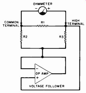
Fig. 3. Here, the voltage follower prevents shunting components from
influencing the ohmmeter reading.
The Inverting Amplifier shown in Fig. 4 is another op-amp circuit that can be used for in-circuit resistance measurement. One well-known property of the inverting amplifier is that its voltage gain equals the ratio of the feedback resistance to the input resistance. In the in-circuit measurement application shown in Fig. 4, the component whose resistance is to be determined (RI) functions as the feedback resistance.
Resistor R4 behaves as the stage's input resistance. If the input resistance is a stable, known value, the op amp's output voltage is proportional to the feedback resistance.
The inverting op amp can be used to measure an in-circuit resistance if the junction of the two shunt components (the node R2R3) is connected to ground.
A constant-current source drives the in put resistance, and the op amp sources current into R3 so that the same voltage appears across it as appears across R1, the resistance to be measured. Because of the feedback provided by R1, the HIGH TERMINAL is forced to virtually ground potential. Therefore, no voltage difference appears across shunt component R2, and the desired isolation of R1 is achieved.
If the amplitude of the driving constant-current source is accurately known, the voltmeter reading can be converted to a resistance measurement by simple arithmetic. Alternatively, if an analog meter is used along with a constant-current source of known out put, the meter's scale can be redrawn so that it reads directly in ohms. For resistance measurements over a wide range, it will probably be necessary to employ several meter scales and either a number of current sources with different output ratings or a single current source whose output can be varied in fixed, accurate increments.
Miller-effect analysis of this circuit reveals that resistances are reflected be tween the HIGH TERMINAL and ground and between the LOW TERMINAL and ground. These reflected resistances parallel shunt components R2 and R3 such that R2 is in parallel with a resistance equivalent to RI1(1-(11A)) and R3 is in parallel with a resistance equivalent to R11(1- A), where A is the voltage gain of the stage. The effective resistances of the shunt paths thus depend upon both the value of the component to be measured and the values of the shunt components-not upon the values of the shunt components alone. Because of the Miller effect, in a practical circuit, the operational amplifier can work with a lower value of shunt resistance between the LOW TERMINAL and ground than be tween the HIGH TERMINAL and ground.
Another inverting op-amp circuit that can be used for in-circuit resistance measurement appears in Fig. 5. Here, the resistance to be measured (R1) functions as the stage's input resistance and a constant-voltage source drives the network. The output voltage generated by the op amp is inversely proportional to the value of the component to be measured, and is monitored by a volt meter placed across the feedback resistor. As was the case in the previous circuit, feedback forces the HIGH TERMINAL to virtually ground potential. No voltage drop exists across R2, so the de sired isolation of RI is achieved. Shunt component R3 has no effect on the resistance measurement because it is connected directly across the constant-voltage source.
There are advantages that this inverting op-amp circuit has over the one previously presented. For example, the possibility exists in the constant-current case that the driven shunt resistance will be called upon to dissipate more heat than it is rated to do. This tends to be less of a problem when the constant-voltage circuit is employed. Also, the constant-voltage measuring circuit provides a faster response time when the resistance to be measured is shunted by one or more capacitors. The reason for this is simple. When a constant-current source is connected to a capacitive circuit, the voltage across the capacitor in creases linearly to its maximum value.
However, when a constant-voltage source is connected to an uncharged capacitor, the voltage across the capacitor increases exponentially until the capacitor is fully charged. This causes the capacitor to attain its ultimate voltage considerably faster than is the case when a constant-current source charges it, and allows for much shorter settling times during in-circuit resistance tests.
Bridge Measurements. A form of the classic Wagner bridge that can be used for in-circuit resistance measurements appears in Fig. 6. It can be thought of as two resistive bridges sharing common elements R7 and RI, which is the component whose value is to be measured. As was the case in the circuits presented earlier, R2 and R3 are the in-circuit shunting components.
Shunt resistor R3 is placed across the null meter when S1 is switched to its WAGNER position. This reduces the sensitivity of the null indicator for the Wagner adjustment but does not affect the balance of either bridge. Successive balancing of the bridge by means of potentiometers R4 and R6 (with S1 switched alternately to each of its positions) results in no voltage drop across R3, the non-driven shunt resistance.
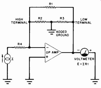
Fig. 4. An inverting op-amp circuit that can be used for in-circuit resistance
measurements.
Measurement of the unknown value of RI now depends on the balancing out of shunt resistance R3 such that the following relationship holds true:
RI/R7 = R2/R4 = R5/R6.
Note that this statement includes the standard balance equation of a four-arm resistive bridge.
An alternative bridge configuration has the side of potentiometer R4 that was formerly connected to the node R6R7BI- shifted to the node R5R6SI.
In effect, this is the same as interchanging the battery and the null detector in the bridge of Fig. 6. Measurement of RI now depends on the balancing out of shunt resistance R2 so that:
RI/RS = R3/R4 = R7/R6.
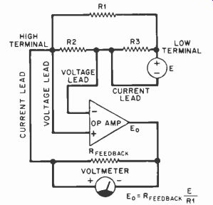
Fig. 5. Another inverting op-amp circuit where unknown resistance forms
amplifier's input resistor.
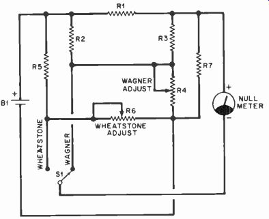
Fig. 6. A Wagner bridge circuit such as that shown here can be used to
measure resistance of an in-circuit component.
In this latter configuration, a voltage drop will appear across each shunt resistor when the bridge is balanced.
Practical Tips. A number of in-circuit measurement techniques have been presented in this article. However, there are several practical effects that should be 'considered before these techniques are implemented. These will now be summarized.
Thermoelectric voltages can be set up at the junctions of dissimilar conductors, as well as between points on the same conductor across which a thermal gradient exists. Although they are very small for ordinary working temperatures and materials commonly fabricated into probes and leads, these voltages can cause significant error if they are amplified as part of the measuring process. They can also be troublesome if the test potential of the ohmmeter is kept low to prevent semiconductor junctions from becoming forward-biased and influencing the reading. This type of error can be reduced by certain design techniques or by determining its magnitude and then subtracting it from the overall reading. The latter technique is commonly employed in precision, computerized procedures that are used to measure resistance.
If the measured resistance is of low value, test-lead resistance can be a source of significant error. The standard remedy for this is to use separate current-carrying and voltage-measuring leads. This avoids measurement 'of the IR drop in each current-carrying lead and is known as the Kelvin technique.
The in-circuit measurement techniques that have been presented can also eliminate the effects of semiconductors upon the resistance reading. However, any semiconductor present in the circuit might be called upon to dissipate power if it is part of the driven shunt path. Two practices are advised if this is the case.
In a constant-voltage circuit, employ a measuring voltage that is less than the conduction threshold of the pn junction.
In a constant-current circuit, reverse the polarity of the meter probes. These steps will effectively turn the semiconductor junction into an open circuit for the purposes of the resistance measurement and eliminate a source of potential error.
In measuring circuits containing an operational amplifier, certain precautions should be observed. It is wise to install 0.01-uF disc ceramic bypass capacitors close to the IC package from the positive and negative power-supply leads to ground. This will enhance circuit stability. Input overvoltage and out put short-circuit protection must also be considered. Many contemporary op amps, such as the Motorola MC1456, provide such protection internally. In those measurement situations which call upon the op amp to source more current into the driven shunt resistance than is available from the op amp, a current booster such as the Motorola MC1438R can be employed. Details on the use of the latter chip can be found in the manufacturer's Applications Handbook and its Linear Circuits Manual.