By STEVEN A. BROWN
Scrap the Mickey Mouse talk from the high-end CB channels by building this Beat Frequency Oscillator for your rig. The clarity of the detected SSB signals is great!
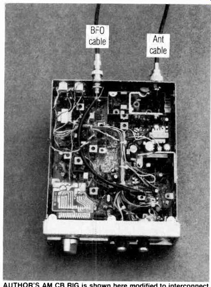
------- AUTHOR'S AM CB RIG is shown here modified to interconnect
with his BFO unit via a RG-58/U coaxial cable.
IF YOU OWN AN AM CB RADIO, YOU HAVE PROBABLY heard the garbled, unintelligible noises being transmitted on the upper half-dozen or so channels at one time or another. Those transmissions are designated single-sideband suppressed-carrier, or simply SSB, and the rigs designed to transmit and receive such signals are necessarily more complex and expensive than their ordinary AM counterparts. If budgetary considerations have kept you from investing in one of those high-priced sets, here is a simple. low-cost circuit that will make it possible for you to monitor SSB transmissions on your AM rig. It will not make it possible for you to transmit SSB, but you will be able to hear the incredible DX that prevails during the daylight hours on the Citizens Band, made possible by the combination of SSB's inherent power efficiency and narrow bandwidth.
How it works
Before examining the circuit, let's briefly review what SSB is. An AM, or amplitude-modulated, transmission consists of a continuous carrier whose amplitude, or strength, is modulated, or made to vary, according to the audio signal. At 100% modulation, the carrier rises to twice its normal amplitude and falls to zero amplitude, at a rate equal to the modulating frequency. Ideally, the audio power needed to cause 100% modulation is equal to one-half the power of the carrier.
That audio power is converted to RF power and is radiated by the antenna as additional energy. A 10-watt carrier that is modulated 100% results in as much as 15 watts of total RF power. The additional 5 watts appears as upper and lower sidebands, one above and one below the carrier.
Each sideband is removed from the carrier frequency by an amount equal to the modulating frequency. The sidebands are mirror images of each other, and both contain the same information. Since the carrier contains no information, at least 83% of the power in an AM transmission (66.7% for the carrier and 16.7% for one sideband) is either redundant or unnecessary for the transmission of information. By eliminating the carrier in a balanced modulator and filtering out one of the sidebands, a 2.5-watt SSB transmitter could have an output comparable to that of a 10-watt AM transmitter.
At the receiving end, an oscillator, known as a beat-frequency oscillator, or BFO, is used to insert the missing carrier prior to detection, to re-create the original audio frequencies by heterodyning, or "beating," the sideband frequencies against the oscillator frequency. To monitor SSB transmissions on an AM CB radio, the only additional piece of equipment you need is the BFO presented here.
It is convenient to have the beat-frequency oscillator tuned to the receiver's IF, or intermediate frequency.
Since all incoming signals are converted to this one frequency, usually 455 kHz, the BFO's design is simplified and stability improved by not having to be tuned more than a few hundred Hertz above or below that frequency. The complete schematic of this BFO is in Fig. 1. The one the author built is a Hartley oscillator, modified so that one side of the LC circuit is grounded.
That makes it possible to use a tuning capacitor (C3) whose rotor plates are grounded to the chassis.
The inductance (L) of the tuned circuit is the tapped primary winding of transformer T1, while the capacitance consists of capacitor C l in parallel with the series combination C2, C3, and C10. The active device in the oscillator stage is transistor Q2, with Q1 used as a voltage regulator for Q2. At turn-on, Q2 is biased into conduction by voltage divider R1-R2, causing a surge of emitter current to flow through the lower section of the primary winding of T1, from ground to pin 5. That sets up an expanding magnetic field that excites the LC circuit into oscillation. The top of the LC circuit, at pin 2 of T1, is RF coupled by C6 to Q2's base, controlling the transistor's conduction so that it varies in accordance with the oscillations. The varying emitter current of Q2 causes magnetic fluctuations in T1 that are in phase with the oscillating magnetic field, thereby providing enough energy to the circuit to overcome losses and maintain continuous oscillation.
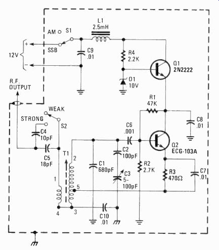
FIG. 1--COMPLETE SCHEMATIC DIAGRAM OF THE BFO. 12-volt supply can be tapped
from CB rig; otherwise batteries may be used. Do not confuse case ground
from circuit ground-they are not common. C10 connects those grounds together.
A BFO must be stable, since any drift in operating frequency will cause a corresponding drift in the voice frequencies being received. That can make a human voice sound unnaturally deep or unnaturally high. The two methods used in this circuit to provide stability are the high value of capacitance in the tuned circuit (approximately 900 pF) and a well-regulated supply voltage for the oscillating stage.
A high C-to-L ratio in the tuned circuit minimizes the effect of varying stray capacitance, such as those caused by thermal component expansion and hand capacitance. The latter effect is further reduced by enclosing the entire circuit in a grounded metal case.
Zener diode D1 , together with R4, and Q1 provides the needed regulation. The constant, nonvarying drop of 10 volts across D1 is coupled to the base of Q1, an emitter-follower current amplifier. Any tendency for the emitter voltage to change, alters the bias on Q1, forcing the transistor to compensate by conducting more or less. That holds the emitter to a constant +9.4 volts. RF choke L1 together with C9 forms a low-pass filter that prevents RF energy from escaping from the shielded enclosure via the positive power supply line.
That is vital. It protects against harmonic or parasitic oscillations generated in the 27-MHz region, as well as the pickup of the fundamental frequency itself, that could cause interference by being capacitively coupled through the receiver's RF and mixer stages to the IF strip, where it would be greatly amplified.
When you check out the schematic diagram (Fig. 1) you will see that there are two grounds, circuit board ground and chassis ground. They are RF coupled to each other by C10. That setup isolates the negative supply line from the chassis, so the BFO can be used in vehicles with positive-ground electrical systems, provided that the chassis of the CB is also isolated from the circuit board ground.
The oscillator coil is the tapped primary winding of a 455-kHz slug-tuned IF transformer. The low-impedance secondary winding couples RF energy through C4 and C5 to the final IF stage in the CB receiver. That loose, indirect coupling minimizes any interaction between the receiver and the BFO, further assuring oscillator stability. Closing S2 shunts C4 in parallel with C5, increasing the amount of coupling capacitance, which is desirable when receiving strong SSB signals. The switch is left open to receive normal and weak signals.
By matching the degree of BFO coupling to the strength of the incoming signal, optimum receiver sensitivity is maintained.
A loose coupling to the BFO for weak signals allows the automatic volume control to set maximum gain. A tighter coupling increases the BFO signal, causing the AVC to reduce the gain. A strong SSB signal, however, requires a strong BFO signal to maintain optimum clarity. The gain reduction caused by throwing S2 to the STRONG position effectively reduces the volume blast that accompanies the sudden appearance of a strong signal with the receiver gain turned to a high setting.
Transformer T1's primary is shunted by an internal 180-pF capacitor, not shown in the schematic diagram (Fig. 1), and if C1 were removed from the circuit, the oscillator could be tuned to a fundamental frequency of 455 kHz. However, stability would not be quite good enough, because of the small amount of capacitance in the circuit. For that reason, 680 pF of capacitance was added to the tuned circuit. This makes it resonant at 227.5 kHz, exactly half the 455-kHz IF frequency.
The BFO's output is coupled to the input of the final IF stage in the CB receiver. Since the collector load of this stage is a 455-kHz tuned transformer, the amplified BFO signal excites the LC circuit into oscillation at its resonant frequency. In that way the final IF stage in the receiver serves as a frequency-doubler for the BFO. The second harmonic of the BFO, at 455 kHz, is also amplified by the final IF stage and reinforces the oscillations. C1 should have a tolerance of 10% or better to ensure that the intended operating frequency falls within the slug-tuning range of T1. The desirable range of tuning after T1 has been adjusted, is only a few hundred Hertz above and below that frequency, to allow for the frequency tolerance of SSB transmitters. A range of approximately 2.5 to 50 pF has been found optimal for a tuning capacitor across the LC circuit. That is the effective capacitance range of C2 and C3 in series.
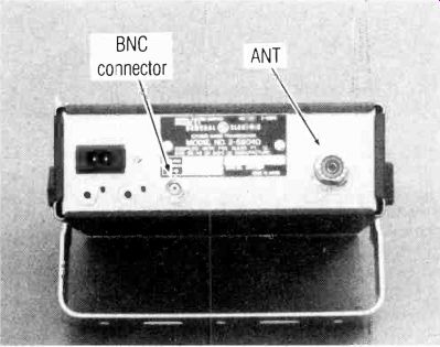
------ BNC CONNECTOR ON BACK PANEL may be left unconnected when
the BFO is not used. Note that it adds no extra depth.
--------- ALL HOOKED UP AND READY TO GO! Here's what your CB rig
may look like after the BFO has been fitted to the CB.
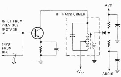
FIG. 2--SIMPLE HOOK-UP SCHEMATIC DIAGRAM illustrating where to couple signal
from the CB second IF to the BFO. Fig. 2 shows how to couple the BFO
to the CB receiver. Use a length of 52-ohm coaxial cable, the outer conductor
connected to chassis ground at both ends, to conduct the BFO signal into
the transceiver. At the transceiver, connect the inner conductor directly
to the base lead of the final IF amplifier transistor. This stage amplifies
both IF and BFO frequencies, which are then heterodyned against each
other in the diode detector following this stage, to develop AVC and audio
signals.
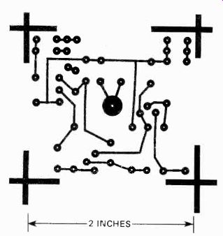
FIG. 3--FOIL SIDE OF THE PC BOARD. Parts list gives details on purchasing
an etched, drilled and tinned board.
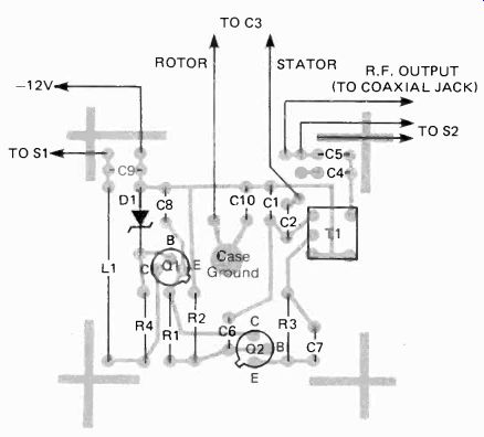
FIG. 4--COMPONENT PLACEMENT GUIDE for the printed-circuit board. Large
copper circle in center of board electrically connects to case ground
through the mounting hardware. Refer to text for details.
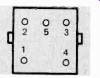
FIG. 5--PIN LOCATION DIAGRAM FOR THE IF TRANSFORMER, T1-bottom view.
Now put it all together
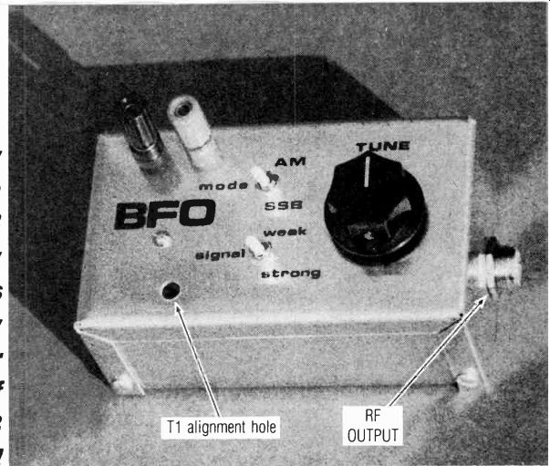
The entire BFO circuit must be completely contained inside a shielded metal enclosure. An aluminum mini-box makes an ideal case. To simplify construction, all components are mounted inside the top cover, as you can see in the photographs. The prototype uses a printed circuit board, although point-to-point wiring on a perf board will work just as well. Since the circuit board measures only 2-inches by 1.75-inches, a 1-inch 6-32 machine screw, fastened to the top cover of the chassis with a hex nut, acts as the single mounting stud located in the center of the board. The board itself is secured by two No. 6 hex nuts, one above and one below the board.
Position the board near the end of the stud, so the top of T1 lies about 1/4-inch below the top cover of the enclosure. To protect the copper foil on the printed circuit board, position a No. 6 flat brass washer between the foil side of the board and the lower mounting nut. Coat the large circular pad around the mounting stud with a thin layer of solder to assure good electrical contact. That stud also provides the connection between chassis ground and the pads on the printed circuit board for C 10 and tuning capacitor C3. Connect C3's rotor plates to chassis ground by one of these pads, unless C3 is a variable capacitor whose rotor plates are grounded by the mounting screws. In either case, use a piece of hookup wire to connect the stator plates to the appropriate pad on the printed circuit board (see Fig. 3). In the schematic diagram (Fig. 1) C3 is a 5-100-pF air trimmer capacitor, but any variable capacitor whose maximum capacitance is at least 50 pF may be used provided you change the value of C2 so that the maximum capacitance of C2 and C3 in series is 50 pF. If the maximum capacitance of C3 is 50 pF, substitute a piece of jumper wire for C2. For any maximum value of C3 greater than 50 pF, use the following rearrangement of the series capacitance formula to determine the value in pF for C2: C2-1 0.02-1/C3 where C3 equals the maximum value in picofarads of the variable capacitor. If C3 were a standard 16-365 pF tuning capacitor, the value of C2 computed from the formula would be 57.9 pF. A 56-pF ceramic disc capacitor could be used.
Carefully position a 1/4-inch hole in the top cover directly over T1, so you can adjust its tuning slug with a small screwdriver. Two insulated binding posts, one red and one black, are used as positive and negative power supply input terminals. The positive terminal connects to the printed circuit board via MODE switch S1, which functions as an on-off switch.
Mount an SO-239 coaxial jack in a 1/4-inch hole in the right end of the top cover. That is the output terminal.
Connect the inner conductor via a piece of hookup wire to the RF output pad on the printed circuit board.
The easiest way to wire the board to the other components on the chassis is to solder pieces of hookup wire longer than needed to the board. Then position the board on the mounting stud and run the wires out to the switches, connectors, and trimmer, and cut to the appropriate length. Strip the ends of the wires before fastening the board to the mounting stud.
Use an 18-inch length of RG-58/U coaxial cable to couple the BFO to the CB. Attach a PL-259 plug at one end, for connection to the jack on the BFO. At the other end attach a type UG-88 male BNC connector, that will connect to a type 1094 female BNC connector mounted in a 5/16-inch hole drilled into the back plate of the CB chassis. Remove the top and bottom covers from the transceiver, and install that jack in a place that will provide enough clearance to make the necessary connections.
After installing the jack, refer to the schematic diagram of your transceiver. Determine which transistor is the final IF amplifier. That should be easy because there are usually only two IF stages, clearly labeled in the schematic diagram. The final IF stage is the one whose output transformer's secondary goes to the diode detector for audio and AVC (see Fig. 2). If you do not have a schematic diagram of your CB rig, look on the circuit board for an IF transformer, usually near the front of the set, near the audio circuitry, that has a germanium glass diode right next to it. That diode is connected to one of the secondary pins of the IF transformer. You can verify this with an ohmmeter. The transistor whose collector goes to the primary of that transformer is the final IF stage.
Carefully solder a piece of hookup wire to the base lead of this transistor, preferably on the underside of the board, and run that wire as directly as possible to the top side of the board. Now measure out and cut a length of RG-58/U coaxial cable to extend from the female BNC connector at the back of the CB set to that piece of hookup wire. Strip both ends, exposing the inner conductor at one end and both inner and outer conductors at the other end. Solder the end with both conductors exposed to the BNC connector, connecting the outer conductor to the chassis. Clip off any length of outer conductor that may be exposed at the other end, and solder the inner conductor to the piece of hookup wire. Wrap that end completely with electrical tape, covering any part of the outer conductor that may still be exposed.
------------
PARTS LIST:
RESISTORS
1/4 watt, 5% or better
R1-47,000 ohms
R2-2,700 ohms
R3-470 ohms
R4-2,200 ohms
CAPACITORS
20% or better unless otherwise specified
C1-680 pF, 10% ceramic
C2-100 pF ceramic
C3-5-100 pF air variable, or other (see text)
C4-10 pF ceramic
C5-18 pF ceramic
C6-1000 pF ceramic
C7, C8, C9, C10-0.01 uF ceramic
SEMICONDUCTORS
D1-10-volt Zener diode (1N5240B, 1N961 B, 1N758A or equal)
Q1-2N2222, 2N3904 or similar NPN general purpose
Q2-ECG-103A, SK3010, or GE-59 NPN germanium
OTHER COMPONENTS
L1-2.5-mH miniature RF choke (J.W. Miller 70F253A1 or equal)
T1-455-kHz miniature slug-tuned IF transformer (J.W. Miller 8535 or equal)
S1, S2-subminiature SPST toggle switch
MISCELLANEOUS
5 ¼” x 3" x 2 1/8" aluminum Minibox (Radio-Shack 270-238 or equal)
2 insulated binding posts
SO-239 chassis or bulkhead coaxial jack
PL-259 coaxial plug UG-88 male
BNC plug 1094 female BNC jack 24 inches of RG-58/U coaxial cable plastic tuning knob 1-inch No. 6 machine screw 3 No. 6 hex nuts No. 6 flat brass washer hookup wire solder The following items are available from: Andromeda Electronics, 89 Timberbrook Rd., Marcella, N.J. 07866: No. BFO-1-PC board only, etched, drilled, tinned, $3.50 postpaid.
No. BFO-1T-PC board plus J.W. Miller #8535 455 kHz IF transformer, $10.00 postpaid.
No. BFO-1K-Complete kit of all parts, including pre-drilled enclosure, air trimmer, coaxial cable and connectors, all hardware except wire and solder, $34.95 plus $2.50 shipping and handling.
No. BFO-2-Assefnbled and tested unit, with coaxial cable and connectors, $44.95 plus $2.50 shipping and handling. N.J. residents, please add 5% sales tax.
------------
If your transceiver is a base-station model with its own internal power supply, you may wish to connect leads to the board ground and + Vcc, to be led outside to power the BFO, if you do not already have a separate 12-volt power supply.
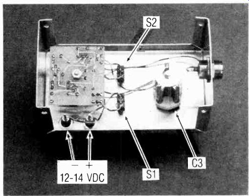
------- INSIDE THE BFO there's lots of space in the author's
recommended chassis box. You could use a smaller box.
For mobile use, mount the BFO directly onto the bottom cover of the transceiver with two 3/8-inch No. 8 sheet metal screws. Remove the bottom cover from the CB and drill two 3/16-inch holes about 1 1/4-inches from the front edge. Align those holes with two holes drilled into the back of the BFO enclosure. They should be 1/a-inch diameter for proper fastening by the sheet metal screws. If desired, an additional hole can be drilled through both covers to allow the passage of power supply leads from the BFO into the CB, thus eliminating the need for external binding posts. Simply run those wires to the power connector terminals inside the CB. Be sure to install grommets in these holes.
Alignment and operation Adjust C3 so that the plates are half-meshed, and turn the slug in T1 counter-clockwise until it reaches the top of the can. Connect the BFO to your CB with the coaxial cable, and connect the power supply terminals to a source of 12 VDC. Disconnect the CB antenna.
Turn the CB on, set S1 to the SSB position, and set S2 to the WEAK position. Watch the signal-strength meter on the CB while gradually turning the slug in T1 clockwise. As the second harmonic of the BFO approaches 455 kHz, the S-meter should gradually rise. "Peak" the oscillator for a maximum reading on the meter, which should be about "S2" or "S3". If you can't obtain a reading, make sure the BFO is oscillating by throwing S2 to the STRONG position, disconnecting the coax from the CB, and touching the inner conductor to a few feet of wire placed near an AM broadcast receiver tuned to a clear frequency. Again turn T1's slug in and out, being careful not to force it beyond its limits of travel. The receiver should become quiet as you tune a harmonic of the oscillator through the frequency to which the receiver is tuned. If the BFO is not oscillating, check your wiring and the positioning of T1, Q1, Q2, and D1 . Make sure that D1's anode goes to ground. Check the coax for continuity and for shorts caused by improper installation of the coaxial plugs. If the circuit is oscillating, go back and make sure you have coupled the BFO signal to the proper lead of the proper stage in the CB. If everything is working properly, turn the BFO off (S1 to the AM position) and re-connect the antenna to the CB. Turn the CB on and listen to the upper channels starting at 40 and proceeding downward, until you hear a SSB transmission. It will be recognized as a garbled noise, with the S-meter rising and falling in accordance with the strength of the noise. Turn the BFO on, and carefully adjust T1 until you can recognize a voice close to normal pitch. If the signal is very strong, you may need to throw S1 to the STRONG position. C3 can now be used to fine tune for natural voice quality. Adjust T l so that C3 tunes to the center of the channel with its plates half-meshed. Thereafter, T1 should not require any further adjustment. Using C3, you will be able to separate one station from another on the same channel.
Since not all CB transceivers are identical, the BFO signal strength may vary--from its optimum value. With S2 in the "weak" position, the BFO should cause the S-meter to hold steady at "S2" or "S3", with no signal being received or the antenna disconnected. In the STRONG position, the meter should read about "S7". Any significant departure from these readings can be remedied by varying values of C4 and C5. SP.