By HERB FRIEDMAN
Let this simple RF oscillator circuit pulsed by a crystal spot the place on the dial of your next SW DX
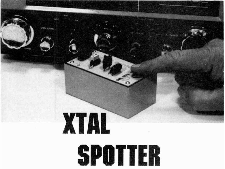
IS YOUR SHORTWAVE RECEIVER ONE OF THE NEW DIGITAL TYPES with "computer accuracy" so good that you can preset the dial to a station's frequency and be "right on the money" when the power is first turned on? If not, there's a good chance that you can probably add a great deal of pleasure to your shortwave listening with an Xtal Spotter.
The Xtal Spotter uses a crystal-controlled oscillator to provide an accurate marker for receivers that are not equipped with precision dial calibration. It allows the user to preset the main or bandspread tuning dial directly to the frequency of a desired shortwave station, even when the station is not on the air.
Until the era of the digital receiver, both inexpensive and "gold plated" shortwave and communication receivers had dial calibrations whose accuracy ranged from "close" to "only heaven knows." Locating a desired station either took a bit of fiddling with the dials or an external precision-calibrated frequency generator (freq-meter) or a quality ham VFO. The user set the frequency generator to the desired frequency and then tuned the receiver until the signal was heard.
Hams who couldn't stretch the budget for a freq-meter often simply tuned in the signal for their transmitter's crystal-controlled oscillator. They would set the bandspread to the known frequency and then rock the main tuning until they heard the signal, thereby calibrating the main and bandspread dials for a given band. Naturally, SWL's didn't have a crystal-controlled transmitter to provide a reference frequency, so finding a signal-even when the frequency was known-often was hit-or-miss.
One inexpensive idea that worked well when there were only a few "important" frequencies to monitor was the crystal controlled spotting oscillator, or Xtal Spotter as it's more frequently called. That is simply a very low power crystal oscillator that provides a marker for the receiver. The user keys the spotter and simply tunes the receiver until the signal is found.
Inside the circuit
The unit shown in the photographs is a modern version of the Xtal Spotter specifically intended to be built from junk-box parts and designed for SWL use between about 1.5 and 30 MHz. Most everything should be found lying around your shop. All you should need to buy are the crystals (and perhaps their sockets), and later we'll tell you where to get them at rock-bottom cost, usually between $2.50 and $4.
If you examine the schematic diagram in Fig. 1, you can probably think of several ways to improve the circuit.
However, the circuit shown will work with just about every type of crystal you're likely to come across, regardless of the tolerance of the components used. Basically, the circuit is designed to insure that the oscillator will "start" with every type of crystal when power switch Si is depressed. You can use "fundamental" crystals, or the "overtone" type; they will all start. The actual output frequency might be off a few Hz from the specified value, but you'll at least be "on frequency" regardless what crystal you use.
The test point labeled TP in Fig. 1 provides a small output sample for driving a frequency counter, just in case you want to check the precise output frequency.
---------
PARTS LIST
Resistors are 1/2-watt, 10% unless otherwise noted
R1-270,000 ohms
R2-1000 ohms
Connectors
C1-68-pF 5% mica
C2-1000-pF 5% mica
C3-470-pF
C4-0.01 µF
Miscellaneous
Q1-NPN transistor, 2N3391.
S1-Normally-open pushbutton switch
B1-9-volt transistor battery
S01-FT-243 crystal socket, JAN SSO-1, see text.
S02-HC25/U crystal socket, JAN CE-25, see text.
Cabinet, hardware wire, solder etc.
Note. Crystal sockets and crystals are available from JAN Crystals, 2400 Crystal Drive, FT. Myers, FL 33906. Send for free catalog before you order.
----------
----------
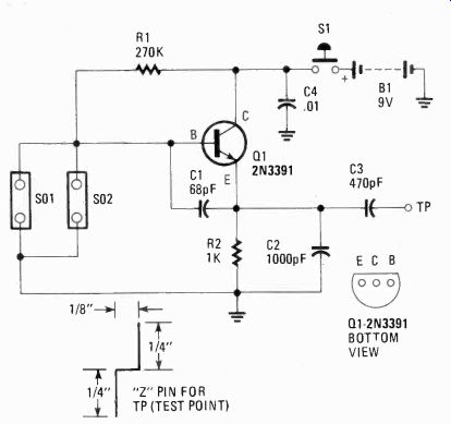
Fig. 1. SCHEMATIC DIAGRAM FOR XTAL SPOTTER uses a 250 h10 minimum transistor. Two or more crystal sockets may be installed on the project, however, only one crystal at a time may be used in the circuit. Keep the project construction neat and clean, and there should be no problems during the first test.
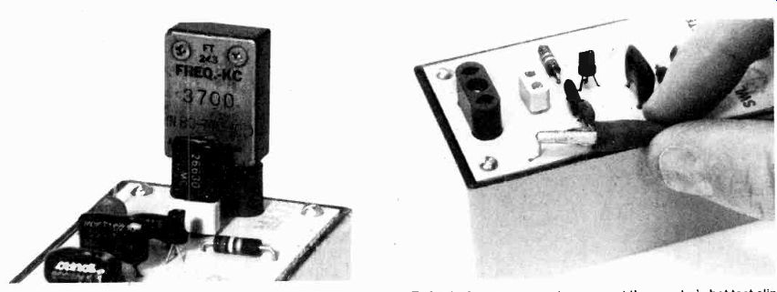
---- Sockets can be provided to accommodate two or more of the standard crystal holders, as shown. Naturally, you can't use two crystals at once; we plugged in two just to illustrate how the standard FT-243 and HC25/U crystals fit on the board.
---- To feed a frequency counter, connect the counter's hot test clip to the Z pin test point (TP) and the ground test clip to the ground end of resistor R2. Insert a crystal into either socket, depress S1, on Xtal Spotter and let the frequency counter do all the rest!
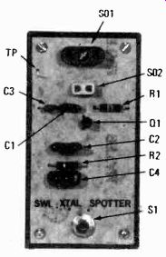
------------ The entire Xtal Spotter project is assembled on a small printed-circuit board that also serves as the cover for the cabinet. Note that there's more than enough room to add another crystal socket or more if needed.
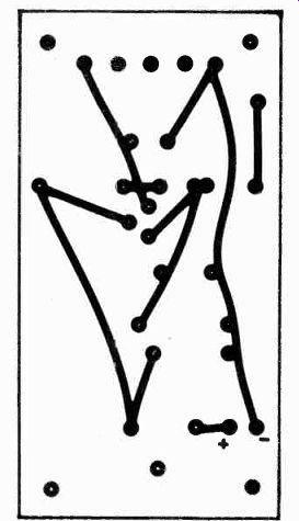
----------- Fig. 2. CIRCUIT-BOARD TEMPLATE is shown here foil-side up and exact size. The circuit board serves as the unit's cover with all component parts except for the clip-on transistor battery.
Tips on Xtals
A quick note about overtone crystals: They oscillate at approximately one-third or one-fifth the specified frequency.
Third overtone crystals were commonly used for CB. We say "approximately" because they provide the specified output frequency only when used in an "overtone-type" oscillator circuit. Used in a "standard" oscillator circuit they tend to oscillate a few hundred Hz below the calculated "base" frequency.
The least expensive crystals are military surplus. There's not too much of a demand for crystals in "large" holders, such as the FT-243, and you can often pick them up two-for-$1. Though they might be some 30 years old (or more) they are still good, and certainly worth the price.
If you can't find what you want as a surplus you can order crystals cut to your frequency from JAN Crystals, 2400 Crystal Drive, Fort Myers, FL 33906. Their crystals are available in various holders: HC6/U, HC25/U, HC18/U, H 17/U, HC33/U and FT-243. They even sell the crystal sockets at rock-bottom prices. The two used in this article are available from JAN Crystals for 20 cents and 30 cents; that's even less than Radio Shack charges for a pack of resistors.
JAN Crystals has so many different crystals and holders available that you must have their catalog before placing an order.
Construction
The Xtal Spotter is built on a printed-circuit board that also serves as the cover for a plastic experimenter's cabinet approximately 2 1/2 x 1 5/8 x 4 inches. A full scale template of the foil layout is provided in Fig. 2. Any substitute for the specified transistor should work as long as the hfe is at least 250. Capacitors C1 and C2 should be 5% mica; C3 and C4 can be anything: mica, ceramic, poly, etc.
Sockets SO1 and SO1 match the crystal types that you plan to use. If you only use one type of crystal, simply eliminate one socket. In the model shown, sockets for the FT-243 and HC25/U crystals were provided because they are the types most frequently used or found surplus.
Any normal-open pushbutton switch can be used for power-switch S1. Battery B1 is a standard 9-volt transistor-radio type battery, which is secured by a small holder inside the cabinet. Since the current drain is only about 5 mA when operating, a standard carbon-zinc battery should last almost its shelf life.
The test point, labeled TP, is a small Z pin fashioned from #20 wire or a wire-wrap terminal. The Z shape is suggested only because it has a little extra support for the small alligator clip of a frequency-counter's test cable.
Checkout
Connect a 0-10 DC mA meter in series with one battery connection, and without a crystal installed, depress Si, and note the current reading--which should be in the range of 4 to 6 mA. While holding S1 down, insert a known good crystal.
If the unit breaks into oscillation, the current will rise approximately 0.5 to 1 mA. If there is absolutely no rise in current, check for a wiring error.
Using the Spotter
Set a shortwave receiver to the correct band and approximate crystal frequency. Set the receiver's BFO to on, or set the AM/SSB selector to SSB so the BFO is on. Place the spotter near the receiver, preferably on top towards the antenna connection, and depress S1. While holding S1 on, tune the receiver until you hear the heterodyne (whistle) caused by the bfo beating against the Xtal Spotter's output. Key S1 on and off a few times so you're certain that the beat you're hearing belongs to the spotter and not a SW station.
Counter connection If you want to check the Xtal Spotter's frequency with a counter, set the counter to maximum sensitivity, connect the counter's ground test clip to the "ground" end of resistor R2 (nearest the edge of the PC board), and clip the counter's "hot" test clip to TP. Note that the spotter's output level is designed for the lowest possible value that will provide a dependable marker. It is not, by any means intended to overwhelm the receiver input, so connecting a wire "antenna" to test point TP will have virtually no affect on the Xtal Spotter's signal level. SP.