by HERB FRIEDMAN
Turn off your burglar alarm bell automatically after it drove off the uninvited intruder and before it drives your neighbor nuts!
BURGLARY AND ALARM SYSTEMS GO HAND IN HAND. the more burglaries there are, the more alarms there are, and the more racket there is as bells, sirens, and klaxons ring for seemingly endless hours.
In fact, the noise from alarm systems is getting so bad that many cities and towns now have ordinances that restrict sharply how long an alarm can sound off before the homeowner is hit with a fine for disturbing the peace.
Because all but the most recent alarm systems did not have a Cut-Off Timer for the bell or siren (and many new models still don't have a cut-off) the first inkling a homeowner often has of the new laws is when a policeman comes by to hand out a summons because the alarm sounded through the day or weekend-long after the alarm had done the job of scaring off the burglar.
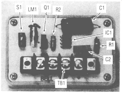
Adding a Cut-Off-Timer to most home burglar-alarm systems is relatively easy because all you need is an accessory add-on device that will silence the alarm after 10, 20, or 30 minutes, even though the alarm is still locked "on." Just such an accessory timing device for 6- or 12-volt DC alarm systems is shown in the photographs. Assembled on a small printed-circuit board, the device is spliced into the alarm system's bell, klaxon, or DC siren-control wires. It's easy; no modification has to be made to the alarm's existing control-box circuit.
When the alarm is triggered, the Cut-Off Timer permits the alarm bell (or whatever) to ring. After a predetermined period, selected by the user, the timer turns off the DC current to the bell. Reset is automatic. Any time the alarm is turned on from an off condition the timer resets.
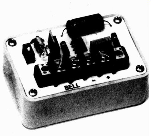
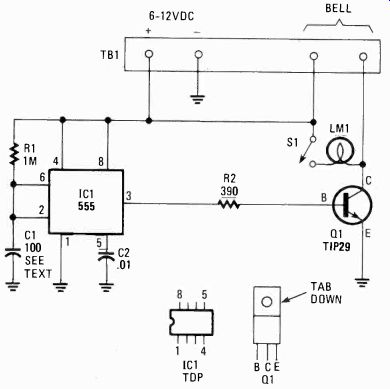
---- THE CUT-OFF TIMER IS BUILT on a printed-circuit board that
also simpler. Timing is automatically reset to zero after power is turned
off, and begins to count when power is applied. Transistor Gil does the
heavy-duty power switching.
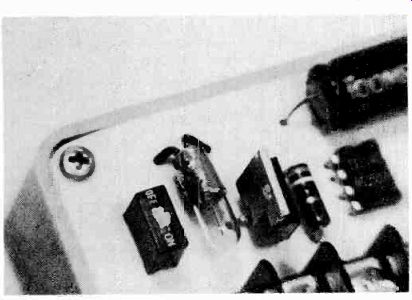
----------- THE SMALL PILOT LAMP and the printed-circuit switch form
a test circuit that permits the system to be tested without sounding
the alarm bell. They can be eliminated if you want to cut costs.
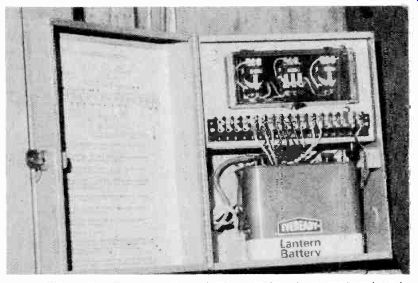
------- THE TIMER IS CONNECTED into the burglar alarm at the alarm's
terminal strip. Most professional alarm systems use a terminal strip rather
than direct splicing into the wiring, or soldering.
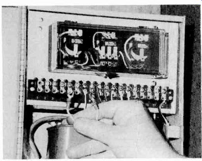
------ REMOVE THE EXISTING BELL CONNECTIONS from the alarm's terminal
strip. The alarm terminals will be used to power the timer. The bell
connections are moved to the timer. Use a VOM to determine which of the
alarm's bell connections is "positive."
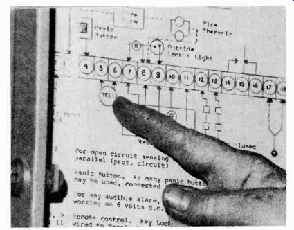
-------- IF YOU CAN'T IDENTIFY the alarm's bell terminals by eyeballing
the wiring look for a wiring schematic diagram. Usually it's inside the
cover or door, but it can also be concealed behind the backup battery
or power supply compartment.
The timing control is the easily-obtained 555. If you're looking for a negative-going trigger-pulse to start the timer, look no farther because there is none. The 555 timer circuit used in this project triggers itself on a--cold start" or "power up"; it does not need a negative pulse to trigger. The alarm bell will sound instantly when the alarm system is "tripped" because IC1 turns on Q1, which in turn permits the alarm bell to sound off.
The 555 turns off at the end of the time period determined by R1 and C1, thereby turning off Q1 and the power supply for the bell.
A few words about R1 and C1. The standard timing formula for the 555 is: "Time in Seconds = 1.1 x R1 x C1." Theoretically, that is correct-at least for the components used for time delay in the millisecond range. Unfortunately, that is not true when using large capacitors needed for timing that extends beyond a few minutes. The inherent leakage in inexpensive large-capacity electrolytic capacitors throws off all calculations, and best results are obtained through trial and error. Also, to keep leakage effects to a minimum, R1 should be no larger than 1-megohm-even though a larger size is usually permitted for the 555.
As a general rule of thumb for 12-volt alarm systems: with a 1-megohm resistor for R1, a 10-minute delay will be obtained if C1 is one of those "real cheap" 100-uF electrolytic capacitors that's usually sold to hobbyists.
The problem of capacitor leakage is magnified at a lower-circuit voltage. If your alarm system is powered by 6-volts DC, try a capacitor of about 30 µF-they often will product a 5- to 10-minute alarm period.
A test circuit consisting of lamp LM1 and DIP switch S1 is provided so you can test the alarm's timing without sounding the alarm bell. When one alarm bell wire is disconnected and S1 is on the glow of the lamp substitutes for the ringing of the bell. When you're certain that everything works to perfection, simply set S1 to off-thereby disconnecting lamp LM1--and re-connect the bell to the terminals.
Construction
The Cut-Off Timer is assembled on a printed-circuit board that also serves as a cover for a 1 1/8 x 3 1/4 x 2 1/8 inch "Mini" Utility Box (Radio Shack 270-230). An "extra" set of component mounting-holes for C1 is provided so you can use either coaxial or "end mount" (Printed Circuit) capacitors. Nothing is critical, and you can make any changes you'd like.
The component holes are drilled with a No. 55 or No. 56 bit. The terminal block's PC connections require a No. 46 or No. 47 bit. Though drill centers are indicated for the terminal strip's mounting screws, actually the strip is firmly secured when the terminal lugs are soldered to the PC foil pads.
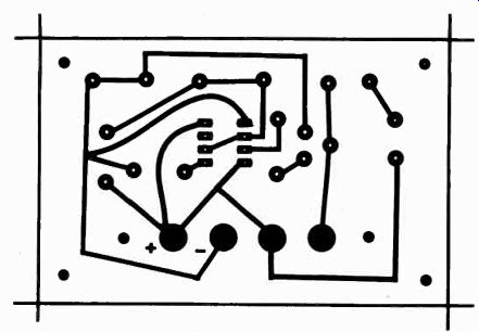
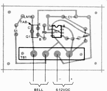
FIGS. 2 & 3 ABOVE illustrate the same size foil pattern with the foil
side up (Fig. 2) left and foil side down (Fig. 3) right with circuit parts
matched with the printed-circuit board holes. If a photo is more helpful,
look below for parts placement information.
--------- PARTS LIST
RESISTORS
R1-1-megohm, 1/2 watt
R2-390 ohms, 1/2 watt, see text
CAPACTORS
C1-100-uF/15V electrolytic capacitor, see text
C2-0.01-uF ceramic disc capacitor (or Mylar)
SEMICONDUCTORS
IC1-Integrated circuit, type 555 timer
Q1-NPN silicon switching transistor, TIP29 or equivalent
MISCELLANEOUS
S1-Single section DIP switch. Electrocraft (GC) 36-961 or equal
LM1-Pilot light, 12V/25mA, Radio Shack-1141 or equal
TB1-4-terminal barrier strip
Printed-circuit material, cabinet. etc.
---------------
Make certain that IC 1 and Q 1 are installed correctly.
The notch on one end of IC 1 faces C1, not the terminal strip. Before installing Q1 bend the leads into a "triangle" with long-nose pliers. The collector lead--the one in the center-is bent outwards towards the side of Q1 with the metal mounting tab. Install Q I so the tab faces the nearest edge.
Lamp LM1 and switch S1 can be eliminated if you want to cut costs to rock bottom. Instead, you can connect LM1 in place of the bell wires on the terminal strip when testing-though the PC-board installation of LM1 and S1 makes testing a lot easier.
Lamp LM1 is any kind of 12-volt lamp (even for 6-volt alarms). The types sold as "dial lights" for CB transceivers come with attached leads.
Installation Disconnect the bell from your burglar alarm, and, using a DC voltmeter, determine the polarity of the bell connections on the control box terminal strip. You'll have to trip the alarm in order to turn the bell circuit on.
Connect the timer to the appropriate positive and negative alarm terminals. Don't connect the bell yet.
Set test switch S1 to on and then trigger your alarm system. If all is working correctly, lamp LM1 will glow instantly. (How bright it glows is not important.) After the end of the timing period LM1 will go dark (turn off). If LM1 doesn't turn off after 20 minutes or so. check your wiring and the condition of capacitor C1-leakage might be excessive for this project.
When you're certain that the Cut-Off Timer is working correctly, open switch S1 and connect the bell to the appropriate timer terminals.
The use of the Cut-Off Timer need not be limited to burglar alarm systems. It can be used in any battery circuit where the energy used by the load is many times the energy the control circuit uses. Thus, if the circuit is left on and unattended for a length of time, disastrous battery run-down may be averted. Think of the possibilities.