by HERB FRIEDMAN
Measure strobe effectiveness as the pros do Measure available flash light at the subject!
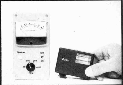
MODERN 35 MM SLR CAMERAS INCLUDE SO MUCH ELECTRONIC hardware that it's almost impossible to take a poor picture providing you're taking pictures in the sunlight, available light, or "available darkness". But, as soon as artificial illumination from a flash is needed it's a "whole 'nother ballgame." The reason is that you often must depend on film guide numbers for proper exposure, and they have no relation to the real world where the color of the walls, height of the ceiling, and depth behind the subject often make those guide numbers relatively meaningless. Even modern automatic strobes with a built-in light sensor can be fooled by the colors of the room, height of the ceiling, etc.
Then, there are extreme close ups, or macro-photography.
Even auto-strobes with normally accurate light sensors are often fooled when the light-to-subject distance is small. The result is overexposed, washed-out detail.
But use Flash-meter that is specifically designed for electronic flash and most difficult lighting situations are easily resolved with the proper film exposure.
Flash-meter is used in the same way as a standard incident-light meter: You place it at the subject location facing between the camera and the flash-or at the camera if the flash is mounted on the camera bracket, fire the flash, and then read the required f-stop (lens opening) directly off the meter's scale. (There is no interpolation of scale reading to exposure chart required.) Depending on the quality of components used for the project, the Flashmeter reading will hold (hang-up) from one to several minutes before drift to zero causes any significant error in the reading.
The Flash-meter features meter-scale calibration in full stops from f:4.0 to f:22 for film speeds from E1 25 to E1 400, instant meter reset, and a built-in battery check. By the way, E1 means Exposure Index, and in most cases is identical to the ASA rating found on all film packages. Some time ago, that was not the case. Also, some photographers use their own E1 to match their equipment and studio requirements.
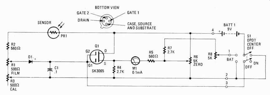
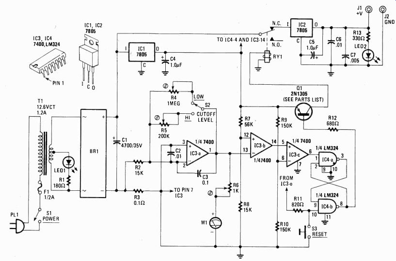
--- FIG. 1. SCHEMATIC DIAGRAM FOR FLASHMETER uses a high-impedance
input FET to amplify charges on capacitor C1. The capacitor's charge
is made possible by the dropping in value of PR1 when in the presence of
a bright light flash. Diode D1 allows C1 to charge through it. C1 cannot
discharge, because both the diode and the gates on the FET present resistances
that limits current leakage to a few microamperes. C1 will hold a charge
long enough to take a reading before It begins to drift downward.
How it works
Resistors R1, R2, and R3 together with photo-resistor PR 1 form a voltage divider across the 9-volt power source (see Fig. 1). Part of the voltage is tapped off at FILM SPEED potentiometer R1 and fed to capacitor C1. Diode D1 serves primarily as a "one-way gate" so that the resistor network doesn't discharge C1. Normally, PR1's resistance is extremely high compared to the rest of the divider, so that virtually no voltage is developed at R1's tap. What voltage there is, is less than diode D1's "breakover" rating so that no charge is applied to C1. When the flash is set off, its light is summed with the room's ambient light causing PR1's resistance to decrease sharply. That makes the voltage at R1's wiper rise. When the voltage rises, it exceeds D1 's "breakover" point and' the diode conducts. Current flows through D1, charging capacitor C1.
Transistor Q1 is an insulated gate FET, whose input impedance is in the thousands of Megohms. It senses the voltage across C1, which is dependent on the intensity of the light from the flash that reaches sensor PR1, and results in a reading on meter MI (see Fig. 1). Because of Q1's unusually high impedance, it causes no appreciable discharge of C1 , so meter M1 's indication is sustained over a relatively long time period.
Photoresistor PR1 is a special high-speed type, whose color sensitivity and resistance range was specifically selected for this project. The Flash-meter will probably not work with any other photoresistor.
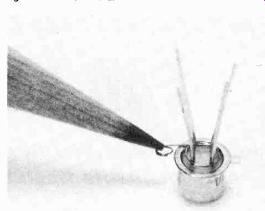
--- THE FIELD-EFFECT TRANSISTOR (FET) IS VERY SENSITIVE to electrostatic
charge before it is installed onto the printed-circuit board. Pencil points
to metal wire spring that shorts the four FET leads together. Do not remove
spring from FET until after the leads have been soldered in place on the
printed-circuit board and the battery is connected.
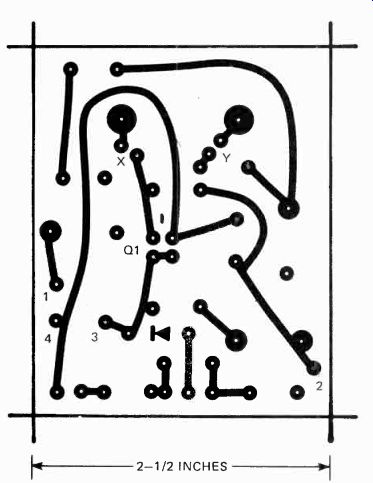
FIG. 2. PRINTED- CIRCUIT TEMPLATE FOR FLASHMETER is simple to copy. If
you prefer to lay out your own-do so, since the circuit is not critical
to parts placement.
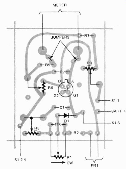
FIG. 3. PARTS-LAYOUT DIAGRAM is shown with printed-circuit board, foil-surface
down. Large terminal circles near top of board are for meter M1 terminal
holes. Refer to text for further information. Note position of FET's case
tab. Your hookup should match this layout.
PARTS LIST
RESISTORS
All 1/4-watt, 10% or better unless otherwise specified
R1-500-ohm potentiometer, linear taper, preferably wire-wound
R2, R5-560 ohms
R3-500-ohm trimmer potentiometer, flat mounting
R4, R7-2700 ohms
R6, R8-5000-ohm trimmer potentiometer, flat mounting
PR1-Photoresistor, Clairex 903.
CAPACITOR
C1-0.1 µF Mylar or disc capacitor, rated higher than 10 volt
SEMICONDUCTORS
D1-1N456A
Q1-MOSFET, RCA SK3065
MISCELLANEOUS
BATT1-- Battery, 9-volt, type 2U6 or equivalent
M1-Meter, 0-1 mA DC, Calectro D1-912
S1-Switch, DPDT center-off-preferably one side spring return
Cabinet, white dome, PC materials, knob, white translucent jewel or dome, etc.
Construction
Warning! Do not handle Q1 until told to do so! If you are unfamiliar with handling FET's, you may blow Q1 before you are ready to install it.
The Flashmeter is built into a plastic cabinet that measures approximately 3 1/2 x 2 x 5 1/8 inches. I used a Hammond cabinet for Flashmeter shown in the photos. Hammond cabinets tend to shatter easily when mounting holes are drilled. If you aren't particularly adept at cutting holes in a "hard" plastic cabinet, substitute a "soft' plastic cabinet such as those sold by Radio Shack. They aren't as classy-looking as the Hammond's, but softer plastic is easier to work with if you don't have a drill press or a variable-speed electric drill.
All component values are critical and few substitutions may be made. (If you can't obtain the specified components or their recommended substitutions don't build the project--it won't work properly.) Potentiometer R1, the FILM SPEED control, is particularly critical. It must be 500 ohms and it must have a linear taper.
The unit shown in the photographs is a wirewound pot often found in "surplus" stores for $1 to $3. A wirewound is suggested because it's more stable and more likely to hold its setting even if handled roughly. But don't spend a fortune on the pot. If you can't get a wirewound at a decent price use a standard carbon type. If you can't obtain a 500-ohm unit, then check out a local TV parts supplier, and see if you can get two 1000-ohm pots on the same control shaft (dual pots). That may be easier to find. Then, tie all three common terminals in parallel (upper end to upper end, wiper to wiper, and lower end to lower end). You now have a 500-ohm pot with no tracking error. In fact, the resulting network of two pots may be more linear than one pot alone.
In the event you absolutely cannot obtain a 500-ohm pot, you can use a larger size if a fixed resistor is connected in parallel with R1 across the end terminals, and the combined resistance of the pot and the resistor sums in parallel to 500 ohms. The resulting tolerance of the network is ± 10% of the expected linear tracking. There are two extra holes on the PC board for that resistor. However, bear in mind that the Film Speed calibration won't be reasonably linear, and might be all scrunched at one end if R1 isn't 500 ohms. The parallel resistance arrangement has been provided only for those builders who in no way can get a 500-ohm pot.
Most of the circuit for the Flashmeter is assembled on a printed-circuit board (See Figs. 2 and 3) that mounts directly on the back of the meter, and the connections from the PC foils to the meter terminals are automatic when the board is secured to the meter.
The meter used must be a Calectro type D1-912 0-1 mA DC with screw-type terminals. The same meter, or a similar model was sold under different labels-among them Radio Shack. But some of the other brands changed the connections, substituting solder terminals for the screw connections. The printed-circuit board won't mate with the solder-type terminals. Also, double-check the Calectro model and make certain that it has screw terminals. At the time this article was prepared, Calectro used screw terminals, but in this day and age anything can change overnight. Don't assume that the meter is the same simply because the catalog number is the same.
Some similar meters had reversed meter-terminal polarity.
The PC template allows for that. If you look at the printed-circuit template (Fig. 2) you'll note the two large foil pads that are the meter terminal connections. The foils to each pad are broken at X and Y. Looking at the back of the meter when held upright, if the right hand meter terminal is marked with a + , connect a jumper between the two X holes and a jumper between the two Y holes. If your meter's left hand terminal is marked with a + , connect insulated jumper wires from the top X hole to the lower Y hole, and from the upper Y hole to the lower X hole. What you must end up with is the meter's "+" terminal connected directly to Q1 's "s" terminal.
Make the PC board using the template in Fig. 2 and put the numbered markings on your board exactly as shown on the template. Final assembly will be confusing without the numbers because they match connections shown in the schematic diagram. Note that the template has a small dash representing Q1's tab, and also a symbol to indicate diode D1's polarity.
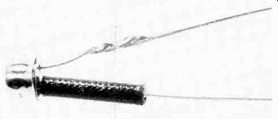
---------- PHOTOTRANSISTOR R1 LEADS MUST BE EXTENDED prior to installation
on the printed-circuit board. Slip a sleeve insulator over one of the
leads to avoid their accidental shorting. Use bare, solid hookup wire and
a drop of solder.
--------------
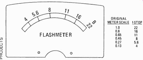
FIG. 4. AUTHOR'S FLASHMETER METER SCALE LAYOUT is provided here to assist
you in either making your own scale or copying the above. A carefully drawn
and Inked scale art will make your unit very handsome and give it the pro
look.
LIGHT INTEGRATOR is a translucent white lampholder which will house photoresistor PR1. Prior to soldering the leads of PR1 be sure that the top of PR1 is 1/4 inch from inside top of lampholder. That should place the photoresistor about flush with the surface of the printed-circuit board. Note that light integrator is cemented in place.
Working with a FET
Carefully unpack Q1 and look at the base of the leads where they enter the transistor. You will find a shorting wire wrapped around the leads. DON’T REMOVE THIS SHORTING WIRE UNTIL THE ENTIRE PROJECT IS COMPLETED. Q1 is a MOSFET, and is very susceptible to static electricity prior to installation without the shorting wire across the leads. One static "shot" and Q1 is "blown." The shorting wire is removed after the unit is wired and the battery has been installed.
Mount all components, including the connecting wires on the PC board (see Fig. 3), but don't install the meter. Either use color-coded wires to match the numbered connection holes, or tag each wire with an adhesive label.
Set the board aside for the moment and mount all front-panel parts. Switch S1 is a DPDT, center-off toggle device; preferably spring-return from one side. Use the spring-return side for the BAT (battery test) position. Mount potentiometer R1 1 1/4 inches from the bottom of the cabinet. Mount resistive sensor PC1 and switch S1 on a line 2 inches from the bottom (check the photos). Resistive sensor PR1 must look into a white "light integrator". The integrator in the unit shown uses the white lamp-holder from a set of five colored holders supplied with a blister-packaged Muralite low-voltage panel lamp kit. You can substitute the dome or cover from a white pilot-lamp assembly. In fact, any translucent white dome can be used.
When all panel components, including the meter, have been installed, mount the PC board on the meter terminals, connect the wires from the board to the switch and pot, and then install sensor PC1. To install PC1, first solder a 1-inch solid wire to each of PC's leads and place a'-inch length of insulation over one lead. Slip PC1 into the white integrator dome, slide its wires into the PC-board holes, and then position PC1 before soldering, so that it is at least 1/4 inch back from the front of the integrator. PC1 must look "into" the integrator; if it's flush with the front of the integrator it won't read light coming from the sides correctly.
The meter scale
You can either recalibrate the supplied meter scale, or make an entirely new scale using the full-scale template (see Fig. 4). If you want simply to recalibrate the existing scale, use the conversion values in the chart, which shows the f-stop value for the original scale calibrations. If you decide to make an entirely new scale, do it this way: First, create the new scale on white paper. You can do that either by making a Xerox copy of the template, or by using the template itself.
To install the new scale, use a small screwdriver slipped under the top of the meter cover to gently pop the cover off the meter. Taking extra care not to damage the pointer, remove the two Phillips screws that hold the scale and slide it out from under the point. Slide, don't lift. Lifting will damage the pointer. Flip the scale over so the metal side is up. Cut out the new scale (or Xerox copy), punch out the screw holes from the new paper scale, and apply a very thin layer of rubber cement to the back. Then position the new scale on the metal scale, smooth out the bubbles, and allow the cement to dry. Slide the new scale under the meter pointer, insert the screws (don't let them fall into the meter), and install the cover.
Powering up Make certain S1 is in the center OFF position, install the battery, and carefully pull the shorting wire off Q1. Make sure none of Q1's leads are touching.
Set R1 fully counterclockwise and install a knob with the pointer at 7 o'clock. If the control is rotated fully clockwise, the pointer should be at 5 o'clock. Fudge the knob's adjustment until its pointer falls equally on either side of the 6 o'clock position when the knob is rotated to both extreme settings.
Set S1 to BAT and adjust trimmer pot R8 until the meter pointer falls directly on the scale calibration marked B(attery); which is also the f:22 mark. Then flip S1 down to ON and adjust trimmer pot R6 so that the meter pointer falls directly over the extreme left calibration, which is really the original "0" calibration. Set S 1 to the center or OFF position. Then adjust trimmer R3 to approximately mid-position.
Set FILM SPEED control R1 so the pointer is at 3 o'clock and mark the panel opposite the pointer 400-meaning a film (speed) E1 rating of 400. With the cover off, set up the meter on a table, then set S1 first to BAT (which discharges C1) and immediately to ON. Position an electronic flash in front of the meter at such a distance that the normal exposure for E1 400 film would be f:22. Use the flash's exposure dial or recommended guide number calculation to determine the correct distance for f:22. Fire the flash and note the meter reading. It will probably be less than f.22 or off -scale to the right. Let the flash recharge, adjust R3 about Vs of full rotation and fire the flash again. Note the new meter reading. Repeat the flash and adjustment of R3 until the meter indicates f:22. R3 is calibrated when the meter indicates f:22.
Next, calibrate R1 for E1 200 by setting R1 to approximately 1 o'clock, momentarily set S1 to BAT and then back to ON, and fire the flash. The meter should indicate f:16.
Fudge R1's adjustment until you get the f:16 reading and mark the panel opposite the knob pointer 200. Then set R1 to approximately 11 o'clock, set S 1 to BAT and then ON, fire the flash, and fudge R1's adjustment for an f:11 reading. Set R1 to 9 o'clock, set S1 from BAT to ON, fire the flash, and fudge R1 for an f:5.6 reading. You should now have a good idea how to calibrate the meter for nay film speed. The only things you must be certain of is that the flash is set for the correct distance fort 22 with a 400 speed film, that you have let the flash fully recharge before each test flash, and that you have discharged the meter reading by setting S1 first to BAT and then to ON. (The BAT position discharges capacitor C1 and "zeroes" the meter.)
Reading drifts?
When you start the calibration tests, if you find that the meter reading starts to decrease almost instantly, rather than "holding" for a relatively long period, either capacitor C1 is "leaky" or diode D1 is contaminated. If you have used a Mylar or disc capacitor for C1 it's probably OK, so try the diode first: Wipe it down with alcohol and keep your fingers off after the wipe; skin oil is a great conductor. If you still get a fast decay of the reading, try a different diode. Normally, the specified diode works quite well. If you have substituted anything else, the normal leakage might be too great for this circuit.
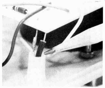
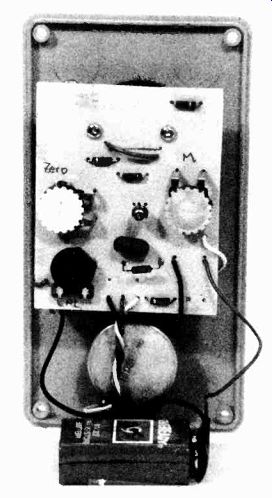
--- REAR VIEW OF THE FRONT PANEL shows printed -circuit board mounted
on meter terminals-see two screwheads near top of board. Use a strip
of double -sided tape to secure 9-volt battery to potentiometer case
shown in lower part of photo.
Using the Flashmeter
To use the meter, simply set it at the subject's location (what the camera will shoot) with the sensor facing midway between the electronic flash and the camera (or directly at the camera if the flash it mounted on the camera), set R1 to the FILM SPEED, set S1 first to BAT and then to ON, and fire the flash. The meter reading is the proper f-stop for lighting the subject itself. If you're bouncing the flash, point the sensor at the camera and then fire the flash into the bouncing surface.
Keep in mind that bounce flash can loose so much light that the meter will barely budge off its pin. SP.