by ALAN S. COBB
Why use smoke signals to spot troubles? Disconnect the regulated power supply before its circuit elements go poof!
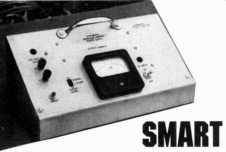
HAVE YOU EVER MADE THE CONNECTIONS ON A BREADBOARD project and noticed smoke rising from your power supply or other components, as a short circuit fries them? Then get smart-not you, but your power supply! This "smart" power supply was designed after the author blew too many fuses and rectifiers because of accidental shorts during TTL prototyping.
The Smart Power Supply is like a circuit breaker, except that it is much faster and can be very accurately pre-set to shut down at an exact level of load current. Conventional circuit breakers aren't as precise. Other units may take from 5 to 30 seconds to open when the load current exceeds 200% of its rating. A lot of damage can take place in those smoking seconds. Although the 7805 regulator chip used on most 5-volt supplies has internal circuits to shut itself down when excessive current causes overheating, if you're using enough heatsink the process is a gradual one, taking much longer than the Smart Power Supply.
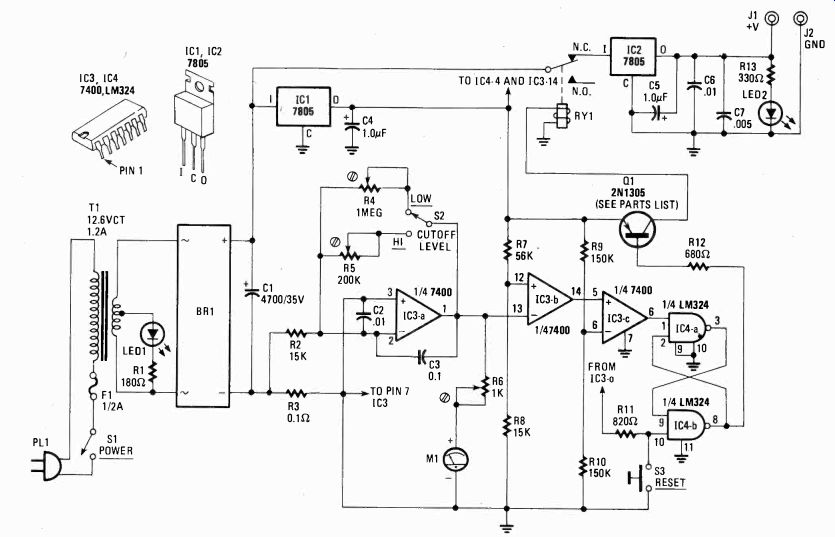
---- SCHEMATIC DIAGRAM FOR THE SMART POWER SUPPLY is as simple
as its name. After the coarse DC voltage is rectified by diode bridge BR1,
two separate regulated 5-VDC supplies thrive off it. One 5-VDC supply, developed
by IC1, powers the current-sensing circuit and cut-out relay RY1. The remaining
5-VDC supply is switched on and off by the action of the relay and RESET
switch S3.
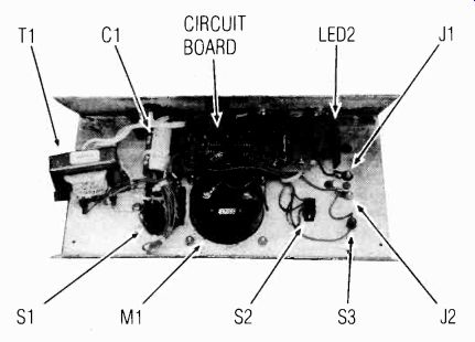
------ PARTS LOCATION LAYOUT FOR THE SMART POWER SUPPLY. Nothing
is critical here, so let neatness and cost determine best practical way
to proceed with project.
Construction
Most of the parts involved can be purchased at neighborhood or mail order outlets. To simplify the design and reduce the cost, you could leave out the 250 mA low range by only using the high range's 200,000-ohm feedback trimpot, R5 (see Fig. 1). You could leave out the meter, too, although it is helpful to see how changes in your breadboard experiments affect the current drawn from the supply.
Although other chassis can be used, one with a sloping front-panel makes the meter and indicator LED's easier to read. The author fabricated his own from sheet 18-gauge aluminum. After laying out the pattern on the metal, cut it out with a saber saw. The required bends were made by using pieces of/winch aluminum, plate and "C" clamps to hold the sheet metal to the bench while the folds were formed with hand pressure and a lot of hammering. After bending and drilling the chassis, immerse it in a solution of 1/2-can of Drano (lye) to 3 gallons of water for several hours to give the aluminum a satin finish. It is important to submerge the aluminum completely in the solution. If part remains exposed, a crusty streak will form where the metal first meets the liquid. After the etching, follow with a complete rinse and scrub down the metal to remove all lye. Next apply press-on transfer letters and spray on several coats of clear polyurethane finish over several days to protect the lettering.
Instead of rubber feet for the enclosure use two 6-inch long strips of 0.5 inch self-sticking weather strip on the bottom.
The final step in chassis preparation is to add a handle on top to make the supply easier to carry.
Most of the electronic components are mounted on a standard 6 x 2-inch circuit board with the same pattern as a conventional 6 x 2-inch solderless breadboard. The circuit board was mounted on the top chassis section (see photo) with 1-inch 4-40 machine screws and 3/4-inch spacers. The foil side of the card is exposed so that the wires to the off-board components can be easily soldered in place after everything else is installed. Most of the on-board components can be mounted on the underside (non-foil side) of this card, while C1 and the three trimpots (R4, R5, and R6) are put on the foil side for easy access and adjustment.
The two 7805 regulators (IC1 and IC2) are bolted to the back of the chassis close to the board. Thus the entire enclosure acts as a heat sink. Be sure to mount C4 and C5 right on top of the 7805's with short leads.
How the circuit works
The basic circuit is the same as a regular fused, 1.0-amp power supply. (See Fig. 1.) The "intelligence" circuitry consists of two ICs, a 7400 (IC3), and a LM324 (IC4). The LM324 is a quad Op-Amp package that can be powered by a single 5-volt supply rather than the normal dual supplies. As with the other control logic, it draws power through its own 7805 regulator (IC1), so the relay doesn't have to be put between the load and primary regulator (IC2) causing a voltage drop.
Both inputs (pins 9 and 10) on IC4 unused Op-Amp should be grounded to reduce noise, but do not ground the output (pin 8). To save a little current, ground the inputs (pins 4, 5, 12, and 13) on IC3 unused gates and leave their outputs unconnected.
---------------
PARTS LIST
RESISTORS ,
All resistors 1/2 watt, 10% unless otherwise noted
R1-180 ohms
R2, R8-15,000 ohms
R3 0.1 ohm
R4-1 megohm printed circuit potentiometer (Radio Shack 271-229)
R5-200,000 ohm printed circuit potentiometer
R6-1,000 ohms printed circuit potentiometer
R7-56,000 ohms
R9, R10-150,000
R11-820 ohms
R12-680 ohms
R13-330 ohms
Calibration/testing resistors: 10-ohm, 12-watt adjustable tap 50-ohm, 12-watt adjustable tap
CAPACITORS
C1--4,700 µF 35 volts, electrolytic
C2, C6--0.1 µF ceramic disc
C3--10.1 µF ceramic disc
C4, C5--1.0 µF
Tantalum
C7-.005 µF ceramic disc
SEMICONDUCTORS
IC1, IC2-7805 voltage regulator
IC3-7400 quad nand gate
IC4-LM324 quad op amp
Q1-PNP transistor 2N1305, HEP 253 or equivalent
LED1, LED2-jumbo
LED BR1-full wave bridge rectifier, 50 PIV, 1.4 A. or better
MISCELLANEOUS
T1-transformer, 12.6 volt 1.2 amp secondary (Radio Shack 273-1505)
J1, J2-insulated binding post
S1-SPST toggle
S2-SPDT slide switch
S3-momentary contact pushbutton switch, normally open
RY1-5 VDC subminiature DIP relay (Radio Shack 275-216)
F1-fuse, 0.5 A with holder
M1-0.0-1.0 mA DC meter
Aluminum sheet metal, wirer, spacers, handle, hardware, etc.
---------------
The DC-load current passes through resistor R3. The voltage drop across R3 is amplified by the first Op-Amp, IC3-a.
That amplified voltage is fed to the comparator IC3-b. When the amplified voltage goes above the comparator's reference voltage, its output (pin 14) snaps low. The second comparator (IC3-c) makes that snap action even more crisp. When its non-inverting input (pin 5) goes lower than the reference (pin 6), its output goes low (pin 7). That output of the second comparator is fed to the latch (gates IC4-a and IC4-b). When pin 1 of IC3-a goes low, the output of gate IC4-b (pin 8) will go low; that causes transistor Q1 to conduct and open the relay cutting off the load current. The latch will hold pin 8 low even after pin 1 of IC3-a goes high again. If there were no latch circuit here, the system would cycle continuously, first opening and then closing again as soon as it disconnected its load. Switch S3 is used to reset the latch and close the relay once the overload has been cured. It does that by driving pin 10 temporarily high.
Switch S2 provides two sensitivity ranges for tile supply.
The low range uses a 200,000-ohm trimmer pot, RS, and will open for load currents greater than about 250 milliamps. The high range uses the 1 Megohm trimmer potentiometer as a feedback leg and can be adjusted to shut the supply down for load currents in the 1.0 A range. The lower, more sensitive, range can be used when working on simple circuits of only a few chips that don't draw more than 250 mA. The meter, of course, will give a more accurate reading of small currents than at the 1.0 A setting.
--------------------
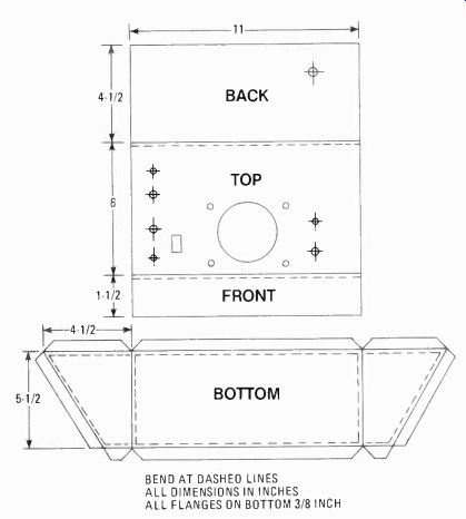
FIG. 2. MAKE YOUR OWN SLOPING-PANEL CABINET. It's easy, and you custom
it to your needs. Of course you can resort to any cabinet style commercially
available, but you pay the price. Hole location and sizes depend on the
parts used.
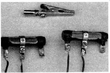
----- HERE ARE ALL THE PARTS YOU NEED to calibrate the Smart Power
Supply. Wire leads are permanently soldered to the resistors to assure
good contact during tests. The clip suggests possible lead termination for
rapid connection during test.
-------------------
Testing and adjustment
To adjust the trip point of the circuit, use a 10-ohm, 12-watt variable resistor for the 1.0-amp range and a 50-ohm, 12-watt resistor for the 250-mA range. In the high range, the supply is loaded with the 10-ohm resistor adjusted to 5 ohms (or a fixed 5-ohm power resistor). The circuit will then be putting out 1.0 amp. (5 V/5 ohms = 1 A) Adjust trimpot R5 and meter pot R6 so that the meter is reading full scale (1 mA = 1.0 A) and the relay has just tripped. Retest by slowly decreasing the load resistance to 5 ohms. When the load is equal to 5 ohms, the meter should just be hitting full scale and the shutoff relay should trip, causing the ammeter to drop down scale again. A similar process is used to calibrate the 250-mA low range. Note: you won't be able to get the meter to read exactly zero for a zero-load current, since there will still be a minimum current flowing through 1C1 and the control circuitry.
Examine Fig. 1 carefully and you'll notice that the unused terminal of RY1 will get 5-volts DC when there is an overload. That action suggests a possible alarm system to alert the project builder. You could connect a flashing LED to this circuit, or any other alarm system that comes to mind. Also, the circuit is simple enough to allow many other variations that will permit customizing the project for your needs.