Couple a 1-transistor oscillator with a pocket transistor radio for a sensitive metal detector you can build this evening.
By HERB FRIEDMAN
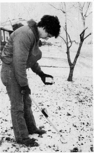
IT WON'T FIND THE LOST TREASURE OF BLACKBEARD, the Pirate, or a new mother lode of gold and silver, but the Junk-Box Metal Detector will locate the main water or gas shut-off valve that's buried under a few inches of snow or grass. It will also locate a tuna-salad-on-white sandwich wrapped in tinfoil that was lost at the beach during last summer's company picnic; and it will keep the junior members of the family busy for hours seeking "Grandpa's Lost Treasure"--a few larger coins buried just under the sand or soil.
It will even locate electrical boxes that someone buried inside a wall; it might detect concealed water pipes and electrical BX cables and conduits if they're near the outer surface of a plaster or drywall; and it will find metallic drain lines concealed behind plaster before you drill into them.
Best of all, you can whip this metal detector together in just a few hours because the critical part--the "detector"--is an ordinary transistor pocket radio.
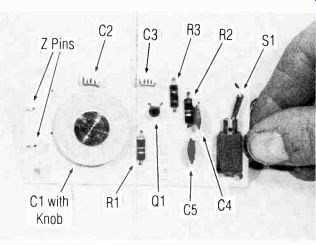
------------ THE MAIN TRANSMITTER (METAL DETECTOR) is assembled on a small printed-circuit board that also series as the cover for its cabinet.
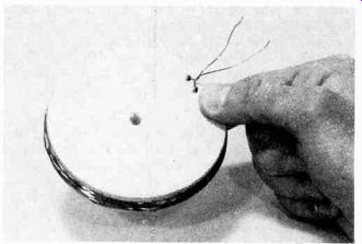
------------- THE SEARCH COIL IS WOUND ON A 4-TO 6-INCH WOOD FORM made from 3/4-in. thick lumber. Two holes drilled at an angle from the top to the side keep the turns of wire from unwinding until you can cement them in place. A twist or two is all it takes to secure the ends.
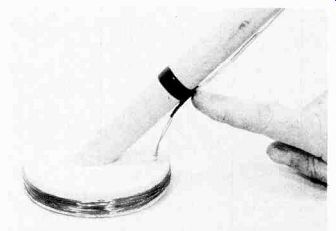
----------- A BROOMSTICK MAKES A GOOD HANDLE. Cut the end at a 45 angle (or whatever is convenient) and attach the search coil with a single wood or sheet-metal screw. Everything must be rigid, so secure L1's leads to the handle with a few turns of plastic tape.
How it works
Metal is detected by the sensing transmitter (called the metal detector) shown in the photographs and schematic diagram; it is indicated by a heterodyne beat in a pocket transistor radio. The Junk Box Metal Detector unit is a broadcast-band oscillator with an RF output between approximately 1000 and 1600 kHz whose tuning coil, L1, is mounted on the end of a handle. Tuning coil L1's inductive effect is varied when the coil passes over, or is brought in the vicinity of, a metal object. That variation in inductance changes the oscillator's frequency. The exact why of L1's inductance change can be either to ferrous metals or capacitive loading by other metals nearby.
A weak to moderately strong station received by the transistor radio serves as the indicator for the metal detector. First, with the metal detector turned on while the search coil its held up in the air outdoors, away from all metal, the metal detector's frequency is adjusted by tuning capacitor C1 so it is approximately that of the station received by the radio. As C 1 is adjusted, the user hears the beat whistle or heterodyne as the oscillator frequency "beats" against the station.
C1 is adjusted so that the beat is an annoying high-pitched squeal of approximately 1000-3000 Hz.
The coil is swept over the ground or wall with as little clearance as is possible. The coil can even touch the surface. When the coil passes over metal the oscillator frequency changes because the inductive effect of the search coil changes. The larger the metal surface under the coil, the greater the change in inductance, the greater the change in oscillator frequency, and hence, the greater the change in the beat frequency.
Because this is a rather simple circuit, proximity effects are not cancelled. There might be a slight change in the beat frequency when the coil is first positioned near the ground or wall. But that is a constant once the coil is near the surface and will not change noticeably when the search coil is moved unless the coil passes over metal, in which case the user hears the beat frequency change as the coil is swept back and forth slowly. Practice will train the ear to ignore false responses.
Construction
Oscillator coil L1 is wound on a wood disk approximately 4 to 6 inches in diameter. The disk-diameter dimension isn't critical as long as it's within the range given. Wooden 4-inch disks are often sold in model shops for use as wheels, so the 4-inch size was used for the prototype unit shown in the photos. Pine stocks 3/4-inch thick is about the easiest to handle; anything narrower will make the coil difficult to wind.
The coil itself is 18 turns of #22 solid insulated magnet or copper wire "scramble-wound" on the wood form. Scramble-wound means you don't have to be neat, the windings can criss-cross. Magnet and copper wire insulation is varnish or poly-thermaleze. Cotton or plastic insulated wire can be used, but they're bulky and difficult to wind. You can substitute wire in the range of #20 to #30. Wire size #22 is suggested because it is commonly available at Radio Shack and other electronic parts distributors.
First step in winding L1 is to prepare the wood form.
Drill a starting screw hole through its center which for the wood brass screw that secures the coil to the handle. Then drill two holes spaced about 1/2-inch apart diagonally from the top of the form to the edge.
The wire(s) will pass through those holes and provide a secure coil. The coil turns must be secure. If any windings flop or move when the coil is swept it will cause false indications in the radio.
Tensilize about 20 feet of wire. The wire must be tensilized so it doesn't spring loose when you release winding tension on the coil. To tensilize the wire, clamp one end of the wire in a vise and pull on the other end gently until you feel a slight give--the wire will go dead slack. Remember: Ease off as soon as you feel the give; too much pull will cause the wire to break.
Pass one end of the wire through a hole from the side of the wood disk, allowing about 3 inches of wire to stick out through the top of the wood-coil form. Wind 18 turns as tight as is possible, then push the winding so you can get at the other hole, and pass the free end of the wire through the hole. Pull both wires tight and twist them together two or three times so the winding can't spring back. Saturate the coil with airplane cement, Duco, or a similar glue to prevent it from getting loose.
The remainder of the circuit (see Fig. 1) is assembled on a printed-circuit board (see Figs. 2 and 3) that serves as a cover for a plastic case approximately 2 1/2 x 1 1/4 x 4 inches. A full-scale foil templet is provided in Fig. 2.
The layout isn't critical as long as it approximates the foil pattern shown. The foil "square" serves as a shield for tuning-capacitor C1 and should not be eliminated.
You can substitute a general replacement transistor for the specified transistor, Q1 (see Fig. 1). To avoid excessive frequency shifts caused by heat from the sun, C2 and C3 should be some form of mica, silver mica, or tubular ceramic; but if all you have are some ordinary ceramic discs go ahead and use them-they will probably work reasonably well. (The author's unit uses tubular ceramics from a "100-capacitors-for-$2 kit".)
------------------
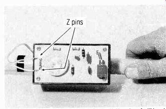
--- NO! THE LETTERING ISN'T UPSIDE DOWN. Your hand will be at the top, so the entire transmitter is mounted the "wrong way" on the handle. The wires from L1 are wrapped around the Z pins and then soldered.
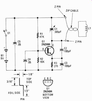
FIG. 1--JUNKBOX METAL DETECTOR SCHEMATIC DIAGRAM shows a simple RF oscillator. Loading on coil L1 determines the amount of detuning, or drifting of frequency. from preset frequency by C1.
----------
PARTS LIST
RESISTORS
1/4 watt or 1/2 watt, 10%
R1-47,000 ohms
R2-10,000 ohms
R3-270 ohms
CAPA CITORS
C1-365-pF miniature polyvaricon capacitor with dial knob
C2, C3-100-pF tubular ceramic or mica, see text
C4, C5-0.05-µF ceramic disc or Mylar
SEMICONDUCTOR
Q1-NPN transistor, 2N2484 or equiv.
MISCELLANEOUS
L1-Homebrew search coil, see text
S1-SPST printed circuit switch, see text B1-9 volt battery, type 2U6 or equiv.
Misc.--Cabinet, #22 enamel wire, battery holder, handle, hook-up wire, solder, etc.
Note. The 365-pF polyvaricon tuning capacitor, (C1) with dial knob is available for $6 postpaid (postage and handling included) from Custom Components, Box 153, Malverne, NY 11565. NY State residents must add sales tax. $1 additional to Canada.
---------
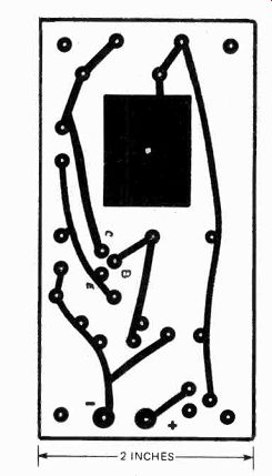
FIG. 2--USE THE AUTHOR'S PC TEMPLATE for best results.
Make exact same-size copy including the large square area that serves as a shield for capacitor C1.
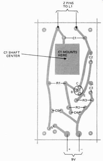
FIG. 3--PARTS LAYOUT FOR THE PRINTED-CIRCUIT BOARD. You may have to modify
the board a bit to compensate for different battery switch Si if you
do not use author's manufactured type. Leads connected to C1's terminals
connect to terminals on PC board. See text for details.
Printed-circuit switches don't usually come cheap.
However, a flat mount with PC terminals, was purchased for something like $1 from Chaney Electronics.
(It's convenient to install and a great buy! Stock up if you can.) If you substitute a different switch, change the printed-circuit template's connections accordingly.
Tuning-capacitor C1 is a 365-pF miniature polyvaricon with a 1 1/4 inch tuning dial that also serves as a knob. You can substitute any type of 365-pF "poly" capacitor because all common poly capacitor terminals will fit the PC foil layout. Make C1's connections carefully. C1's lugs are usually "brite-finish" and don't take, solder easily; but you cannot use excessive soldering heat or you'll damage the capacitor. Follow this procedure to install C1: Wrap a single turn of solid hook-up wire around each of C1's lugs and squeeze them tight with long nose pliers. Dip the end of your solder in non-corrosive (non acid) soldering paste and then solder a wire to the lug. Then do it again for the other solder joint. It will take little soldering heat if you use the paste. But remember, just a dab will do.
Coil L1's connections to the printed-circuit board are made through "Z" pins fashioned from #20 solid wire, or you can use a wire wrap terminal (such as sold by Chaney Electronics). The connections must be formed into a "Z" so they don't fall through the board when the wires from L1 are soldered. The dimensions for the "Z" pins are shown in Fig. 1. They aren't critical; any shape that keeps them from falling through the board will be OK. While L1 can be soldered directly to the board, the "Z" terminals will allow you to easily remove L1 without damage to the foils if the checkout shows L 1 wasn't properly wound and you have to disconnect it from the PC board.
Battery B1, a 9-volt type such as used for transistor radios, is held inside the plastic cabinet by a small transistor battery clamp sold by Radio Shack (among others). The handle is about 3-feet long...use whatever length is convenient for you. Either cut down an old broom handle or buy a 1 or 1 1/2-inch diameter wood dowel. Cut the bottom end at a 45-degree angle.
Secure the plastic cabinet to the handle about 1/3 down from the top. Then secure coil L1 to the bottom with a single screw passing through the center of the form.
Scrape the insulation from the free ends of L1, tin with solder, and attach a length of plastic insulated zip wire such as you would use to connect speakers to an amplifier. (The extra-thin stuff, #22 or #24, is suggested.) Insulate the connections with shrink tubing or spaghetti and secure the zip wire to the handle with a turn or two or plastic tape. Run the wire up the handle and connect to the two "Z" terminals on the PC board.
Test before using Tune a pocket radio to a station at about 1000 kHz.
Turn on the metal detector and slowly adjust C1. At some point you should hear the heterodyne whistle in the radio. If you don't hear the whistle, tune to a station higher in frequency, say 1100 kHz, and try again. If you cannot hear a whistle all the way up to 1600 kHz check for wiring error. If you can get the heterodyne beats only on stations near the top of the dial, above 1300 kHz, most likely there is something wrong with L1; it probably needs a few turns of wire, or the form is less than 4 inches in diameter. But if you can receive a top-of-the-band station clearly, and you get a clean heterodyne, you can still use the detector.
Using the metal detector If you place the radio too close to the metal detector if will be jammed by the metal detector, so don't secure it to the handle. The shirt pocket is a good location. On the other hand, if the received signal is too strong it will jam out the signal from the metal detector.
Try to use a station of weak-to-moderate signal strength. Turn on the metal detector, hold the coil in the air, and adjust C1 for a high pitched, raucous squeal from the radio. Then sweep the search coil.
If C1 is set so that the heterodyne beat is a low frequency, you will hardly notice minute changes in tone quality produced by small quantities of metal under the search coil. Shoot for an adjustment of C1 that provides a tone in the range of 1000 to 3000 Hz-frequencies to which the ear is most sensitive.
You must remember that the Metal Detector oscillator circuit produces signals on the broadcast band. Do not let the unit run when not necessary for fear of interfering with another's listening pleasure.