By H. B. CONANT *
* Conant Laboratories, Lincoln, Neb.
THE best test for any product is one which evaluates its ability to do the job for which it was intended. Therefore any good test method must simulate some typical operating condition of the product under test. In its most common function as a power supply filter, the electrolytic capacitor receives current pulses from a rectifier. It stores these for delivery to the do load circuits during the intervals between rectifier pulses. The rectified ac is thus smoothed to a continuous direct current-if the capacitance is large enough, or if several filter sections are used.
If there is too little capacitance, some of the rectifier pulses remain superimposed upon the do output of the filter and produce what is known as "ripple." (Ripple is proportional to current drawn by the dc load and inversely proportional to the capacitance of the filter capacitors.)
The test circuit shown places the capacitor under test in typical service where it receives current pulses through the 1N2069 silicon rectifier. Between pulses it partly discharges through the 30,000-ohm load resistor or through about 1,400 ohms when the 1,500-ohm resistor is switched in parallel. With no capacitance connected to the test terminals, ripple voltage is 100% so the meter is set to 100% or full scale with potentiometer R4.
Any capacitance across the test terminals will tend to filter the rectifier output, thereby reducing the ripple voltage and the meter reading.
The 30,000-ohm load resistance provides a range of .03 to 6 uf and with the 1,500-ohm load in parallel, the range is 0.3 to 60 µf. Obviously, an open capacitor will not drop the meter reading; with a shorted capacitor, the meter will read zero. The reading will also be zero if an electrolytic is connected backward. The capacitor can also be damaged. Therefore mark the test terminals prominently to indicate polarity.
Circuit considerations
The meter circuit shown is a full-wave bridge rectifier type ac voltmeter fed through a .04-µf capacitor so that it reads only the ripple voltage. A 100-µa meter was used although any meter up to 1 ma can be used by changing values of capacitance and resistance to suit. The meter rectifier is a Conant catalog No. 1101 selenium bridge, selected both for economy and relative freedom from temperature effects, plus its suitability to this kind of circuit.
Transformer T is principally used for isolation from the line to avoid "fireworks." It is a small power transformer, rated at 117 volt primary and 125 or 150 volts secondary, and is attached with the secondary to the line. Its secondary (original primary) may deliver anything between 75 and 125 volts and should be rated 50 ma or more.
If secondary voltage is greater than 75, the silicon rectifier should be a 1N2070. Control R4 should be of the lowest resistance which in combination with fixed resistor R5 will permit setting the meter to full-scale on either range and on all line voltages likely to be present.
As a suggestion, a 1,000-ohm control may be tried, with 1,000 ohms for the value of R5. If the meter won't come up to full scale, increase the value of R5.
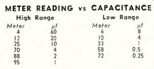
Reduce it if the meter can't be brought down to full scale. [Note that .01 if was used for C and 470 ohms for R5 in making the measurements for the table shown here. Editor]
----------

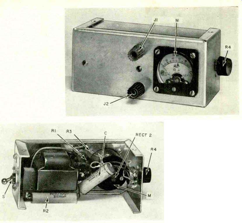
The practical capacitor tester.
Capacitor checker, internal view.
The tester measures ripple voltages. Thus the larger capacitances read lower on the meter scale.


METER READING vs CAPACITANCE
High Range Low Range Meter µf Meter pf 4 60 6 8 12 20 10 4 25 10 33 I 70 4 58 0.5 88 2 72 0.25 95 I
The above readings were made by Mr. Queen of the Radio-Electronics staff.
C was .01 µf and R5 470 ohms in his setup.
R1--30,000 ohms, 5 %, 1/2 watt
R2-1,500 ohms, 10 watts, wirewound
R3--56,000 ohms, 1/2 watt
R4-1,000 ohms, pot (see text)
R5-1,000 ohms, f/2 watt (see text)
C-.04 µf 600 volts paper (see text)
RECT1-1Ñ2069 or equivalent, see text
RECT2-meter rectifier, bridge type (Conant No. 1 101, or equivalent)
5-spdt toggle switch M meter, 0100µa, see text
T transformer, see text (Stancor PA-8241 or similar type)
J1, 2-jacks or binding posts
Case, cord, miscellaneous hardware.
----------------
Calibrating the meter
Calibration will be simplified if the meter scale is calibrated 0-100, representing for calibration purposes 0-100% ripple. As there is a broad capacitance tolerance in commercial electrolytic capacitors, they cannot be used to give precise calibration, but may be close enough for practical use. Exact percentage of ripple depends upon the exact values of the load resistors.
After the tester is built, if possible borrow a pair of precision capacitance standards, say 1 and 10 µf, and find where they read on the two respective ranges. Assuming that each reads 30% ripple on their respective ranges, then 0.5 uf and 5 uf will read 60 %, 4 and 40 µf will read 7 1/e ` /o.
Doubling the capacitance halves the ripple voltage. The response of the ac meter is essentially linear except at the extreme low end of the scale, so calibrations at the very low end will be only approximate.
Quality control
While this tester measures capacitance in terms of ripple voltage, its indications do tell whether a given capacitor is good or bad. For example, let us say an 8-uf capacitor reads 4µf. Obviously it does not reduce the ripple voltage as well as 8µf should, so it should be replaced.
Specifications: Checks all capacitors from approximately .05 to 60 µf.
Can be used for in circuit testing in many circuits.
Performance data: Tested by a RADIO-ELECTRONICS staff member, this capacitance checker was found to work reliably, and to be a simple, accurate and useful instrument.
Subject to small errors introduced by associated circuitry, this tester is practical for in circuit testing. But don't try testing capacitors rated at less than 150 volts. And don't put it into transistor gear unless you want to ruin low-voltage components.
= = =
Also see: