
Design a twin-coupled amplifier for tubes you like to use or build this
35-watt unit using EL34's.
By NORMAN H. CROWHURST
ANY readers asked, "How can we design at win in-coupled amplifier around the output tubes we like using ?" This article answers that question by showing a high-power twin-coupled circuit you can build and how to design one to suit your own tubes, ideas or requirements. . The original twin-coupled-circuit was designed to give high fidelity at low cost.* It used EL84's in its output, and inexpensive output transformers wound in the simplest possible manner to get adequate performance. This, unfortunately, resulted in unequal resistance for the primary halves. While the inequality is not important in the plate screen-coupled transformer, it does result in slightly different bias on each of the output tubes--because of the different dc drop across the cathode-connected primary.
Some readers have rectified this difference and increased output 1 or 2 watts, by inserting a 30-ohm equalizing resistance in series with the half primary that measures only 70 ohms, to make its total resistance equal to the other half (Fig. 1) . To design your own circuit, use the same configuration as the original, or the variation shown in Fig. 2. As far as possible, the same component numbering is used on both to avoid confusion. But don't look for R9 or R10 in Fig. 2, because they aren't there. Whichever circuit you use, keep the arrangement and wiring of V2, V3, V4, R15, R16, C4, C5, R17, R18, C6 and C7 physically compact. They carry high audio voltages that should be kept away from the input circuits.
--------------
*"High Fidelity at Low Cost With Twin-Coupled Amplifier," November, 1957. "Updating the R-E Twin-Coupled Amplifier," June, 1960.
----------------
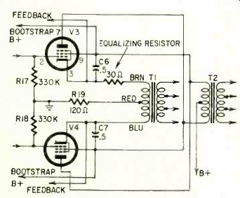
Fig. 1-A variation that equalize cathode circuit resistance in the output
tubes.
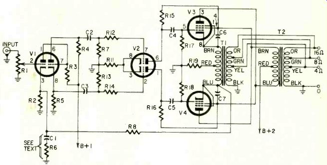
Fig. 2-Basic circuit of a more powerful twin-coupled amplifier.
To go about the design, first decide what output tubes (V3, V4) you want to use and the operating conditions.
If you want to go to more than 20 watts, you should use the larger transformer
- Chicago Standard A-8098.
It has balanced primary halves, more handling capacity and better mixing for high-frequency response. Its primary impedance is 2,000 ohms center-tapped, intended for use with tubes having a normal plate-to-plate load requirement of 4,000 ohms.
With slight variations, almost any output tubes can be used, with the suitable output transformer. To show how to figure circuit values, we will take EL34's as an example. The Mullard tube manual lists a condition using 375 volts B-plus with cathode bias, to give 35 watts output. The plate-to-plate load is given as 3,500 ohms for this condition. With a 4,000-ohm plate-to-plate load (using two A-8098 output transformers), these tubes should give better than 30 watts, assuming we get the same voltage swing with the higher load value.
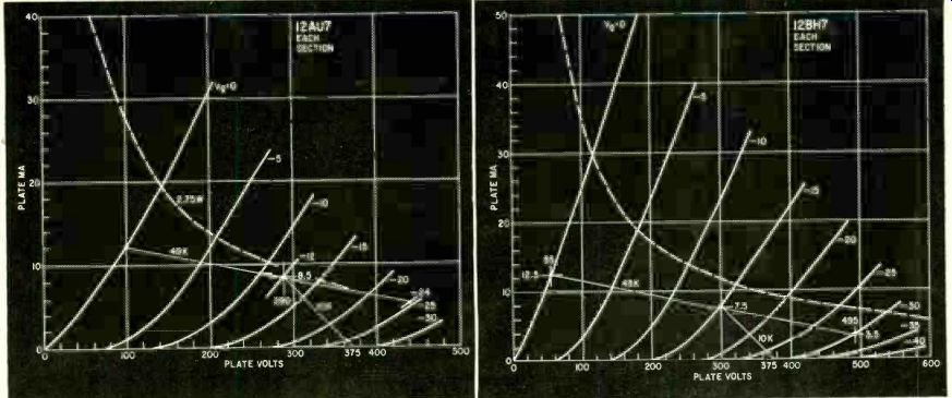
Fig. 3--Construction showing operation of a 12AU7 as a driver.
Fig. 4--A gives plenty of swing
Swing does not have sufficient margin. as a driver.
To deduce the available output voltage swing in the plate circuit, from which we work out all the other swings, use the condition indicated in the Mullard tube manual tables: 35 watts output with a 3,500-ohm plate-to-plate load. This works out to 350 volts rms, using the formula V = V WR. We are interested in swing. Peak voltage will be 500, and peak-to-peak, which is swing, will be 1,000. Of this, 500 volts will appear across each primary, and 250 volts across each half primary.
Don't forget, while we figure out operation in terms of swing or peak-to-peak, a meter measures rms (on a sine-wave test signal). So when you check operation, divide the swing value by 2.83 to get the reading you should expect on an audio voltmeter.
To get the output swing we have just figured, the tube manual says the grids need an input of 40 volts rms, grid to grid. This will be 20 volts rms per grid, or 56 volts swing per grid. But this 56-volt swing is required from grid to cathode, and the cathode swings 250 volts because of the output voltage.
So each driver stage has to deliver 250 + 56 = 306 volts swing to its output tube grid.
The driver stage Now we look for a driver stage. First let's try a 12AU7. The only way is by drawing the load line on the curves.
First we put in the maximum voltage and dissipation (Fig. 3). If we use 10,000-ohm resistors in the plates (R15 and R16) and about 12 volts bias, the operating point is about 290 volts, 8.5 ma (from the 375-volt supply). For a 56-volt swing, measured grid to cathode of the output stage, the grid swings 306 volts. So this 10,000-ohm resistor has only 56 volts (audio) across it, although the plate is delivering 306 volts audio. This means the effective value of the 10,000-ohm resistor for plate coupling, in the 306 dynamic sense, is multiplied by 50 or about 5.5, which makes it look like 55,000 ohms.
The grid resistors (R17, R18), which should not be higher than 470,000 ohms to satisfy operating requirements of the output tubes, do not get multiplied in this way because they have to be returned to ground. So the effective ac plate load is 55,000 ohms in parallel with 470,000 ohms, or about 49,000 ohms.
Laying a 49,000-ohm load line through the operating point. and estimating a 24-volt swing (twice the bias voltage), plate swing is from 100 to 440, or 340 volts. To use this dynamic operating point, one tube passes 12 ma (at 100 volts) while the other passes 5 ma (at 440 volts). The total current is 17 ma on dynamic swing, or 18 ma in quiescent condition, and we require 12 volts bias. So the cathode resistor (unbypassed) must be 680 ohms.
This is just enough, but it allows too little margin for comfort. To be sure of getting enough swing, let's try a 12BH7-A (Fig. 4). Again using a 10,000-ohm plate resistor (R15, R16), this time with 15 volts dynamic bias, we get an operating point of 300 volts, 7.5 ma, which is within the rating of the tube.
With the same 49,000-ohm dynamic plate load, the swing is now from 55 volts, 12.5 ma to 495 volts, 3.5 ma. The voltage swing is much more adequate: 495-55 = 440 volts. The cathode resistor (R11) needs to give 15 volts bias with a total current of 12.5 + 3.5 = 16 ma. Probably 1,000 ohms is close enough, in view of the reserve.
This will give close to the same quiescent operating point, because each tube passes 7.5 ma with 15 volts bias.
For the EL34 bias, the Mullard tube manual lists 260 ohms per tube. Each half primary of the A-8098 transformer measures 55 ohms, so an additional 205 ohms per tube is needed.
For two tubes, this value is halved. A 100-ohm resistor (R19) is close enough.
Total maximum signal plate and screen current is 227 ma (2 x 94 + 2 X 19.5), which will give a 22.7-volt drop and dissipate 22.7 x 0.227 = 5.15 watts.
A 10-watt resistor should be used.
The driver plate resistors (R15 and R16) drop 75 volts with 7.5 ma, a dissipation of a little more than 1 watt, so at least 1-watt resistors should be used here. A 1-watt resistor is plenty for the driver bias (R11) and other resistors in these stages.
-----------------
PRINTED CIRCUIT AVAILABLE RADIO-ELECTRONICS is pleased to announce that the printed-circuit board used in the Twin-Coupled Amplifier can be purchased by the constructor. By special arrangement, you can get a Twin-Coupled Amplifier circuit board for $2, postpaid, from RADIO-ELECTRONICS, 154 W. 14 St., New York II, N.Y., or Electro Technik Co., 19456 Meyers Rd., Detroit 35, Mich. Both sides of the board you will receive are shown in Fig. 9 of this article. In future issues, printed-circuit boards for other construction projects will also be made available.
--------------------
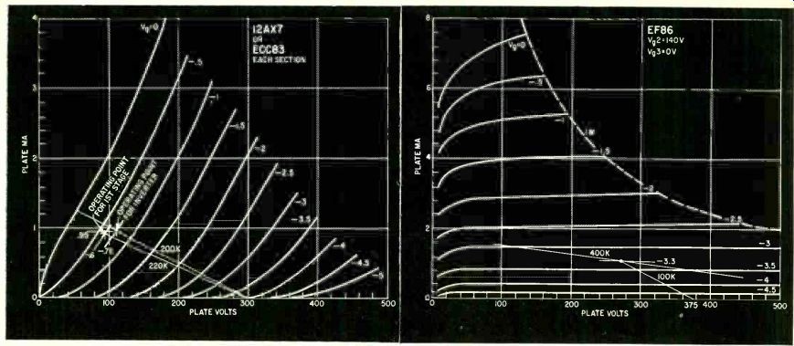
Fig. 5--Finding values for circuit in Fig. 2 using a 12AX7 or ECC83 voltage
amplifier and phase inverter.
PLATE VOLTS
Fig. 7--Characteristics of an EF86 showing operation as a bootstrapped driver with a gain of about 500.
Phase splitter and voltage amplifier
The driver stage will need 30 volts swing on each grid (twice the bias voltage). This a 12AX7 will do easily with either circuit (Fig. 5). Using the arrangement of Fig. 2, with 100,000 ohms in both cathode and plate of the phase-splitter section (R4, R5), the load line is 200,000 ohms. Supplying 300 volts B-plus to this point, the minimum tube drop is about 60 volts. With the dynamic load line, due to paralleling the following-stage grid resistors (R7, R13), the minimum tube drop is somewhat greater, so allow 75 volts. This will be the minimum bottom swing from the operating point, with 15 volts in each load, plate and cathode. So the tube operating voltage should be 105. Make it 110 volts to give a slight margin. This leaves a 190-volt drop to the dc load resistor, 95 volts in the cathode and 95 in the plate.
Now the other half of the tube has to provide a direct-coupled grid voltage of 95 positive ( strictly this should be less the bias of the second stage, which would make it 94.3 volts). Using a 220,000-ohm plate resistor (R3), this needs a bias of 0.6 volt with 0.9-ma plate current. So the input stage bias resistor (R2) must be about 680 ohms.
This is also the bottom leg of the feedback network.
The phase splitter and voltage amplifier operate from a 300-volt source (B-I1) so a series resistor is needed to reduce the available voltage (B+ 2)
to this level. A 39,000-ohm 1/4-watt resistor passing 1.85 ma will develop the required 75-volt drop.
The stage has a gain of about 70, so the 30-volt output swing needed for the phase-inverter input (the phase-inverter gain is very nearly unity from input to each output) is obtained with about 0.43 volt input. If we use 14 db of feedback, the input has to be about 5 times this, or 2.15 volts swing, which is 0.76 volt rms. To get this feedback, the voltage across R2 has to be about 4 x 0.43, or 1.72 volts swing. The swing on V4's cathode, from which this is derived, is 250 volts. So resistor R8 must be 680 X i 72-100,000. Coupling capacitor values follow the original circuit. Also R12, R14 and R13 (with R7 made the same-270,000 ohms). If a 400-0-400-volt power transformer is used, total current is 227 ma for output tubes, 15 ma for the driver stage and almost 2 ma for the input stages: a total of 244 ma. A 5U4 with capacitor input filter will take care of power requirements. Using a 10-µf input capacitor, the output voltage is about 470. So the smoothing resistor must drop about 95 volts at 244 ma, requiring 370 ohms at 23 watts. A 350-ohm 25-watt resistor will serve. C8 must be rated at 500 volts.
Those are the calculations. But after building the amplifier, check the operating voltages, both quiescent and with power. The plate voltage of the 12BH7 should be 300 (assuming the B supply ends of R15 and R16 get 375 volts). The cathode and plate of the second half of the 12AX7 should be 95 and 205 volts, respectively (again assuming the supply point is 300 volts). If not, the bias resistors (R11 or R2) need changing to get the voltages right.
Don't forget, if you change R2, R8 needs changing in the same ratio to maintain correct feedback.
Network C1-R6, from V-la's cathode to ground, levels off the response to around 20 khz when working into an open circuit or a resistive load. If the speaker system includes an electrostatic tweeter, this R-C network produces a 6- to 8-db boost at around 20 khz. This boost can be minimized by eliminating C1 and R6 when using an electrostatic tweeter.
If you use the original first-stage circuit (See RADIO-ELECTRONICS, June, 1960, for full schematic, or November, 1957, for original article), adjust R9 and R10 with signal passing and feedback connected, until signal voltage on both driver grids is equal. This is more easily done experimentally than by calculation.
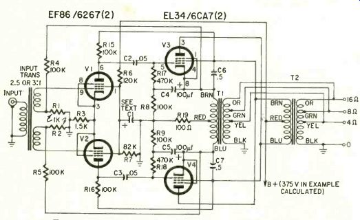
Fig. 6--Circuit using bootstrapped pentodes for drivers.
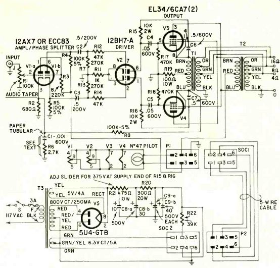
Fig. 8--Schematic of the complete 35-watt twin-coupled.
B-plus voltage is adjusted by varying R21's slider.
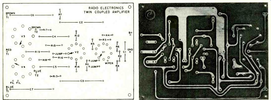
Fig. 9--Top and bottom views of the printed circuit board. Drawing and
photo are almost exactly half size. Board used measures 7 1/4 x 5 1/4 inches.
If you make your own, add about 1/8 inch along each side to simplify mounting.
Drill an additional mounting hole in the center of each long side to reduce
flexing.
-------------
R1--pot, 100,000 ohms, audio taper
R2--680 ohms
R3--220,000 ohms
R4, 5, 8--100,000 ohms, 5%
R6--2,700 ohms
R7, 13270,000 ohms
R9, 10--not used see text
R11--1,000 ohms
R12, R14 47,000 ohms
R15, 16 10,000 ohms, 2 watts R17, R18--470,000 ohms
R19-IC1 ohms, 10 watts
R20-300 ohms, 20 watts
R21-75 ohms 10 watts, adjustable
R22--39,000 ohms
All resistors 1/2-watt 10% unless noted
C1--.001 µf, 600 volts, paper tubular
C2, 3--0.5 uf, 200 volts, paper tubular
C4, 5--.05 µf, 600 volts, paper tubular
C6, 7--0.5 µf, 600 volts, paper tubular
C8--30, 10 µf, electrolytic, 500 volts minimum
C9--40, 40 µf, electrolytic, 500 volts minimum
F-fuse, 3 amps J-phono jack
SOC1 connector, female, 6 prongs, cable type
SOC2 connector, female, 6 prongs, chassis type
P1 connector, male, 6 prongs, chassis type
P2 connector, male, 6 prongs, cable type S-spst
T1, 2--output transformers: see text
T3-power transformer: primary 117 volts; secondaries 800 volts, ct, 250 ma; 5 volts, 4 amp; 6.3 volts, 5 amp (Stancor PC8413 or equivalent)
V1--12AX7 or ECC83
V2--12BH7-A
V3, 4--EL34 /6CA7
V5--5U4-GTB
Chassis-see text
Sockets, (2) 9-pin shielded top-mounting type for printed circuits
Sockets, (2) top-mounting octal type for printed circuits
Fuse extractor post
Barrier strip, 4 terminals
Tie strips (3), lug-type; 3 terminals
Grommets, miscellaneous hardware
------------------
Transformer input
Another variation requested was a surprise to me-a circuit to use transformer input. To do this effectively, much more gain is needed from the driver stage, so two stages (drive and output) are sufficient. This is done by using a pentode driver and taking the bootstrap feedback a little further, to include the output stage grid resistors.
Fig. 6 shows the circuit.
The output stage is the same as the one we have just worked through and requires a 306-volt swing per grid, of which 250 volts appears at the cathode.
The driver uses two pentodes, which can be EF86's. Using a 100,000-ohm plate resistor (R15, R16), coupled to a 470,000-ohm following grid resistor (R17, R18), and 3.3 volts bias, the gain is approximately 500 (using a dynamic load line of 5.5 x 80,000, or 440,000 ohms (Fig. 7). This means the grid input swing for 306 the EF86's must be about 500-0.6 volt. Inserting 2.4 volts (4 X 0.6) in the return of the input transformer's grid windings gives 14-db feedback.
The input swing per grid winding must be 3 volts, or about 1.06 volts rms.
One of the stock line /plate to push-pull grid transformers, with a stepup ratio of 2.5 or 3 overall, will permit driving this amplifier from a cathode follower output delivering 1 volt rms.
The feedback resistors can be 1,000 ohms (R1, R2) and 100,000 ohms (R4, R5), to provide the 100-to-1 reduction from 250 volts to 2.4 (approximate). The only remaining details are the bias and screen voltage arrangements and the output-stage grid decoupling, to permit bootstrapping the grid resistors.
The EF86's need 3.3 volts bias with a total plate current of 2 ma, plus about one-sixth of this as screen current. A 1,500-ohm resistor should be right for this. Screen voltage must be 140, to use the operating point the curves were based on. Estimating screen current (two tubes) as 0.3 ma (one-sixth plate current) and swamping it five times with the potentiometer feed, the top part (R6) has to drop 375-140 = 235 volts with 1.8 ma, requiring a resistance of 130,000 ohms. The bottom part (R7) needs to drop 140 volts with 1.5 ma, requiring 93,000 ohms. Preferred values of 120,000 and either 91,000 or 82,000 ohms should serve.
A large capacitor (C1) is needed to decouple the screen because of the high stage gain, which means the screen will be susceptible to the amplification of any hum voltage fed to it. Try a 100-µf 150-volt electrolytic.
The output-stage grid decoupling requires full cathode swing voltage to be coupled to the bottom end of the grid resistors. There is a dc voltage across the capacitors used for this ( C4, C5) equal to the bias of the output stage (22.7 volts) . So a 50-volt electrolytic can be used, say 100 µf. The resistors (R8, R9) absorb a small portion of the output power (as do feedback resistors R4 and R5, which at each cathode "see" a 1,000-ohm load resistance (one-fourth the total plate to plate). Making them 100,000 ohms means that only 1% of the proportion of power coupled by the cathodes will be fed to these resistors. The total grid circuit resistance is now about 600,000 ohms (470,000 + 100,000). In setting this circuit up, as with the others, check all dc voltages and then see that the signal voltages are also what they should be.
A practical circuit Following the design procedures outlined in this article, the staff of RADIO-ELECTRONICS developed the 35-watt twin-coupled amplifier shown in Fig. 8 and the photographs. The amplifier was constructed as a two-chassis unit with printed circuit wiring in the audio section.
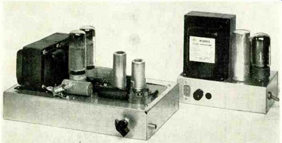
----------Top of the twin-coupled amplifier. Printed-circuit board makes all parts readily accessible.
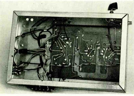
-----------Under chassis view of the 35-watt twin coupled amplifier.
The sockets for V1, V2, V3 and V4 must be oriented carefully before mounting. Mount sockets for V3 and V4 so the arrows on the mounting fall be tween pins 1 and 8. Mount V1 and V2 sockets so the arrows point to the space between pins 1 and 9. The arrows on the V1 and V2 mounting locations point to extra holes used for ground leads for the tube shields.
The prototype audio section of the amplifier was built on a 7 x 11 x 2-inch chassis. But, since B-plus voltage appears on some points on the top of the printed circuit board, we recommend that you build this section on an amplifier foundation kit (a chassis with a matching ventilated cover) such as the Bud CA-1751 or ICA 3966.
The power supply, connected to the audio chassis through a five-wire cable, fits nicely on a 5 x 7 x 2-inch chassis. Input filter resistor R21 has its adjustable slider connected to the positive end of C8-a. The slider is adjusted for 375 volts at the B-plus ends of R15 and R16 (blue and brown leads of T2).
= = =
Also see: New Phono Stereo PICKUPS
International Dictionary of Applied Mathematics (ad)
Radio-Electronics-- (USA print magazine)