By JOHN PORTER
Here's a one-chip test-gear project that's worth its weight in Hertz’s!
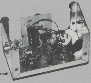
----------- COVER-OFF VIEW OF THE MINI AUDIO GENERATOR reveals a miniature
circuit board which mounts the IC and several other small circuit parts.
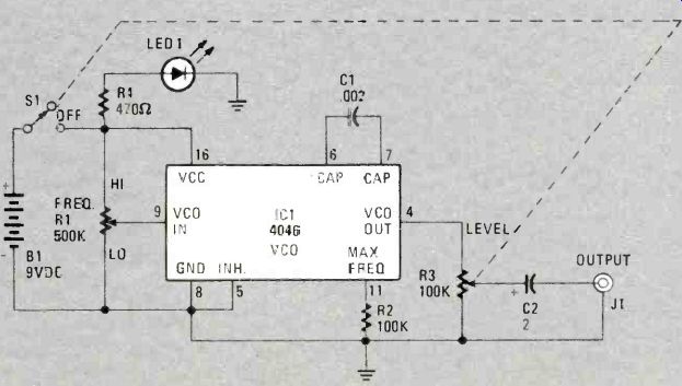
FIG. 1 PHASED-LOCKED LOOP CHIP 4046 is the heart of the Mini Audio Generator.
However, only the voltage-controlled oscillator (VCO) section is used. Enough soup comes out of the chip to power a small loudspeaker, although the intent of the circuit design is to provide a signal for injection to a circuit under test.
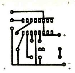
FIG 2. FOIL-SIDE VIEW of the printed-circuit board copper foil.
This illustration can be used as a pattern to making yours. If you wish, use pre-etched standard-layout boards to construct the circuit and save the etching mess. Otherwise, you may consider wire-wrapping the circuit.
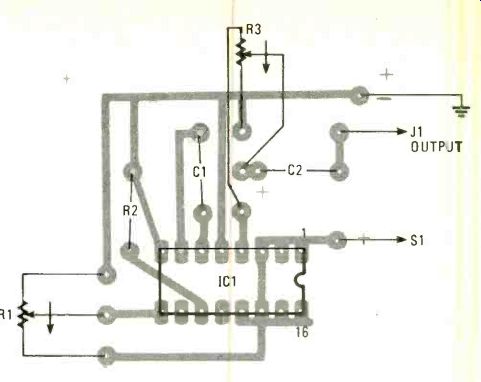
FIG 3. HERE'S AN X-RAY VIEW of the printed- circuit board with the parts
mounted on the "flop" side of the foil surface. Nothing is too
critical, so that the novice could "re-layout" the design successfully
to suit his own requirements.
---------------
PARTS LIST FOR MINI AUDIO GENERATOR
B1--9-VDC transistor battery
C1--0.002-u.F, 25-WVDC ceramic capacitor
C2--2-uF, 15-WVDC electrolytic capacitor
IC1-4046 phased-locked loop integrated circuit
J1--RCA phono jack LED1-light emitting diode, red diffused lens
R1--500,000-ohm to 1-Megohm potentiometer
R2--100,000-ohm, 1/2-watt resistor
R3--100,000-ohm potentiometer with SPST switch (see S1 below)
R4--470-ohm, 1/2-watt resistor
S1--SPST switch mounted on shaft of R3; optional toggle-switch replacement may be used.
Printed-circuit material to fabricate 1 1/2 x 2-in. printed-circuit board, 9-VDC transistor-battery connector, 4 X 2 1/4 x 2 1/4-in. aluminum chassis box, 16-pin DIP socket, knobs, hardware, wire, solder, etc.
----------------
BUILT FOR USE IN TROUBLE-SHOOTING AUDIO SYSTEMS, THE simplicity and low cost of the Min Audio Generator should make it-of interest to anyone involved in servicing audio and radio equipment. Built around a single inexpensive integrated chip, this little generator will provide many of the functions found on instruments costing 20 times as much.
Contained in a 2 1/2 X 2 1/2 x 4 = inch aluminum chassis box, the generator is capable of putting out a signal ranging from 2 Hz to 18 Khz at a strength of up to 10 volts peak-to-peak. It will easily drive a speaker directly, making it ideal for signal-injection testing.
The circuit
Utilizing only the VCO section of the 4046 chip, the output frequency is controlled by the amount of voltage fed to pin 9, that being controlled by B1. (See Fig. 1)
C1 and R2 determine the operating frequency range of the VCO. Potentiometer R3 acts as a voltage divider to control the amount of signal available at output jack J1.
The squarewave output will be rounded off at the leading edge somewhat at the higher frequencies. The strong output is partly due to C2, which charges up on one half of the cycle, only to discharge on the second half. adding its charge to the pulse coming from the I.C. That makes it possible to obtain a 10-volt peak-to-peak signal although the generator is only powered by a 9-volt battery. (Of course, that amount of signal is only available with very light loading.)
The 4046 was chosen because it doesn't require a dual-voltage power supply, nor does it need a regulated supply. Also, CMOS chips draw less power than TTL chips, contributing to battery life.
The reason why R1 is not calibrated in the Mini Audio Generator is that output frequency varies as the battery ages.
That could be eliminated by adding a 7.5-volt DC regulator (a Zener-type circuit), but when originally designed the plan was to try for the least amount of parts within the circuit.
Building it
The Mini Audio Generator, if built exactly as shown, should cost less than $10.00, including the etchant for making the printed-circuit board. Fig. 2 is a same-size foil pattern used on the author's printed-circuit board. The circuit is so simple you may choose point-to-point wiring using the wire-wrap technique. There's nothing wrong with that idea! Fig. 3 shows the printed-circuit board with an X-ray view of the foil surface and the parts mounted on the board. Placement of parts is not critical so you may design your own printed-circuit board.
Since the 4046 is a CMOS chip, the proper handling precautions relating to static electricity should be observed.
Furnishing such a healthy signal requires a fairly large supply of current (at least by CMOS standards) so LED1 is used as a power-on indicator, and reminds you to turn the Mini Audio Generator off when you are not using it, so as to conserve the battery. For best circuit results alkaline batteries are recommended.
Parts values are not at all critical, and close substitutions are permissible.
The Mini Audio Generator is a tough and versatile circuit. The author has used the generator and stored it in his traveling toolbox for more than a year, during which time it performed as required.
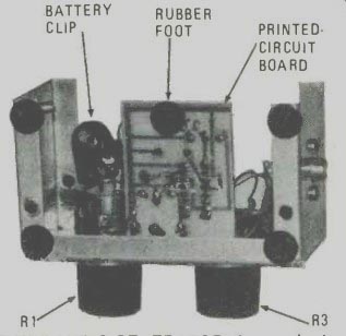
-------- INSIDE THE MINI AUDIO GENERATOR shows plenty of room for the
positioning of circuit parts. No problem here squeezing in all the parts.
Note that rubber foot on printed-circuit board was added so as to eliminate
the possibility of board touching the side of the chassis-box cover and shorting
the circuit.
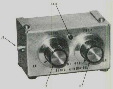
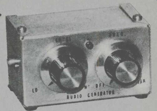
------- ITS WHAT'S UP FRONT THAT COUNTS when you are ready to operate
the Mini Audio Generator as a test device. LED1 is a power-on device serving
to prevent accidental battery drain.
Adapted from: Radio-Electronics--Special Projects (Summer 1983, #7)
= = = =
Radio-Electronics--Special Projects (USA print magazine)
Also see: Link | --Meg-O-Dapter